importing a dxf to the outline layer Board of Ultiboard
I try to import an outline of the map of another CAD file, but I have several problems. First of all, with the layer "Outline of the map" selected, if I import the .dxf file it place in white color, while this layer must be yellow. How to convince Ultiboard is the outline of the map?
My outline of the map also has a semicircular path in its perimeter; the entire Board is rectangular, but there is an outline of a semicircle on the side. When I import the .dxf, it comes out as a full circle. So no idea what is the problem?
Thank you
Hi Jweaver,
When you import an outline of the map, Ultiboard to import the settings of the DXF file, including the color layer. Often, this color is white in AutoCAD, and so when you import the file, the layer of the Board outline is white. You can check in the Toolbox of design and also change color to yellow.
Import DXF in Ultiboard has some limitations, which is probably why import is to convert the semicircle to a full circle. The next version of Ultiboard has some difficulties to import DXF, and unfortunately, there is nothing you can do until then. However, I encourage you to post the file DXF here so I can see if the problem is resolved.
Tags: NI Software
Similar Questions
-
Import data 'ESSBASE' in the physical layer, it is about the relationship.
Hi Experts,
In 11.1.1.6.0 administrative tools.
When import "ESSBASE" Mutiple resource data in the physical layer and change the type of inner join to a left join in the meantime Dim and made the sale in MDB, it doesn't in the response.
Are you facing th same question before? Thank you.Hello
have you checked "LEFT_OUTER_JOIN_SUPPORTED" of the physical layer - > properties - the database > features? by default, people with reduced mobility.
Thank you
-
Could not import a custom in the physical layer table
Background
**********
We are implementing the OBI Applications
The RPD is OBI (analytical) applications, a. We created custom tables and are now building the logic layer.
Problem
*******
Created a new custom table in the physical OBAW using the username of the OBI (analytical objects owner)
Connected to the BI-Admin offline using the user/pwd administrator name
Utility of used import, the appropriate custom table table (you can see in the dialog box), taken from the warehouse. It brings up the dialog box, and it looks like it is to import the table (by displaying the file flying over).
Updating of the RPD. Even tried to connect and again.
When you check the physical layer you do not see the custom table. Y at - it a cache that needs to be eliminated?have you checked if it creates a new connection pool and the table under this new connection pool?
-
How can I separate the images on a vehicle imported, it has linked the layers Layer
Can you please tell me how to separate the elements in this image of an any vector graphic stock?
I can't ungroup and the layer said linked layer, how to isolate the parts of Scripture and replace it.
I have several vectors in .eps downloaded and none of them come apart. Thank you

It is the vector. I did not notice that he was bound.
Click on the drawing. Choose the Selection tool (black needle, you have the map tool selected in the screenshot).
Select it by clicking it once. On the context menu bar you should see the embed button.

You can then access bazzillion of drawing parts.

-
How to import excel as sorce of data file in the physical layer OBISE correctly?
Hello world
I am trying to import an excel as a data source in the physical layer OBISE. I create the ODBC which link to the correct file (http://www.oracle.com/technology/obe/obe_bi/bi_ee_1013/bi_admin/biadmin.html#t1)
only imported the Excel using the import of database tool in the administration of Oracle's BI. I see the Excel but I can't see data in it. Can you help me, please? I'm new in the present.Do you have a range in excel file?
The name of table range represents in the physical layer after you import excel file.
See this example of blog:
http://obiee101.blogspot.com/2008/06/OBIEE-Excel-import-prepping-data.htmlHave you used the import of database and select excel data source that you created in ODBC?
I did the same thing and works for me.
Save first repository and display the data and verify the source of data/name connection pool in your excel database directory.
Concerning
Goran
http://108obiee.blogspot.com -
Add physical column in advance in the physical layer without using import
Hi Experts,
Is it possible to add new physical column in the physical layer in advance if you already knew that this new physical column is added to the OLAP table in the future?
Thank youHello
Yes you can do it. Make sure you use the same column in the report once you add the column to the OLAP table.check if useful/correct...
Thank you
prassu -
Problem in import of DXF files in version education Ultiboard 11.0
Hey guys,.
Use Ultiboard 11.0, the education version. Trying to import a DXF file designed in solidworks for my PCB. The DXF file
also one through a molex connector that has already drawn in solidworks and actually fits. The problem is,
How can I create a real fingerprint THT this connector using the holes that are already in the Board outline. Also wonder what
the problem might be because when I import the file as a contour of the card then in the mode of the print edition, the sketch does not need to be
chosen or even modified. What is a limitation of the circuit design suite education edition?
Hello
First take a quick lok at this, it's a KB on the import of dxf files.
http://www.NI.com/white-paper/13722/en
If it's all for you so, can I get more details about this issue? The DXF files and your work ultiboard would be ideal to start to see what I can do to help you. There are many things that you need to support importing DXF files (take layered account, connections, etc.) and sometimes it raises problems of compatibility, but there is no limit with the educational version about the import/export of dxf files.
Kind regards
-
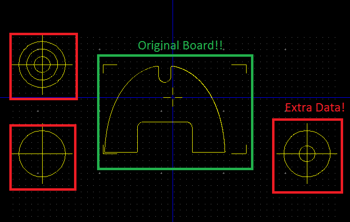
I see additional data when I export the outline of the map of my design as a file gerber
Hello
Whenever I have export files gerber my project and use any viewer Gerber to check my design that I encounter the following error. In the outline of the map layer, and more the contour of the actual card, one would expect to see, I see three additional points around the Board. These circular marks seem to have added around my board every time I do an export using Ultiboards built on the basis of export. I enclose a snapshot of the look of my layer of the Board outline and you can clearly see the three circular spots around my Board of Directors. I also enclose my main project for your comment file. Any help will be appreciated.
Thank you
RD
Hello
What are the alignment markers.
If you don't want them, turn them off:
go to the OPTION menu
the global preferences
On the PCB Design tab, you will see a box with the post-processing
Here, you can turn off snap lines
success!
-
effect of contour of the shape layer
Hi, I'm applying an edge effect to a layer I imported from Illustrator.
I created vector layer with the layer (so it appears as "outlines") and can apply STROKE if I go to 'Add' in the timeline, but not if I apply via 'generate' it does not appear and also impossible to apply effects. I can change the specifications, the width of the line IE, but nothing appears on the screen.
Kind regards
Suzie
Doodle works and stroke on the footsteps of mask, not on the shape layer paths. If you want just for just these types of effects mask path, so you don't have to use "Create forms of vector layer" and instead of this just leave the layer being and copy - paste the path like I showed you before. Another way to do it, if you have already converted to shape and stay in shape too, is to copy the path of the path parameter of shape for the mask path setting (you can simply create a dummy mask so you where to copy)

BTW shape layers have also a few very powerful path here operations: wiggle path can create the very nice and organic Scribble to your contours. but it is not the same as the Freehand drawing.

-
Draw the outline of the particles found by ParticleReport
I use Vision Module 2009 for .NET and c#
My question is how can I draw the outline of a particle found by the ParticleReport(). I tried GetPointsOnContour() but it does not offer the full outline.
In addition, I want to use this particle as a KING for any use.
Thanks for your help.
The same problem is discussed here for LabVIEW:
http://forums.NI.com/NI/board/message?board.ID=200&message.ID=14826#M14826
However, you are using. Fortunately, the same concepts will still apply. Instead of the LabVIEW VI "IMAQ MaskToROI", you must use the MaskToRegions method.
Kevin C.
National Instruments -
Create the outline of a complex shape
Here is a picture that I got online... it has a very complex shape

Put this image on a layer, how a schema is possible outside curves, so that only the outline, that is, the exact shape of the object, appears as a single line on the layer? The magnetic Lasso tool is not usable on such a complex form.
Then I could change the contour using blending Options, change of color, etc..
CS2 running
Method 1:
-
The presentation layer object permissions question
Hi Experts,
We had a product supplied by Oracle. The presentation layer objects have read access to the user authenticated. Now, we have created more than a few tables and imported into the presentation layer. So by default, objects are having no access. We would like to change the permissions of access forbidden to read. How can we do it for all the objects at the time? We are not able to see in the roles or users to identity the authenticated user. In the level column, we have this issue.
Ask the experts to help understand me this about this user and where do I set the permissions correctly.
Thanks to the Adv.
Hello
Change of access authorization shall read:
Step 1: Resume of RPD
Step 2: Copy the subject - (area some object you want to change the permissions)
Step 3: Paste the topic for notebook
Step 4: Replace the text 'no access 'to' read '.
Step 5: In step 2 you had previously copied by any sector of activity, just remove the subject box in the presentation layer of RPD
Step 6: Copy the text from Notepad and paste into the presentation layer of RPD
Step 7: Save the PRD
-
How to create the outline of the shape
How to create the outline of a shape, solid, dashed, or dotted, for example an empty rectangle or circle.
Something like these:

I need are blank lines, empty interiors, which is transparent.
Thank you
If you use CS2, you can use the layer style > stroke and adjust the opacity of fill to 0. It would be more difficult to make a dotted line. Most likely, you will need to create a mask for this.
-
Hello experts.
I've download a RPD on my local machine. I have already imported all of the tables used in this RPD on my local machine. I created the DSN (obiee_reports), and the test connection is successful.
I created a pool of connections with the DSN (obiee_reports). However, when I try to "view data" in the physical layer, the system throws an error "connection failed". Also, I am unable to create any analysis.
I m do not know what I missed. Please notify.
Thank you and best regards,
Serene
If you use Oracle db then go to OIC as calling interface.
HostName: port / ServiceName would be one that is suitable for use
-
HI - can help I'm going crazy! !
I drew a shape with the tool pen (which took me Age..) and I go back an image that I imported, I cannot select once again it. I can see it in red, but I'm not able to select once again it. I have the selected layer, but there is no sign of it in my Panel of traces at all. I tried clicking on the direct Selection tool (about 100 times), I tried the Brush tool. I've tried everything. The same thing happened to me the other day... Please can someone help! Tania
It's the plug technique on the subject:
Using Photoshop | Manage paths
It contains this point under manage paths:
When using a shape or pen tool to create a work path, the new path appears as the work path in the tracks Panel. The work path is temporary; You must save it to avoid losing its contents.
OK, the red, you mentioned is a Stoke you added. Then quick mask is not involved.


Maybe you are looking for
-
iOS App Store still shows apps to update
Even AFTER I downloaded and installed applications, the app from the App Store continues to show 32 apps must be updated on the Red badge. I restarted my iPhone, but that did not help. Any suggestions?
-
Satellite L500-13D - Bluetooth turns on itself after turning off
In Vista preinstalled has worked. Since I installed Windows 7 and all Toshiba drivers, I have problem with bluetooth. When I disable it, it turns on automatically after a second or two. Today I installed the latest driver for Windows 7 bluetooth stac
-
Commander supreme 1 I lost my drive there at - it a patch or crack, that I could use so I don't have to buy the game again
-
LaserJet Pro M176n MFP: Region of LaserJet toner is locked
Hello I want to know if the HP LaserJet (specially for the M176n) toner cartridges are region locked. We hope power boat include these printers with the our company product, but they will go in many different areas, we must ensure that the local repl
-
I deleted this file system 32 but he continues to appear
Original title: shunimpl.dll will not disappear I deleted this file system 32 but he continues to appear. I searched on the file system and the registry. He's not here, but he continues to appear.