Draw the outline of the particles found by ParticleReport
I use Vision Module 2009 for .NET and c#
My question is how can I draw the outline of a particle found by the ParticleReport(). I tried GetPointsOnContour() but it does not offer the full outline.
In addition, I want to use this particle as a KING for any use.
Thanks for your help.
The same problem is discussed here for LabVIEW:
http://forums.NI.com/NI/board/message?board.ID=200&message.ID=14826#M14826
However, you are using. Fortunately, the same concepts will still apply. Instead of the LabVIEW VI "IMAQ MaskToROI", you must use the MaskToRegions method.
Kevin C.
National Instruments
Tags: NI Hardware
Similar Questions
-
Can I use Illustrator to draw the outline of a photograph and get an outline of art beautiful line of items in the photo? I tried to do this by using the Trace of the Image, but I can't select the paths that result and assign a stroke to path. How can I do this?
Please see the photo
-
Anyone know of a tutorial or an example to learn how to draw the 3D dice in Adobe Illustrator?
I actually found a link to a tutorial on how to do it, but don't know if the announcement of such a link is allowed in the forum. (I'm new here.) He quite far up to a certain time and then it becomes unclear how one of the steps, or I don't know enough yet about using Illustrator to understand what he says to do. In any case, I get so far and then I can not look polished. I understand the basics for creating a drawing in 3 dimensions, so don't looking for this.
OK, I got quite a breakthrough!
I went ahead and have materialized to where I got the same result as above, where only the side '6' watch points, while the other two are blue.
But then I was playing with the outline, making visible/invisible parts. That's when I noticed, there was the '4' and '5', but they were BEHIND the blue. Not before blue as I expected.
It's simple. Only, I selected the two blue faces and used object/rearrange/send backward to position behind the faces dotted.
After that, I was also able to select the blue edges and put a radiant on them. It is not yet exactly as this step in the tutorial, not until I find how the gradient tool. But I'm certainly happen.
At this point, it looks like:

And that is a SIGNIFICANT improvement on what I had before, if I say so myself. At this point, I'm probably on my way to following through with the tutorial, I started from.
-
Draw the shape of shortcut Center (option) does not (eyedropper instead)
Hello!
I have a little problem with the tool shape in Photoshop CS6 (Mac). I have not noticed when it started, but before, when I wanted to draw a shape from its Center, I would hold the Option key, key, but now when I do, it appears the eyedropper tool. The shift key still works to draw perfect circles or squares.
I looked in preferences but haven't found anything related to that. Of course, I could click on the gear icon on the top bar and check the center of From option, but who would defy the general idea that underlies the keyboard shortcuts...
Thanks for the help!
What happens if you start to draw the shape, then press and hold the Alt key? The same thing happens?
-
where can I find the chassis for the import file in MAX to draw the circuit diagram before you buy
where can I find the chassis for the import file in MAX to draw the circuit diagram before you buy
chassis: NI SMU-1078
ini file to import into MAX
See attachment
THX
Hi again Koen,
Unfortunately, you can't simulate a complete PXI system, so we do not have the ability to simulate a PXI controller unit. The simulation, you can do is to set up the cards you want to use in you.
concerning
Lars -
The best way to draw the difference of phase vs. time of two signals
I have three channels (time, force, displacement) of approximately 1 000 seconds of a sinusoidal test load test data (sampling rate was 100 Hz). I would draw the difference in phase between the force and displacement (perhaps using a second window 30) according to time. I tried using a few different analysis functions, but I get what looks like random noise (phase difference between force and displacement is very small and the difference in amplitude is very fantastic - 4 orders of magnitude). Any suggestion would be appreciated! -Jim
Hi Jim,.
The phase channel resulting, that you get with the function FFT DIAdem is in the frequency domain. If you select a channel data and time in the FFT dialog box, you will get a frequency channel that results as well as the Phase channel resulting. If you select only a weather channel of waveform data in the FFT dialog box, you will get a Phase of waveform frequency channel resulting.
Brad Turpin
Tiara Product Support Engineer
National Instruments
-
Draw the rectangle to the intensity chart (position where clicked)
I am able to extract the coordinates using the mouse down and mouse to the top of the structure of the event, but unable to draw the rectangle at the specified position. I get the coordinates to the mouse down and mouse up to the event within these limits. I want to draw a rectangle in the position coordinates, but unable to do so.
One last thing, since you use the Rectangle to draw, you need to deal with cases where the rectangle is not drawn from top left to bottom right. Please make sure that the minimum value X goes to the entrance on the LEFT and the minimum value of go at the TOP of the terminal of the vi entrance Rectangle rect. Use the Max & Min function from the palette of comparison for that.
Ben64
-
Is it possible to draw the same color for each curve automatically
Hello
Is it possible to draw the same color for each curve automatically. I use graphic XY basis with data set.
Lol you'll either need to set the properties through the dialog box. Or use the nodes property of the graph to adjust the Active plot and then set the color of the plot. This can be done in a loop For.

-
How to draw the lines automatically
In LabVIEW I must draw a line automatically (both vertically and horizontally) the user will define the vertical and horizontal number lines.
Is this possible with LabVIEW
 Thanks in advance
You move to the point of departure of the line using "move the pen", and then draw the line using "draw the line".
Repeat for each line. (using for example a for loop and autoindexing on positions).
-
Analysis of the particle pixel measurments - how to get the co - ADR of the first pixel
Hello
I'm developing some labview code to measure particles.
I'm having trouble with the analysis of the particle VI. I'm not sure what values of table, I need the table to return the co - ADR of the first pixel (more to the left the higher pixel) and also any useful information!
I joined the program, I worked on that. To test I'm loading a black bitmap with some white circles on it.
Thank you
Jack
Right click on the entry of measurement in pixels and select create constant. This will paste an empty array of metrics on your chart. Click on and select the first pixel X and the first pixel Y parameters, as shown below.

-
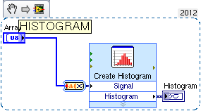
draw the histogram of the random generator of > > >
Hello
I have a bulit a random generator by using + 1 D Cellular Autómata LFSR
I need to draw the histogram of the system to check the shape of the distribution
I have the vision of labview
help me draw
I thank you in advace
concerning
Mathematics-> probability and statistics, below a histogram express vi that will help you.
-
Draw the last set of data (1000 samples) in a loop
Hi, I read a waveform data continuously, but I would capture and draw the last data set after my stop. As shown in the picture of attacehd, when the condition is true I acquire data. The number of samples per read is 1000, and as you can see I used a shift register to store data. What I'd like to see where the loop stops is the last 1000 samples but when I acquire real-time data I get a random sample number when the loop stops. sometimes 90 samples, sometimes 950 samples etc... could you please let me know how can I get the last 1000 samples acquired in this loop
I even used DAQmx buffer for data but I can not get the last 1000 samples
Thank you
If your task has a number of points to buy, I don't see how you could have a number UN predictable and random points in the buffer. The task should stop after having acquired the points of "N" and then say it's done.
What do you mean by "stop tripping? You only have a 'start' trigger and it is not available for points once the task has been involved. If you want the last 1000 points of the points "samples per channel", the last reading should return those. I've never used the property "Done" before. Count your samples read instead and stop once you have what you wanted.
-
This is the first time the following: failed: 1 update or the errors found Code 80070643. I followed through the Fix code he doctor. This morning the automatic update 4/16 showed failure: update for Microsoft Office PowerPoint 2007 (KB 24664594)
Hi William,.
First try the following article: http://support.microsoft.com/kb/971058.
If this does not work, try this link: http://support.microsoft.com/kb/923100.
While I'm not quite certain that the first will succeed, the second is a common and often recommended solution that has helped a lot with this error code.
I hope this helps.
Good luck!
-
How can I draw the intensity in real time of a picture in time real (imaq 1394)?
I have a firewire camera.
I hooked up my camera to my pc with labview and now I display image in real time. How can I draw the intensity of a region dependent on time?
Y - intensity
X - time... I would watch the variaions real-time intensity...Thanks in advance
The light meter example is pretty much what you want to do. It is located here:
\National Instruments\ \examples\Vision\2. Functions\Light Meter\Light meter Example.llb\Light meter Example.vi In the example, the x axis are the number of iteration, but it is easy to modify to use a graphic instead of a graph and chart the time instead.
Hope that helps.
Christophe
-
Display the full path of the files found in the search tool
I just moved my business to a new processor, and I can't figure out how to see the full path objects that I find using the search tool. It is not enough simply to see the name of the folder in.
Under Folder Options, I checked all the options available to display full path names, but all I get for a path name is [name of folder] results.
What Miss me?
How to display full path name?
The game, 29 July 2010 17:54:45 + 0000, rtorstrick wrote:
I just moved my business to a new processor,
"PROCESSOR"?
"CPU" means "Central processing unit". In modern furniture
computers, the CPU is a relatively small chip, one
integrated circuit. It is on the motherboard inside the computer
case. It is not the case itself, or the entire computer, which
includes the case and what it contains.I don't know how incorrect practice of the appeal of the entire computer
the 'CPU' has started, but here's my proposal: when you buy a computer, you
normally get the deal and what is in it, with a monitor,
keyboard, mouse and perhaps a printer. All of these devices
connect to the case. Because everything connects to the case, the case
are "Central" to everything, and the term "central unit".
has been misunderstood and misapplied it.and I can't figure out how to see the full path objects that I find using the search tool. It is not enough simply to see the name of the folder in.
Under Folder Options, I checked all the options available to display full path names, but all I get for a path name is [name of folder] results.
What Miss me?
How to display full path name?
Right-click on a file name, the research found and choose "Properties".
Ken Blake

Maybe you are looking for
-
I have to wait for the battery to be charged prior to the first installation of fullr?
-
My CD/DVD drive is not recognized. I go into the Device Manager and it says "Windows cannot start this hardware device because its information of configuration (in the registry) is incomplete or damaged. (Code 19) » I tried to uninstall then restart
-
Need to expand opening post page to e-mail the entire windows
Before I could open my email with a size full page when I clicked on the incoming mail. Now, he opens with a 3/4 page message. How to change that.I know that I can maximize every time, but who should not have to do.Also I got the page with the corn
-
Hi allWe are 11 GR 2 2 node RAC in win2008r2. I want to get report growth tablespace in good months for the last 6 months. I would be grateful if someone can help out me. The following query gives me a month only. I want month wise. Help, pleaseSELEC
-
HDD not getting detected on the host virtual esxi nested 5.5
Hi allon my home office, I installed ESXi on bare metal on USB. From a laptop computer, I was able to connect to it. I created an esxi embedded and followedHowto: create a nested laboratory However, it did not help.On the bare metal Office the esxi i