Instruments cluster interface
I'm doing my final year project on machine vision based instrument cluster of inspection, I have a good experience with LabVIEW and vision, but this project requires instrumentation running outside of a front vehicle vision real function of inspection to take place, how does take less part interfacing (move hands via USB SE)? should I go for the devices USB CAN go, OR I need to stimulate the cluster as possible what ever I can (speedometer, odometer, etc.), can someone guide me on this point, what the best strategy would be to go on the project?
Thank you
Nizamani,
Here is an article on the use of the virtual ports CAN.
http://digital.NI.com/public.nsf/allkb/ed9cf160dc07f09f862572c90072b13c?OpenDocument
You could write two loops which read and write through virtual ports of the CAN. In this way, you can replace the writings and readings with calls to write the material if necessary.
You can use the USB interface to send images to a physical device. So you could build a virtual instrument listen you while a parallel loop is send information to the virtual device built you.
Look in the window to find examples to find some simulated devices that may be useful for a starting point. You may be able to find another example posted in the forums or in the area of the developer.
Tags: NI Products
Similar Questions
-
Instrument ID query failed(ivi-com)
Hi all:
I tried to check the interchangeable function on ivi - com, so I used the fluke45 to replace the agilent34401, and the ivi - com driver is agilent.
I created a session driver for fluke45, he is respected in the agilent ivi - com driver.
But it works fine when I connect to 34401, it does not work when I am connected to the fluke45.
And when the code executed fluke45. Initialize ("GPIB0::22:INSTR", true, true, ""); have an error: Agilent34401: failed query tool ID.
I checked the gpib address and he's right, I don't know why it happened.
Can give you some ideas on this subject?
Thank you very much.Hello cat,.
There are specific IVI - C drivers for two of these instruments (ni.com/idnet) IDNet, I recommend using those since they are certified NOR and NOR-supported. If you want the interchangeability, you should call in the class of your IVI - COM instrument drivers interface or use class IVI - C drivers. Please answer the following questions:
1. what development environment do you use?
2. you use class IVI - C drivers?
3. What is the main purpose of your test application?
Thank you
NathanT
-
General questions about FPGA Interface C API 2.0
I developed an application in LabVIEW FPGA 2011 on a Board of the R-Series PXI and a host application LabVIEW 2011 Windows XP to communicate with him via DMA FIFO. I'm trying to adapt the interface to CVI 8.1 (preferred) or CVI 2009 using the Interface of FPGA C API 2.0. The example of FIFO that it stores in the directory C:\Documents and Settings\All Users\Documents\National Instruments\FPGA Interface C API\Examples\ gave me a few questions:
- The functions NiFpga_WriteFifoI16 and NiFpga_AcquireFifoWriteElementsI16 are two different ways to do the same thing? I wasn't clear where I do the extra copy if you use NiFpga_WriteFifoI16. I guess the combination of NiFpga_AcquireFifoWriteElementsI16 with NiFpga_ReleaseFifoElements is the way to go if I want to stay out of trouble.
- I intend to call NiFpga_Initialize and NiFpga_Open in an initialization function that gives the word initially, then keep the session handle in calls to other functions. The session handle is always not null when it opens successfully? Could I use it as a test to make sure that I have a session valid before calling any other functions-example:
If (session) {NiFpga_WriteFifoI16 (...)} - Interface of FPGA C API 2.0 is only announced work in CVI 2009 up on. If I include NiFpga.c and .h in my project CVI 8.1, it seems to compile fine, but I did have the chance to integrate yet. Is there something specific that would make CVI 8.1 not work? Our deployment environment of difficult application CVI upgrades
-Jim
Jim,
With regard to your questions:
1. Yes, these two functions are the same, however there is a big difference between the two. NiFpga_AcquireFifoWriteElementsI16 acquires, prepares and publishes FIFO elements to avoid the need to write the first in a buffer allocated by the separate user, then copy the contents of the elements in the memeory host buffer. Considering that, in the NiFpga_WriteFifoI16 does not work. So the NiFpga_ReleaseFifoElements should always be used with the NiFpga_WriteFifoI16. The example is just showing how the code should be used, but is not necessarily displayed works should be used together. I understand perfectly why he was confusing.
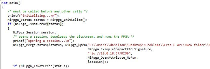
2. the best way to ensure you have a valid session is by using the NiFpga_IsNotError() function. I've attached a screenshot of the example code that illustrates how best to achieve this and inserted the image below.
3 regarding using CVI 8.1, there is nothing in particular, which would make your code does not work in point 8.1, but we can guarantee that C API 2.0 will work correctly with 9.0.
Kind regards
Larry H.
-
Automing instruments LabVIEW without using specific and coding drivers for each instrument?
Hello
I'm new to programming in labVIEW, but I had a few questions about its use in automation and remote controlling several instruments.
It is an ideal software for automation of various instruments remote control/test. Assuming that I have several different companies spectrum analyzers, I understand that labVIEW drivers of instruments or special VI who would control these instruments. But if I wanted that all these spectrum analyzers to say, to display on another computer using the remote control, but I wanted to use the same program for effeciency, is it possible to do so universally for all instruments using labVIEW? Or do I have to adapt this program for each instrument to instrument drivers cause?
If labVIEW can do that, is - anyone had good success for such scenarios in other programming languages?
Thanks in advance for your help.
Look for the Abstraction Layer material (that you can implement with LabVIEW, even if it's a slightly advanced topic).
The idea of having a specific Test and be able to enforce it against different Instruments, decided at run time, is the kind of situation that LabVIEW and use of HALs was designed to facilitate.
The concept is to 'Levels of Abstraction'. When you create a test, you can design it for an abstract Framistan, since all the Framistans are supposed to be able to measure Vorbels in the range of 0 to 100, so you just plug a generator of Vorbel to generate Vorbels in a certain sequence of Test (linear, random, quickly, slowly, pulsatile, continuous, you decide), measure your Abstract Framistan records readings and compare with the results you expect write the results in a nice report.
Of course, Framistat of OR uses Ethernet as the means of communication, while HP uses a serial port (depending on the model, series settings can change) and uses of the Intel one. DLL to communicate with the low-level API. So you also need to develop, for each specific instrument, an "interface" between its API and the Framistan abstract (not everyone uses Vorbels as the input unit, for example).
So the good news is that it can be done, the bad news is that one of the best ways of handling this type of question on the programming is to use OOP (OOP). A number of languages (LabVIEW, C++, JAVA) support OOP, but LabVIEW might have the advantage when it comes to interact with the material.
I you are looking for Hardware Abstraction Layer? Add LabVIEW to the search query and you should find some nice presentations by Elijah Kerry...
Bob Schor
-
Cluster SOA with BigIP as HTTPFrontEnd - deployed WSDL and XSD composite files are not accessible
Hello
In our SOA environment, we have an architecture like that.
We have a Cluster with two nodes of SOA. Each node is to have an OHS. There's a BIGIP which is the HTTP of SOA Cluster interface.
BIG IP load balancing and HTTP Port 80 and HTTPS 443 port.
All access to BIGIP is over HTTPS. With HTTP, we are not able to access the artifacts.
Here, we are faced with a problem.
All WSDL, XSD, deployed on the server files have as - ends http://bigiphost:80 / soainfra / .....
These end points are not accessible, and we have to manually convert URLS to https://bigiphost:443 / soainfra / ... for testing.
Main question is coming when we're trying to raise our composites to RJO. Because the WSDL and XSD files is seen port http endpoints and they are not accessible from the harvester tool. Where a failure.
Can you please how do ensure that all composite end point and endpoint WSDL are generated as Https://bigiphost:443 instead of HTTP Port.
I tried two options
(a) setting serverURL to https://bigiphost:443
This option modifies all the endpoints and the localities of XSD in a wsdl to the https address document. but it does not composite point endpoint and endpoint WSDL. They are still Http. so not accessible through harvester or browser.
(b) setting HttpsServerURL to https://bigiphost:443
It makes a difference.
Please suggest how can I convert a composite and endpoint WSDL (protocol header) end point to https://bigipport:443 instead of http:bigipport:80
Thank you
Jessyca
Finally got the fix.
Changed the HTTPServerURL property in the EM Console > SOA-INFRA > SOA Administration > common properties > more advanced properties
Https://bigipport:443the value HTTPServerURL.
This helped and all the endpoints and composite WSDL endpoints have been generated with https://bigipport:443 instead of http.
So overall, I used two properties.
(a) a HTTPServerURL - change the endpoint WSDL and the composite end.
(b) ServerURL - change endpoints in the wsdl file with the value set in the present.
Thank you
-
Satellite A300 - question about the MIDI connection
Can someone help me?
I have a computer laptop satellite A300 and want to connect it to my computer to stream TV and movies.
I don't see where I would plug MIDI to my computer.
Is it possible to do with this model?If not, can I get a plug that would stretch the capacity of the computer or I have to get a new computer?
Thank you
CarolSorry, but I m confused
You said you want to connect the Satellite A300 to a computer
Is this correct?You can connect two computers via a LAN cable. But I have no idea why you talking about connecting MIDI (Musical Instrument Digital Interface)
-
Hello
I can generate a C API interface for FPGA design in Labview Communications.
And how does it work?
Thank you
Sebastian
Hi Sebastian,.
If it is anywhere in the LabVIEW Communications, he'll be in tools Launcher. If it is not there then you can still generate a C API for your FPGA using the FPGA Interface C API generator. I received this the generating a C API for a help Application LabVIEW FPGA Document.
Generating a C API in the Windows Start Menu
Follow these steps to generate a C API for a bitfile compiled in the Windows Start menu.
- "" "" Select Start "all programs" National Instruments "FPGA Interface C API" FPGA Interface C API generator.
- On the Generator of API C FPGA Interface dialog box that appears, navigate to the compiled FPGA bitfile or type an absolute path for her.
- Select a directory for output to the C API. If you do not select an output directory, the files in the C API will be created in the directory that contains the bitfile. You can navigate to a directory or type an absolute path for her.
- Optionally, you can change the prefix for the generated files and constants in the generated .h file.
- If you are using LabWindows/CVI to develop your C application, check next to exclude NiFpga.h/NiFpga.cas FPGA Interface C API installs the header and library files with the support of LabWindows/CVI.
Make sure you have installed FPGA C Interface API .
Introduction to the API of C Interface of FPGA
See you soon
-
Hello
I installed Measurement studio 8.5 to work with my VB6. I can't find the led indicator. In what activeX should I find it? A I can't install something?
Thank you
Rafi
Hi Rafi2003,
The LED part of the user of National Instruments CW interface. When it comes to a selected component, you will see the CW (toggle switch) button in your Toolbox. You can put this control on your form and right click to bring up the properties. In the property pages box that appears, you will see the LED on the tab style of dialogue.
-
Rich project shared with IO Library?
I have an application that needs to share resources/instruments with TestStand steps. Requirements require the application to communicate with these resources/instruments with or without leaving the engine of TestStand.
I understand that the suggested approach is to put ONLY the instrumentation code in a test sequence. However, what is the best approach if the application conditions dictate the resource or the instrument must be shared?
- Project packed library can be shared with the operator interface?
- Is a distribution source, the only option?
Hey LVB,
Thanks for the information. Based on what I think you are trying to you should be able to do what you are looking for. The reason that the manuals say to not use instrumentation with the interface code user is to preserve the modularity, it is not recommended that you add an instrumentation specific Interfacing to the OI of LabVIEW TestStand as this will make the instrument specific OI. And as long the .exe OI runs will run your instrumentation process, and until your operator selects actually trial USE or simple Pass (or whatever TestStand entry point you choose) the TestStand API will just await you. This example, I think that shows what you need to do the https://decibel.ni.com/content/docs/DOC-21047.
I hope this helps.
-
Use an array of Boolean to jump to sections of code (extensible design).
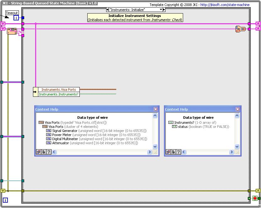
I currently have four pieces of code (which could turn into 5, 6 or more pieces in the coming months), I want to run or jump selectively according to an array of Boolean. I have a cluster typedef of numbers, which are each refers to a port VISA number connected to a particular instrument. This will be expanded in the future as the software is necessary to control the instruments more. There is an array of Boolean (coming from the vi) attached which has a value of TRUE for each instrument that was detected (and therefore is connected). In the case below, I want to initialize each instrument that is connected, but not try to do something for those who are not.
The cluster and the Boolean chart is shown below:
As someone who will need to expand in the future on this section of code, I want to write it in a way that will be infinitely extensible, without taking more space BD. At the moment I find myself unable to do since I do not know how to pair the table of Boolean with the elements of the bunch, such that I can run or ignore the code accordingly.
Help, please!
-James
Since you mention that you want to expand, I'd be more inclined to set a dashboard containing the port number, the type of instrument and the status of the instrument. When you search for your instruments you want to iterate over the array. You can use an ini file to determine which instruments must be present in the system. Others may be optional, and their associated actions could be ignored if necessary. However, the main point I'm trying to do is to combine your status with your instrument information table. This way, you eliminate the possibility of a mistake trying to keep and table and a synchronized cluster. A table makes it also much easier add or remove instruments from your system.
A few other notes, if you check in a stop condition then stop. Don't simply continue the execution of each iteration of the loop with a business structure that will jump execution if the stop consifition is encountered. Simply stop. Imagine if you had 1000 items in your instrument cluster/table. Using your method always run you your loop 1000 times, even if the shutdown occurred during the first iteration. Eliminate duplication of code and logic twisted to combat it. You have two places incentive th euser, if they want to start or stop. You must have a place to make this code. Much easier to understand and maintain. Don't expand your code easily either because the hard-coded error strings. Your case statement will become very large if you generate your static error strings. Use a loop and a format common you build your missing channel of the instrument. If you use the table on the groups of instruments, I suggested that you will be able to format the string using the type of instrument. I'd be much more inclined to use a single notification utility that will be supported as well cancel and stop messages. It changes a lot better when you have additional message types rather than use a notification for each type of message.
-
FireWire Camera disappeared to MAX when you select the driver NOR-IMAQdx
Hi, as the title suggests, I'm having a problem getting my camera firewire (a PixeLINK PL-A742) appears in MAX so I can use it in my application. First of all, a bit of history.
It was all works fine on an old computer (Windows XP SP3, LabVIEW 8.6.1, NOR-IMAQdx 3.2).
We just received two new computers. They have Windows 7 Professional 64 - bit installed on them, then we are stuck using that (I was going to install labview in XP Mode, but there is no support for firewire, which no longer works). After finally getting installed labview (to run the setup.exe from Distributions\LabVIEW-ENG\LabVIEW861\, rather than make the autorun) we cannot get this camera to work. It works very well with the PixeLINK pilot (and Capture OEM program that accompanies it).
So here is what I tried, and what happens when I do.
(1) install cost of LabVIEW (including IMAQdx 3.2) and PixeLINK drivers.
(2) at this stage, the camera works very well in the PixeLINK application
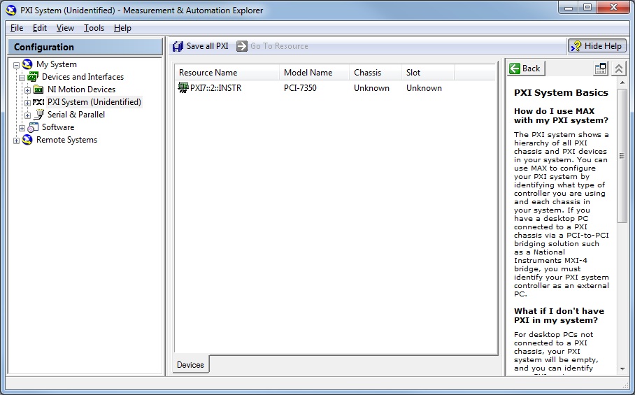
(3) start MAX. It detects the camera and shows under devices NOR-IMAQdx. When you click on the camera, it informs me that the selected device is not currently associated with legacy OR-IMAQ driver IEEE or the driver OR-IMAQdx. This is perfect, it is supposed to do.
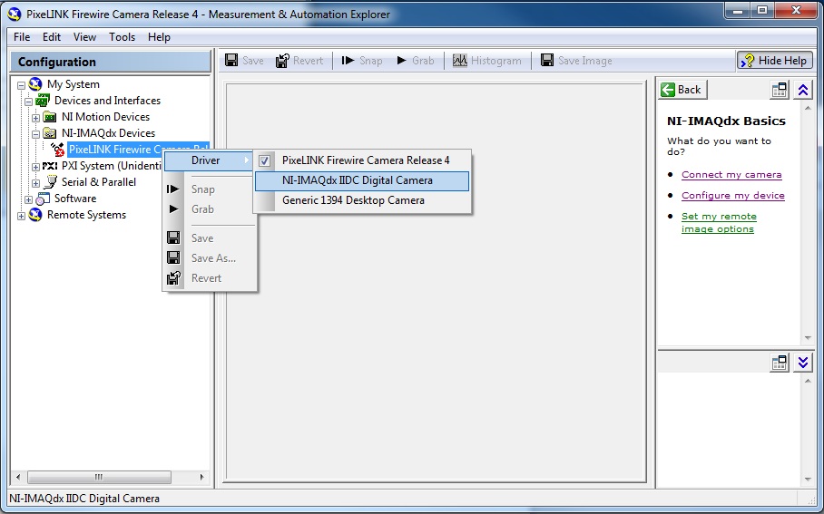
4) click camera > driver > choose NOR-IMAQdx IIDC camera digital
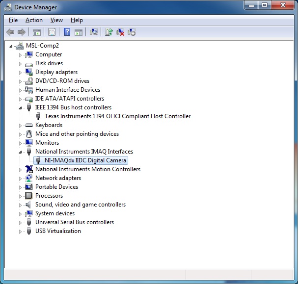
(5) he then disappears from MAX (no record OR-peripheral IMAQdx more). If I goto windows Device Manager, it comes under National Instruments IMAQ Interfaces as NOR-IMAQdx IIDC camera, says the pilot did get properly, it just does not appear in MAX more...
(6) at this point, there is nothing I can do to get it back to the MAX (except in Device Manager to switch the driver on the PixeLINK one, then he pops up and we return to step 3)
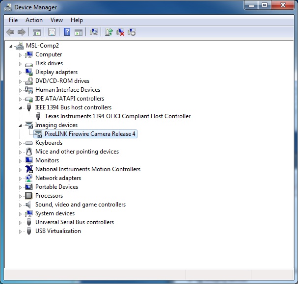
So, any ideas? This could be a problem with firewire interface and not the camera? I use the FireWire on my computer. It presents itself as Texas Instruments 1394 OHCI compatible host controller in Device Manager.
Here are a few screenshots to help illustrate my problems.
It is the initial configuration using the PixeLINK driver.
It's MAX with the PixeLINK driver
As soon as I click on the NOR-IMAQdx IIDC camera, it disappears
And here's what it looks like in Device Manager after you have selected the NOR-IMAQdx driver
Anyone have any ideas? I'm open to anything. At this point, I'm completely at a loss to know what to do.
Thanks in advance,
Devin
Mechanical engineering intern
University of Victoria
Well, you can just ignore this message now. I solved my problem. I installed Vision Acquisition software 2009 and it seems to have solved my problem.
-
low sound on Classic FM and BBC
My Office CQ5304UK behaved immpecably in recent years, but only in the last two weeks has developed a problem with the sound levels.
The sound card is an M - Audio 2496. When I play the Live BBC Radio 3 the level is down to-50 dB on 2496 meters and is of course very low playing through my Tannoy 5A monitors. It is however quite clean and noise and distortion-free. On another W7/64 office levels are at-20 dB with peaks at-4dB. This is also the case on another XP machine.
Sources of YouTube read to near 0 dB and all my recordings are at the right level. If I go to the archives of the BBC sites THAT music is at the correct level. It is simply live sound that's not going to. The same problem is with Classic FM live.
I got just this computer I have of course blame the BBC and CFM delivery system!
The CQ is also bad from a Native Instruments KA6 interface levels.
I am really confused!
I managed to get rid of re installed Flash and re installed drivers of 2496, all without effect.
Dave. Northampton UK.
The problem is resolved. It's to do with the Radio Player app on the BBC website.
I do not see how to attach the screenshot for those who want to know enough to go!
Basically, there is a small "speaker" icon Now, I flew over, left and this a dozen times right click in the last week or Yes but she either does nothing or it completely mute.
However, a guy at the forum www.soundonsound.co.uk found that if you "sneak up" on the icon to the right it suddenly gives you a volume control! But! Only while the mouse cursor is in preeeecisely in the right place, twitch and you miss. After a little practice, I was able to adjust the level back to 100% and everything is beautiful and neggerty 20 once more!
One of the guys at sos .co is a grad BBC ex' engineer and even he said he found the stupid and obscure funtion. Some time ago the BBC will display an icon of volume of style "ramp", but those pesky coders SHOULD keep things "better" aren't they!
Thanks to everyone for their contributions and abstaining.
Dave.
-
Information required to communicate with the instrument of the IEEE-488 Interface.
Dear all,
I have an instrument that has interface CEI-488. I would like to connect to my laptop using the GPIB-USB connector of NOR.
In order to communicate with the data of this device and the manual, I have a licensed version of LABVIEW. But when I made contact with seller OR I learned the connector would cost me Rs. 40000 /-including software as described in the web.
Is question 1 - necessary to buy the software with connector? or can I manage to read through LABVIEW?
Question 2 - I read the manual of the instrument and it can be programmed using the interface IEEE 488.2 measure of LABVIEW and automation Explorer can do this by using the existing LABVIEW.
Looking forward for a response.
Kind regards
Srini
Hello
If you have any material of LabVIEW and NI GPIB software VISA is free.
What instrument (model and seller) you are trying to contact?
-
Instrument interfacing in Labview
Hello
I would like a Luxtron m600 optical fiber probe so that I can use it to receive entries analog signals to control the heating of the samples of the interface.
My obstacle becomes the sensor FOT to contact my office. In MAX, I tried to configure the NI PCI-6229 I use under "Devices and Interfaces" with the probe attached to the block connector with wire bare but couldn't create the task. My understanding is the sensor FOT being a third-party tool, I also need to connect it to one of the serial ports on the computer by using a VISA interactive control. In addition, I also need to download the driver specific to the probe.
I downloaded the mentioned software and managed to obtain data on the temperature of the sensor with the driver. But my goal is to integrate these data at a higher level VI which will use the PID toolkit. Before, I used a USB DAQ Mbps key and had to use the explicit input function DAQ helps acquire signals. But for this application I use assistant DAQ and the Assistant of the Instrument, or is it a different thought process that will allow me to interface with the PCI-6229 FOT sensor lead? I've only been using Labview for a few weeks to get the detailed procedure would be greatly appreciated. Thank you for your time and patience.
I have attached the driver I downloaded for reference.
If you are unsure how to add devices to the connector pane in LabVIEW, you really start the tutorial from LabVIEW. Very basic task which should not take more than 60 seconds.
Throw the instrument if you want to instead use the DAQ card to read the sensor. Makes no difference to me. Always plug your DAQ card for what will be the heating element. Your reading of the temperature is only half of the installation. Since you already have this part done with driver, I don't quite understand why you focus not on the part of output control.
-
How can I specify VISA as the interface of the wizard of IVI instrument driver?
After a long hiatus and to reinstall on a new hard drive, I resumed an IVI driver development. Previously, when I experienced, I was able to generate a driver that uses the API of VISA.
Now, on this new installation, when I start the wizard, the only choices I have are Gbspecifications FOR, serial and VXI (message and registry).
How can I specify VISA?
Hey Frog,
As this measure Studio LabWindows/CVI Instrument Driver Developer Guide , VISA i/o interface is the mechanism through which the pilot communicates with the hardware of the instrument. The IVI Instrument Driver Wizard allows you to only select among GPIB, VXI and series more specify the interface for your instrument.
I hope this information helps!
Maybe you are looking for
-
can I install firefox on my new Tablet nook and if so... How?
Just got a Nook tablet as a gift. Still trying to understand it, never having any mobile device. Is it possible to install Firefox on my Tablet? If so, how should I do this? Thank you!
-
Upgrade to Windows 10 on HP series VK010PA #ABG
Before I even try to upgrade to Windows 10 I tried the weebsite indices if HP my laptop current is capable of runing Windows 10, but it was without help even after inputing the 11-digit series. Anyone have any suggestions other than to give it a try
-
M/S using wireless keyboard 800 and some characters are not displayed correctly
Have just connected a new wireless keyboard M/S 800, and some characters are not displayed correctly. For example, I get "when @ (update 2) is pressed on the keyboard and the £ runs it shift 3.» Am currently using XP SP3. No problems with my original
-
CD/DVD not detected or does not, OS-Vista (Home), SP1.
Laptop HP Pavilion DV700, OS Vista Home Premium, SP1, CD/DVD not detected and does not. Please advice. Thank you.
-
EliteBook 8570w: upgrade the workstation database model Mobile here 8570w
So, I want to upgrade my EliteBook 8570w. It was a school issued laptop that I have the opportunity to keep or "modernization" of the year next to the Zbook. The Zbook we saw, and frankly it's a slope down what I have now. That being said I'll opt