Interpolate color ramp
Hi all
for a digital with a slider, what is the different between the ATTR_COLOR_RAMP_INTERPOLATE attribute and the GetNumericColorRamp (, & Interpol2)?
They are the same or independent of each other?
If the first case, why have duplicates and if the latter, what is the difference?
Thank you
There is no difference. They both access the same data. We provide the accessor functions for attributes that are frequently used for convenience and readability. You will also notice that the accessor function retrieves several associated attributes.
Tags: NI Software
Similar Questions
-
Can I change the shape of a color ramp (I do not want a square but a heart)
Hello!
I want to know if we can change a color ramp, because mine is a square and I want to have a heart.
If not, perhaps can I load a picture (of a heart) and change its color depending on the input data?
Thank you!
want you a heart? (I hope that's correct
 )
)In the attachment is what you want.
How I did it:
-in Photoshop (you can use something else), I created an image, crop the middle like a heart, create a new layer and save it in GIF format. It is very important to save it in gif format because it allows transparent areas of the image. Save as bmp will fill in the middle with white.
-Open your cover and (using the mouse) drag-and-drop the gif file created.
-Add the 'color strip' (make sure its size to mount to the heart), bring back the front image and send "color ramp" (there are a few buttons that allow you to set the order of the controls and indicators - front or back on the toolbar)
You now have your heart.
Paul
-
Color codes of kml (google earth html) generations of color ramp
I am looking for a better way to take a digital input and generate an html color code which is compatible with Google Earth color codes. The included example works somehow, but it's slow... it seems to need a delay between the writing and reading of the band of colors. Complete to be of the form Codesseem
oobbggrr
where oo is an opacity of 8 bits (00-FF)
BB is a code Blue 8-bit (00-FF)
GG is a green code of 8 bits (00-FF)
and rr is a red 8-bit code (00-FF)
Any suggestions?
It's worse than you thought. I was playing around with your VI for a bit and found out that when used as a Subvi and with closed front panel, the result is false. I recoded the VI based on your second version using the property node Value and discovered it works much easier. He didn't need a period of time, and it seems to return the correct values that the façade is open or closed. See the example attached to see what you think. A rather "interesting" behavior of the command of color ramp.
-
Convert 2d table in Jpeg format with intensity color ramp graphics
I have a chart 2d of some size m x n I want to convert a jpg with the same resolution (IE, I want the jpg to have n x m pixels). I view this table 2d in a graph of intensity. I am currently using flatten pixmap to convert my table 2d in an image and then saving it as a jpg file. Unfortunately the colors don't come out like I want. If I try to use table of colors in the graph of the intensity of the colors come out correct, but erroneous values are associated with colors. I want the color scheme to match exactly what I see on the screen in the graph of the intensity of the jpg, but I want the full resolution of the 2d array.
I've attached an example of what I'm doing. IntensityGraphColors.vi has a chart showing the table 2d with a color ramp special z-scale, this just vi takes the 2d table and the table of colors on the graph of the intensity and records them in a jpg of intensity. But when I save a jpg file colors come out different, as shown in test.jpg.
Thanks for the help. I tried searching for similar questions, but could not find any solution that did what I wanted.
Here is an example that goes from black to blue to white, which will tell you if all goes well in the right direction to do what you want with the entrance of "colors".
Please note that the colors entry is ignored for the 24 bits of data.
-
The scale of the maps of intensity color ramp
Hi all
I use a graph of intensity to draw the characteristics of an ultrasonic field. The measured values expand a range between 3, 0e-6 up to 12, 0e + 0, then I need a very well detailed verry color scaling. I found a beautiful image (http://zone.ni.com/devzone/cda/tut/p/id/7664) joint as an image "colors ramp.jpg precise", where the band of colors is reduced by the black-> green-> white-> blue-> green-> red. But with the "color table generator.vi" caused by only three points of features for each of the colors red, green, blue, I get only a scale like on the second picture "rough color ramp.jpg. It is not possible to scale of the ramp from black to green to white, then again for blue, green, red.
How can I get a color ramp as in "precise color ramp.jpg? I guess I need the possibillity of each of the red, green, blue nationally on more than three points.
Thank you very much in advance.
Hello...
I found the solution in http://decibel.ni.com/content/docs/DOC-9294.
The "Color Table" exit (U32 data type table) Create Gradient Color Ramp.vi can be connected to a node property graphic intensity with the property "color tbl".
Now, the ramp can be fitted with various colors, for example now a color tone can be used twice on the bottom of the ramp and the middle or on the top of the ramp again.
:-))
-
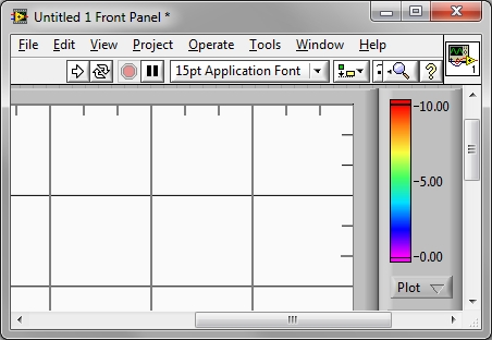
Track 3D color ramp - color values
Hi all
The color of the 3D locations ramp shows only 3 values; not all the values for each color appears (see below).
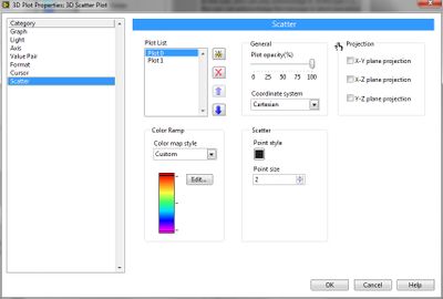
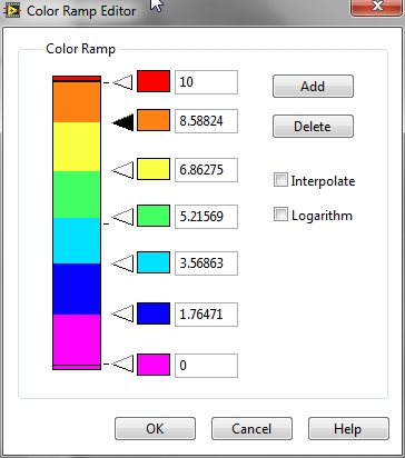
The actual values associated with each color is available through the properties of Plot 3D (during edit) dialog box.
How can I access values for these colors programmatically such that I can display to the user?
Thank you
Battler.
-
color of the digital meter ramp or slide is missing the performance
Hello
I, m using CVI 2010 (10.0.1. (419) on windows 7-64 bit.
In a simple program, I use a digital meter. I also use the color of the digital counter and on the IUR ramp, I see the ramp as expected with the defined colors. But when I run the Panel (in the debugging or mode of publication), the instrument (meter) shows but without the color ramp. If I save the uir file, close it, then reopen it, the ramp of color in the file of the IUR is also missing, so I have to configure it again. It's the same with a digital slide.
I think it's a bug? Someone at - it the same problem?
Greetings from bremerhaven
Norbert
My guess is that you have inadvertently saved the. IUR in an old format (8.1 or older). In the user interface editor, check the bottom right of the window to see what the current format of the. IUR is.
If this happens, you will have to change via file > save as.
Luis
-
Hello
I'm tracing a 3-d chart using the help of ground surface 3D and it works fine, but color ramp values adapt to my data. My question is: is it possible to change the values of the color ramp?
for example I have a color ramp between - 92.4 and - 85.9 and I want to change it (while the vi is running) to something like -100 / 0.
Thanks in advance
Hello.
The answer to your question is no. You cannot change the values Max and Min of ramps of colors, you can only add ladders division, and this is because the function gives you the Max and Min of your 3D chart values. You can see for yourself by right-clicking on the surface of the front wall 3D > 3D Plot properties > Surface > color ramp > edit. Otherwise, there is a way to change the X, Y, Z scale and see the part of the chart you want. Refer to the example below.
Concerning
-
the meter (knob), how the scale can have ramp red on both ends
Hello
How can you have the ramp of color on the scale of a meter (rotating flag) being red on both ends and green in the middle. I tried all the possibilities, and I can only do Red only on one end. If anyone has an idea how to make red at both ends, it will be a great help. Thank you
You must play with the bookmarks. It is not totally intuitive. You must first turn off of the interpolation of the color ramp. Then, you must assign markers to arbitrary spacing. You can then right-click on each marker and set the color in this section. Here is a page using LabVIEW: http://zone.ni.com/reference/en-XX/help/371361B-01/lvhowto/changingthecolorsofacramp/
See attached example (LV 8.2) for a result.
-
I'm trying to understand the features of the entrance of color vector of the new line of graphics path 3D VI, in combination with the graphics property 3D color surface map. Unable to find any documentation on how these default or overwrite each other or how to use. I thought that the entrance of vector color could be used to define a color directly to form a 1:1 correspondence with the entrance of z-vector, but that doesn't seem to be the case.
I used successfully the band of colors of a graph of intensity to change the color of the line 3D gradient, as shown in several examples of the graph of CW3D. However, when I increase the range of colors by changing the values min/max on the color ramp, the 3D line should then also show only a subset of the spectrum full color ramp. I guess this should be possible using the vector color and/or color map property somehow?
Thanks in advance,
Dirk
From post # 7 of this thread , you will find a series of messages that were intended to serve as a worst case introduction on the CW 3-d chart.
You will find the text to go with these images in this thread.


Ben
-
Colors in CS5 do not display right... ?
I usually use CS4 at school, but I'm doing something that is due tomorrow, and I was able to download CS5. It seems that this is pretty much the same thing, but I can't get the colors to work right. It seems that he wants everything to be in CMYK, but I am more familiar with RGB. As I try to make a square with R = 0 G = 255 = 0, if it should appear as a bright green, just like this, but it turns out really dull, more similar to this. It has a similar effect on all colors. The colors only, it does not appear to affect are the pre-made nuances. But if I try to make my own shade, he still has problems. Although, if I do a CMYK swatch, it works very well, but not all the colors seem to be available with CMYK. Bright green, for example. Red. Cyan. Blue. Yellow. All the basic colors. I can't use them! Help!
You can set the colors in RGB or CMYK. In the color Panel, choose the mode for cursors and the color ramp in Panel context menu. From the Swatches palette, choose new swatch of color... and define the type of process and the color on the model mode desired.
If you work in RGB, you must also change > merger of transparencies space > statement RGB.
Is this going to print? These really bright colors can be produced in print without using spot color inks.
-
How do you prevent PDF presets to alter the quality of the image
Experimenting different PDF presets, I noticed with grayscale images in Photoshop, save to PDF using different presets, change image quality, more precisely the contrast.
So, it seems that saving an image in the 'bad' PDF preset could undo a lot of pre-press work. Is there a better way/format?
To get an idea of brute: there is a decrease of 8.7% in the percentage of black between 10% and 50% of the values (the beach) on a corner of the stage between the original in Photoshop and PDF high quality, who showed the same values, and PDF/X-1, which has compressed the range of 4 (about a decline of 8.7%) percentage points.
A visual assessment and idiosyncratic, four versions of the same image (Photoshop in grayscale, High Qualtiy PDF, PDF/X-1a and PDF/X-3), which included a step wedge and the color ramp, would rank the fidelity to the best original, high quality, at worst, PDF/X-1a.
The same image to grayscale in Photoshop CS6 was distilled (file > print > Adobe PDF) to PDF using without changing settings predefined PDF in distiller Acrobat XI.
The screenshot next composit (all four images images on the screen copy screen, rearrange them, and then reduce the image to a 120 dpi to 4.2 "wide (including the text) gives an idea of the differences, but much was lost, it's here.)

Walton
I can't pretend that it's simple. There was a lot of choices to accommodate the many different requirements of professional pre-press. Same people experienced can fight to get the color corresponding to the work because they know that it should.
The key thing to remember is that in the color management, it is never a profile in question. There are always two (or four, or six...). One, the source profile, described the colors in your document. The other, the destination profile, describes a device. This device could be the screen that you discover on the printer you are printing on, or a device that is simulated.
So, by looking at three PDF files on-screen.
'High quality '. Source: mast 20%. Target: your screen. It's probably closer to the color displayed by Photoshop, which will do something similar.
PDF / X 3. Source: mast 20%. Target: output mode, coated FOGRA27. Then you must convert more using two profiles to see on the screen.
PDF/X-1 a. DeviceGray (no marking). This (by the rules of PDF / X, but not PDF in general) is the gray channel of the output mode, coated FOGRA27. So no converson up here, but it will be converted using two profiles to see on the screen.
Why FOGRA27? Because you him to choose, or in default, in your settings to distill. This is not a good idea, unless you know that it is the correct output for your printing needs device. This information must come from your printer, and you can't do really good PDF / X files without it. If you choose at random, you can expect more and unpredictable color changes.
-
How can I remove a section degraded in CS6?

In Photoshop and Illustrator, I am able to delete the part selected a gradient simply by pressing the delete key. This seems not to work here, can someone tell me how to remove the section of my gradient aqua?
In your gradient editor, drag the unwanted color from the color ramp station and drop it (once you see it's gone).
To add a new color stop, click in the box just below the color ramp. To add a new opacity stop, click in the box above the color ramp.
-
I don't know how to use a light layer in After Effects CS4
 Hello
HelloI work with a lot of layers of texts and it is very trendy to put a thin layer on the text at one time or another, it also seems to be really good. But I looked on the net for tutorials and may not know how to use the light layer so that a light passes through a text from one side to the other. It looks like a flashlight through the text. I go to the top and choose > layer > new > light.
What is the color of the text changes (the part that is not shined on). How can I change the settings so that the color of the text does not change? Do you know video tutorials to use for a light coating?
Thank you for your time!
You might need two layers of light: ambient light to get the layer set a general spread of the light, then a spot light to create a moment strong. Adjust the specularity and brilliance of the layer will also give different results.
If you try just to create a strong general time that rolls through the text, try instead the plugin CC Light Sweep. Also, applying a layer color ramp can create the illusion of some effects of light.
-
Border Panel and gradient background
Hello
It's probably very easy so apologies if I missed something obvious.
What I want to do is get a gradient background for the border of a Panel, then a different gradient for the background.
I tried to create a SWC from Flash CS3 file. It seemed he would work but when I added content to the Panel he placed the content on the title area of the Panel in the content area.
So I tried to create a graphical appearance using a box 26 x 26 pixels of padding in the appropriate color ramp, but it only would allow me to set the skin for the background and a border together and this isn't what I want.
When I watched the video on Adobe TV to do skins graphic I also watched a programmatic skin topic that looked like, it might be useful, but it sounds very complicated and I was wondering if someone could help because I'm quite at this news.
Also, if there is a simple passerby so please tell me I would be very grateful.
Thank you
ChrisHi again
Just found another post on this forum for a slightly different question, but what it boils down to is that it a bug and Adobe will not remedy.
The solution is to BorderTopPad the Panel to a value that takes the content in the header bar, and it works.
Wish that they had set even if, as many people seem to have had the same problem and it does not lose much time (2 days in my case) try to solve a problem that doesn't really have a good solution.
See the site:
http://dougmccune.com/blog/2008/01/17/followup-about-Flex-Panel-bug/
Hope that no one else lost too much time on this - if you did sorry and thank you.
See you soon
Chris


Maybe you are looking for
-
I have a new modem and you want to configure my Apple Airport as a backup drive; How do I do that?
I have a new modem from Verizon and want to configure my Apple Airport as a backup drive; How do I do that? I need to extend the network, simply find a use for the airport.
-
HP Pavilion p7-1210 door Desktop optical drive is not closed
This gate used to stand firm, covering an expansion Bay empty. Now it has opened and remains open; won't stay closed not so closed manually. My guess would be a kind of lack of jurisdiction, but I don't know how to take apart and locate the absence
-
4480 printer deskjet lost installation CD
Unable to print online out, need to uninstall and reinstall but don't have the cd to do this. also having the problem with the code 10 adapter tunnelling Teredo Ms... uninstalled, restarted and reinstalled and still code 10... Help, please... THX!
-
age of empires III download... what I need to make the game load on windows 7
Remember - this is a public forum so never post private information such as numbers of mail or telephone! Ideas: You have problems with programs Error messages Recent changes to your computer What you have already tried to solve the problem
-
Hi all I'm in Torquay in the State of Victoria - Australia. I'm running a 64 bit, Win 7 o/s. I have this PC protected by password that worked fine until yesterday. We have an intermittent failure of wiring that unfortunately seems to affect the circu