Is a TC must be wired?
I'm sure that the answer to this is 'no' until yesterday that is what I had.
I installed a new router today (a Homehub BT) and have lost my Time Capsule. It used to be like that on my network:

But now, the best I can do is get on my network, but via a Ethernet cable:

All I want the time Capsule to do is up to my Mac. That's all - and he used to do wireless. Now I can't set it up without the ethernet cable. I hit the button remains low on the TC today unites several times that I care to remember. I literally spent all day this.
Help, please!
Please see your other post.
Tags: Wireless
Similar Questions
-
You must stop your request before the engine may stop
I have an integrated application that uses LV DSC 6.0.2. The application starts and stops the engine tag programmatically. The application works fine, but on some machines, I'll get continuously the next dialog box when I try to stop the engine of the tag:
"You must stop your request before the engine may stop"
It's strange, because it only happens on some machines (it seems that it can occur on computers with ONLY of DSC Run-Time installed, not the full dev system. DSC LV).
The dialog seems to refer to the application of 'control' which tries to stop the engine... it isn't telling me that my devices servers need to be stopped.
This dialog box does not seem logical, I should be able
to build an application that can start and stop the engine... and why I get this dialog on some machines but not on others?John Paul,
There are two points that we should ask ourselves:
1: you can have different loops while in your application where you read/write to and from the engine of the tag with the read/write Tag.vi. These screws has a stop of production which must be wired first the while loop. If you have cases where you do not connect this output to your time stop loop you could access the engine while you want to stop the engine in another loop with the Shutdown.vi engine. -> Make sure you have all drivers of DSC to access loops has stopped before you turn off the engine.2nd: I guess he was once an issue of race with the DSC engine condition and how it access to shared memory with the read/write Tag.vi. But this condtion of race must be agreed with the version of LabVIEW DSC
6.1 or with other fixes for LabVIEW DSC 6.0.2. You can download patches (in this case, particularly the BVRTDatabase.dll) driver update page & of NOR: www.ni.com/support/ > Option 3, drivers and updates > Search drivers and updates > type 'LabVIEW DSC' > choose LabVIEW Datalogging and Supervisory Control 6.0.2 fixes.
You must apply the patches of this as well on your DSC 6.0.2 Run Time System!I hope that one of the help of two suggestions to solve your problem.
Concerning
RolandFTP://FTP.NI.com/support/LabVIEW/labviewdsc/fixes/6.0.2/
-
Need help setting up a wired LAN lan games
I try to understand what I have to buy an easy to implement the cable LAN. Specifily more I'm looking for a router, switch, or hub. I will be putting this LAN up aboard a commercial ship so it must be wired (too much metal for an efficeint wireless signal) and I'll proably a 12 people who want access to connect to an Xbox 360 or PS3. This LAN will never have access to the internet. In the future there may be more people who would like a connection so I would have the possibility to connect two switches together (1 switch by the bridge of the ship). but for now I'll just implement 1 Platinum that I have only one available output to power a switch/router/hub.
Key factors
1. you are looking for something small price
2 you can connect at least 12 people
3. simple and detroit before implementing.
4 hold a model specific linksys product so I can read about the installation process. That way if I need to assign IP addresses, I can make it in advance and make installation as soon as possible.
You can opt for a router (8 ports) BEFSR81 or BEFSR41 (4 ports) followed by a network switch EZXS55W/EZXS88W/EZXS16W (08/05/16 PORTS). No need to put the IP address for the computers that you can use the DHCP from the router to the switch and the computers.
-
Lenovo Yoga 2 Windows Tablet stuck on the display "Hi there" after reset
In January of this year, who is traveling to the United States, I bought a Yoga 2 Tablet (1051F). I have used since then, even improved to 10 Windows. After this time, I decided to sell it, so I reset Windows 10 with the option to erase all. The process went smooth, took time. After restartintg, I was introduced to display "Hi There". Problem is: I can't click anywhere. I touch the option on the screen and nothing happens. I tried to connect a wireless USB mouse, nothing helps. I live in the Brazil, and Lenovo does not provide support for this product here.
What I tried:
-Leave the collection: it goes the same screen, same problem.
-Restart with USB flash drive: created a my another PC running Windows 10 recovery disk, but it does not recognize the tablet.
Here is the image of the screen at the moment. Did anyone been through this? Any help would be appreciated.
Simonjphillips wrote:
I have exactly the same problem. It doesn't have all the answers on the internet at all.I can reinstall win 10 but can go no further than the screen with language option as shown in the first post. In mine is an Indian purchased the Tablet, but I am English but I do not affect the issue.
Hi Simonjphillips.
I'm happy to report I have solved this problem and now, you may also like. All you need is:
-an OTA cable
-a USB hub
-a USB keyboard
-a USB mouse
I had to buy the keyboard and the mouse. Two of them must be wired; Wireless will not workYou can only use the keyboard if you want, and then you won't need the hub. This is what I have at the beginning (like this), but I quickly got sick using keyboard shortcuts and I had already bought a mouse and a hub USB lying somewhere there, I gave that a try and it worked.
Simple turn off the Tablet, connect the cable of the OTA for the micro-USB port, USB hub to the OTA cable and keyboard & mouse to the hub. Now, you can go through the initial steps of the installation.
The touch screen does not work at first. You can wait for Windows search and install the correct drivers or go to the Lenovo support site and download all the drivers. You'll need to first is one who says something "chipset". Install and it configures touchpad, bluetooth and screen.
Let me know if it helps.
-
The use of generate for demodulation and modulation PSK sync settings
Hi I'm trying to generate Parameters.vi of sync allows you to synchronize the flows recovered after demodulation and my input to the block of modualtion streams but I do not know how to work with this block to synchronize the input with the output stream stream. Also would you please let me know what are the modes of synchronization of the input bits and demodulation bit stream. I really appreciate your help
Thank you
Hi en99,
To use 'Synchronization generate MT Parameters.vi' you must wire in what follows on your block diagram:
- The parameters of the system created in 'System generate MT Parameters.vi' needs must be connected directly to the vi synchronization.
- Sync settings must be wired directly to 'MT Demodulate.vi'
- The bits of synchronization can be connected to synchronization vi directly at "MT generate Bits.vi.
What I did is took your 11. VI you downloaded in your post previous and amended to contain synchronization vi. I recorded as a 2010 version.
I hope this information helps!
Kind regards
-
Relay using the temperature control
Is there a code example using a TC 120 to control PS RLY 420 FP? I am trying to enable / disable a device by using the temperature.
The first problem with your VI, is that it is not executable for several reasons. For most various terminals that must be wired which are not. Click on the broken arrow of race and it will show you these errors.
I don't think you want to put your Fieldpoint writing in a housing structure. You should wire the Boolean Fieldpoint write directly. A true value turns on the relay, a fake he died.
Another thing that I see in your VI, it is that there is not the channels defined in the Fieldpoint i/o constants.
-
Storage of Information within the screw
I have an interesting problem...
I have a VI that controls a subsystem. It has about 80 entries, when he used the subsystem with these entries programs. Entries are not homogeneous, they are information configuration and each means something different. This VI allows interactively and as part of a larger system. Since it has many entries I used clusters of group related entries.
As far as I can say LabVIEW applies the following scope rules when SubVIs are involved:
Controls that are wired to the login Panel
When a top-level VI calls a Subvi if highest level VI son an entry then the Sub - VI receives this value. If the VI more high-level wiring is not an entry, then the default value is used.
Controls that are not wired for the login Panel
When a VI is loaded into memory front panel is loaded with the default values, even if the VI is not visible. LabVIEW retains the values defined by the last use of the VI. It goes the same for registry entries to offset unwired.
The behavior of controls unwired is useful because it allows information to be stored, it allos "masking of information." In my application I can open the VI subsystem described above in an interactive way and set up some values. Screw top level then call that VI as usual. These screws of higher level need not know anything about the settings I changed. Where I work, this idea is used in the code for many years. It is similar to the "functional global variables" using terminals unwired-shift register.
Once a control should be wired to the component connector however everything changes, a value may not persist a use of the VI to the other. This is true even if the connector pane entry is left connected because otherwise LabVIEW use it * default value * not the existing value. Thus, all controls dealing with things my subsystem-specific low-level can be left unwired. Then all controls dealing with things higher level that allows to control the higher level screw must be wired and the highest level VI must assume responsibility for this information. Previous versions of the system that I mention did.
The problem with this plan is that the clusters. A cluster is either on a connector component or not, I can find no way to put a cluster on the connector pane entries but not others. Since I have so many entries, I need bunches. But, once I attribute a cluster to the connector pane the top-level screws must take responsibility for all its values. This means that I lose all the concealment of information that I had before and my code becomes much more complicated.
Someone at - he found a solution to this kind of problem?
I can draw out as example screws if people are interested.
-
Adding items to an array of unknown size several times
Hey,.
I had an application that communicates with a device (a generator of microwave) via the Protocol modbus RS-232. It is within a state machine. The VI running generator initialization first and then move to the State 'pending', where I have a structure of the event to follow any value change of control. In the structure of the event, a timeout of 300 ms is implemented, because communication to the generator must be active at least every second (if not a defect is reported). In the case of timeout I read all record and display values.
Within this time-out I would record a value of the indicator ('measure Pfwd') several times in a 1 d table (the table size is unknown!). However, I would like for the variable to record only when the indicator 'MW?' is 'TRUE '. And "MW?" goes from 'FALSE' to 'TRUE' every time, I would like to start writing on a table from the beginning.
I tried several options, including the table to remodel, but I can't make it work. Or it works in a separate VI, but when I use it within the structure of the event and state machine, nothing works.
If someone has an idea, it would be welcome...
Thank you
Concerning
Create an another shift register which is initialized with an empty array of the correct data type and use the node Build table add data to it when you want that he added.
In BT, the size of a table doesn't have to be declared in advance.
Mike...
PS: other tunnels must be wired throughout.
-
Design practice nor 6008 USB DAQ
Hello
I have a few question, I'd like to introduce. I need some sort of indication on how to better perform a timed cycle of acquisition driven by WSF.
I'll send my VI (conceptual, not one currently working one) and ask for explanations.
The goalI need to acquire a battery voltage. Load current consumption is driven by a couple of transistor. I drive the hollow transistors two digital i/o for USB data acquisition.
Because I need to have a power for a given time cycle, I need to have some sort of time control on the output.
So I wrote a simple state machine whose States are updated when a timer reaches zero. Each State has its own queue time.
Moreover, I differentiate between acquisition and control operations using two all in cycles.
First question: is this a correct way to a timed WSF of construction?and now:
The problem (s):
I need to connect and establish a correlation between the input line for the internal of the fsm States. So I madesome digital indicator on the face before of the VI and created a local variable (I know that local variables are BAD, but I had no other idea everything) to pass values for some time to the other.
I also want to select State sequent of the FMS based on the input value, I get a channel. I can stil use a local variable?
Are the two related tasks?
Second question: are local variables, something that I can use for this task?
Last but not least: I need to filter on the values.
In this vi I perform a filtering operation and then I get the I use for control of local variables.will be this filtering desync the two cycles while? will I run out of control before running the filtering?
The same question is valid for the purposes of registration: the unfiltered data record, I guess is unnecessary. But based on this 'architecture' I know the country reports and the recorded signals are out of sync (as happens in many game data acquired with this vi).
Is this a problem of logging (perhaps given by different buffers for data acquisition and internal State or something similar) or the whole WSF will be out of sync, then all acquired data is more useful because it is out of sync?Any advice would be much appreciated.
Best regards
Luca.
Luca,
Question 1: This is a reasonable start but need some things to make it a good WSF. There is no waiting or delay in the loop so it will run as fast as possible. U.S.-6008 outputs digital software timed so that the DAQ Assistant can take a long time, but the amount of time is unknown and not necessarily consistent from iteration to iteration. Since the DAQ Assistant Analog Input in the other races of loop to<= 10="" iterations="" per="" second,="" a="" wait="" of="" 100="" ms="" in="" the="" fsm="" loop="" seems="" like="" a="" good="" starting="" point.="" waiting="" 3000="" ms="" is="" not="" a="" good="" idea="" because="" the="" loop="" becomes="" unresponsive="" to="" the="" stop="" button="" for="" long="">
Do you need to write on the lines on each iteration, even when the data has not changed? Add a write state that is called only when the data changes.
The DAQ Assistant has a Stop input and an output of Stopped. When you are ready to stop the loop, the stop signal must be wired to these inputs so that the DAQ Assistant can delete tasks. The output of the order can be connected to a Terminal to stop the loop.
Problem (s):
It seems that you want to link the two loops. Local variables are usually a bad way to do it. The best way is to use queues. A queue can send the current state of the file loop. (More comments later if that's really what you need). Another line can send data, or better, the commands, the loop of the file to the loop.
I think you want digital output values rather than the State. Especially if you add a State writing as I suggested above, the current state will not always represent the condition of the power of your test. To make this work with the additional state Boolean matrix must be moved from one iteration to another via a shift register.
It seems that you have at least two controls to be sent from the loop of the file to the loop. One is the stop command. The other went to the higher power level control. You should probably have a command to set off power level which can be used if the battery voltage becomes too low and before stopping. How your program is currently configured, the last level of power will continue as long as the power of the computer is on and the USB-6008 is always plugged. The cessation program does NOT reset the lines.
When you use anti-parallel to the queues, you must be careful on the definition of wait times and the timed out case management.
The benefits of the queues are that it is easy to ensure synchronization at the level you need, the data can be stored according to the needs, and there are good examples. It also avoids the possibilities of race conditions, often introduced by local variables. This program could be based on a variation of the design producer/consumer model.
Filter questions: any filter introduces a time delay. In your case when you filter 100 samples 10 times per second, it is likely that the filter will do well until the next data set has arrived. The delay of the filter is not affecting your synchronization. The above lines will solve problems. Since you are looking at time of cycle seconds and the minimum interval on the order of 100 ms, the exact chronology (to tens of milliseconds level) is probably not too important.
The real question about filtering boils down to this: does the control work better if the signal is filtered?
- - - - -
I'd probably all this a little differently. Given the slow speeds and the small amount of data, a simple loop with an improved state machine is all that is needed. Get rid of the DAQ Assistant and learn how to use DAQmx screws. States could include: Init THE Init, Init File, Idle, read, write, DO, Analyze, filter, adjust the power, wait, Save, close file, DO, AI Shutdown Shutdown, error and exit. No variables. No indicator fake just to allow the creation of local variables. Very little code outside the structure State case. None of the queues.
Lynn
-
Hello
I had a question quite simple reagrding an error message that appears when I try to run a program PWM.
Basically, I am using a 6211 IO device NOR, and I used the DAQ assistant to configure a counter pulse output in channel Ctr0. I try assistant express VI wiring DAQ channel create DAQmx (CO Pulse Freq) VI by attaching at the entrance of "task in.
However I have an arrow broken run and the error message reads "sub - VI 'DAQmx Create Virtual Channel.vi' necessary entry 'meter'... The designer of this sub - VI stated that this terminal must be wired". In other words, he wants me my e/s physical wire at the entrance channel 'meter' rather than the 'task '. However, I don't see the outputs of the DAQ Assistant who are not focused on the task.
Any suggestions?
T
The DAQ Assistant creates the task for you; There should be no need to use Create Channel. Alternatively, you can remove the DAQ Assistant completely and do the work yourself. You can look at the code that the wizard creates by opening his Panel before (right click on the VI).
-
Apparent problem with OpenG Get Data Name_ogtk.vi
The data Name_ogtk.vi Get OpenG is a function that takes a data Structure and returns the name of this structure if the Data Structure has a name.
I use it in my Configure.vi. Configure.VI takes several data structures and saves / loads to an INI file. The name of the section in the INI file is the same as the name of the Data Structure. When loading, Configure.vi takes the name of the data structure to load and locate the Section in the INI file with the same name and then uses the items listed in the INI section to load the Data Structure with the data values.
In my case, I have 3 sections. Two of the sections, 1 Servo and Servo 2 derive from the same Type definition. I am trying to load 3 of the attached INI file data Structure. The Config.ini in the system file has been generated by the backup function Configure.vi. I'm passing in the routine of the load, 3 Data Structures, each with unique names. I have an explicit call to get the data for Servo 1 Name.vi and 2 Servo. But the probes on the output of the Name.vi of data values get two return to the same 'Servo 1' same string if sensors on the Structure of data entries that clearly indicate them the unique names of the "Servo 1" and "Servo 2" respectively.
It seems that the 2nd Get data name returns the name of the Data Structure 1 by mistake. If anyone can check this?
Does anyone know how to fix Get Data Name.vi so that it returns the appropriate data Structure names?
Thank you.
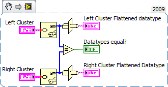
I was able to reproduce it and I show here as an oddity to force entry to the variant on the primitive flat string Variant.
Basically, if you have more than one cluster with content command to match the type and order wired directly to this function, it returns the flattened string which is first to each call. The wires must be wired without before converting to alternative, if you have points of constraint.
This only happens if you feed directly the input varying both and get the stress points. If you are using a variant is not the case.
I found that this occurs if the cluster is of type defined, and it does not occur for constants. I didn't try other controls. I'll be honest, I'm usually used to constrain to the Variant. I'll be more careful in the future!
----
so convert to first variant will solve your problem. In addition, if you leave the entry of the section name of the variant config openG write screw unwired, he will take the name as it is the research of the control, you did, so you need not the name of data Get there at all.
An excerpt from 2009. as - is equal to true. The bunches are each a dbl and a bool, but each FP different controls.
-
Open VI refers to a VI library project
Hello
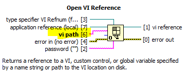
my code name some subVIs by reference using "Open Reference VI" and "Call by reference" live now, 'Open VI référence' expects a path to VI:
When the SubVIs sit in the same folder as the appellant VI, it is easy to simply provide the name of the Subvi. However, I want to call a Subvi, which is part of a project of library sitting somewhere else on the disk. I could give the relative path, but this make the fairly rigid code and if the relative path changes all paths will have to be changed. Ideally, I'd like to use the fact that I am using a library project. Assistance to open VI precise than reference
path of the VI accepts a string containing the name of the VI that you want to reference or a path to the VI that you want to reference. If connect you to a name string, the string must be delimited name of a VI in memory on this target. If you wire up a path, LabVIEW VI searches the memory that you have previously loaded this path on the same target.
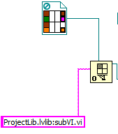
I thought that the path pointed out my ticket and tried something like this:
but it did not work and I got
"Error 1004 to reference VI opened in MainVI.vi:
Possible reasons:
LabVIEW: The VI isn't in memory.
To load a VI in open with the function of reference VI memory, a path must be wired for the entrance to the path of the VI. »Wiring of a path is not desirable according to the reasoning above. Is there a way around the problem?
Thanks in advance!
It should work, but you must pay attention to something that is indicated in the help and in error: If you use a string, the only way for BT to know what to access if that something is already "in memory" (sometimes also referred to as "loading"). In the case of the standard libraries, this means that the VI itself or one of its callers should be charged. In the case of classes and XControls, loading the library (as in having it in an open project) should be enough to load all its members.
What I usually do is use a static reference to a VI to get his name; that assures that he will be linked statically, included in the executable files, etc. Which may not work for you, if you want the dynamic loading and then you will need to use other means. Something I did when I needed something like that was to have a VI another which would always be in the same folder that the VI I wanted to load and then I had a relative path from that, but brings back you to the same problem where you might only screws.
-
How to get the index of a button in the control array?
Greetings,
I have 3 parallel arrays - buttons containing a and the other two indicators a string containing. I wish I could press a button and get the values in other tables. How is that possible?
(P.S. Illustrations are great and welcome, but I don't have Labview on this computer, so I would appreciate in jpg or screenshots if possible.)
Thank you!
Altenbach says:
Here's what I had in mind. Modify if needed.

If you have the buttons to all wrong initalized, then you don't need to perform the do not equal to. Just do a search with the NewVal. The local variable to reset buttons must be wired to the OldVal.
-
Out of reading 2-wire 4-20mA pressure sensors using the NI9203 module
Hi all, I'm sure that a lot of people can give a response would we apply for this.
While looking at the wiring diagram on some pressure transmitters (2 wire 4-20 mA output, direct wire), that I'm about to buy, I noticed a slight inconsistency with the wiring in the NI9203 manual. Here are links to manuals for sensors:
Following the manual of NI9203, the + ve terminal of power supply (24Vdc in my case) must be connected to the Brown Terminal in the transducer and - ve supply ground COM on the NI9203. This leaves the Green Terminal in the transducer must be connected to AI0... AI7 on the NI9203 module. This provision makes perfect sense to me. However, the user for the transducer manual suggests that the Terminal green must be wired to zero volts land i.e. COM. This configuration makes less sense to me.
My question is, the internal electronics of the transducer released still the same my current for the same measured pressure given by the curves of calibration for sensor, even if the Green teminal is not connected to zero volts?
I have a hunch it's okay, but I wanted to be sure before that I lost many years spent money / bad record pressure. This should be a matter for manufacturers of sensors I know, but I found this forum is * much * more useful!
See you soon,.
Chris
Hi Chris,
The 9203 is a device for current descendant be plugged on one side common or 0 volt. You must connect your pressure in 2 wire mode sensor.
+ 24 v DC to the positive terminal on your sensor pressure 1 terminal or brown flying lead, Terminal 2 green flying lead is connected to AIx on your 9203 and the commune of the 9203 connected to 0 Volts on your power supply.
All 2-wire device used in a current input down is still as cable + volts then 2-wire device + then then 2-wire device - (or 0) then HAVE + then common then 0 volt.
In my experience the 9203 can be rather prone to noise pick up devices with 2 sons and need a suitable clean power supply. For 2-wire devices, I take 1024 readings and then averaged to reduce noise.
See you soon
Stephen
-
Treatment of LabVIEW data and high speed data acquisition C
Hi all
I am designing a data acquition VI high speed of 3 cards acquition of data at the maximum speed. Data cards are PCI 2517 Measurement Computing. The sampling frequency for each card is 1 M samples/second, if the total sample of M 3/second of three cards. Problem is the LabVIEW drivers and the screws provided by the provider works very well just for a single card at maximum speed, but does not support multiple cards at maximum speed. Their technical engineer advised me to write code in c#, C++ or VB.NET for this data acquition high speed. If I use C forever, I would like to use LabVIEW for processing of the acquired data to data acquisition. I came across a few examples that suggest the creation of dll C code and then calling it a LabVIEW. But those who have programs simple and none of them speak in C data acquisition. My questions are,
1. is it possible to call a C data acquisition program high speed of labview and not work in any kind of present of buffer overflow?
2 would it not simple best to use labwindows CVI?
3. is there another alternative solution that I'm missing?
I'll appreciate all the entries.
Thank you!
Nilesh-
It's pretty easy. Arguments for CINrun must match wiring. You can wire your CIN function block and say LabView to generate the C interface code to begin.
Here's my pairs for the ASIO audio project.
All the best,
Terry
Maybe you are looking for
-
I found some bugs in the application Notes. (1) the research process will not match a term if it is part of an expression highlighted in the text of a note. (2) when you select a note in the list of the results of a search, the term you are looking f
-
I try to use AppleScript to control the speed of the slideshow on a G4 with Leopard. I don't have iPhoto. The following works well: Tell application "Finder". activate Select each file of (choose folder) end say Tell application "system events". key
-
Equium A60 199 SM Bus controller - where can I get a driver?
Hi, I am able to install the SM Bus controller, there seems to be no driver in the official site of the United Nations. Where can I get one? Can someone help? I use Win XP. Thank you
-
Low battery or endurance mode does not start
I use Xperia Z3 D6653 on Android 5.1.1 has a low battery / Stamina mode to start automatically at a set level battery. For example. 15%, 20%. My problem is, none of these batteries start to save me modes automatically to the value of drum set. I have
-
Extensions Manager command-line tool will not install extension for Photoshop CC 2015
I use Photoshop CC 2015.0.1 on a MacOS 10.9.5I try to install the extension FlatIcon found here: http://www.flaticon.com/download-plugin#Using the information I found here: https://helpx.adobe.com/extension-manager/using/command-line.htmlI downloaded