IVI Configuration with the PXI-4110 in TestStand
Hi all
Implementation:
PXI-1033 connected through MXI to a PC running Windows 7. LabVIEW 2014. TestStand 2014 (32 bit). DMM PXI-4110 food and PXI-4070.
In MAX, I can open two soft signs and two control units and they work great. In LabVIEW, I can control the two cards as well.
MAX I put in place a pilot and a logical name for my DMM. This unit works very well within TestStand using one-step IVI DMM.
I then configure the 4110 to the MAX with a pilot of the IVI and logical name. Here are my settings:
Name: ni4410_PS
Material: Immobilization of additional hardware and select the PS. This is checked, any other assets are checked.
Software module: NOR-DCPower, 4110 is listed as a device supported.
Virtual names: It is where I am confused, under the name of physics there are four options that arise (0, 1, 2 and 3). This power has only 3 exits, so I'm not sure why four rise. I've done 4 virtual names, one for each of the options. I named the ch0, ch1, ch2 and ch3 respectively.
When I put a power of IVI step TestStand, everything seems to work. I open the configuration window and set my values for each channel. If I try to validate the configuration by deselecting simulate and click init I do not receive an error. As soon as I click on 'Set up' or 'Show Soft Front Panel', I get the following error:
"IVI operation failed set to the name of lgical"OR PS 1'. Details: Possibility of Extention not taken care of by instrument driver. (Base) (- 30717) »
Any information would be appreciated. I tried to play with it for a few hours yesterday and a few colleagues trying to help. We are all under the assumption that it should work.
Thank you!!
Jesse
Hi jesserzamora,
Did you see this link: http://digital.ni.com/public.nsf/allkb/331F2717DBCD1F858625758200745773?OpenDocument
It addresses a failure similar to the step of IVI Power Supply of TestStand.
Tags: NI Hardware
Similar Questions
-
OR DC Soft Front Panel, minorbug, small bug with the PXI-4110
Hello
The NI DC Soft Front Panel V14.0, with the PXI-4110, scrolling to negative tension, works as expected to-10V, but then returns to 0. If we change from - 1V procedure, it goes...-8-9,-10, -1, -2... instead of-8-9,-10, -11, -12...
Everything about her, a simple thing that I miss is a switch for all three voltages.
(Also, IMO, it would be logical for negative tensions with the arrow pointing down, not more).
My 2 c
Hello Janaf,
I completely agree with two of your statements, I tabled a report of corrective measures that you can monitor in the next versions of DCPower to see if this is fixed with the FPS. CAR number: 512257
I've added notes that only manual insertion of numbers - less than 10 works and that it was not logical to use arrow increment or upward arrow to reduce the output voltage.
-
Acquire more than 2047 samples with the PXI-4461 instaled in SMU-1073
Hi all, I would ask you for help with the buffer limit.
I intend to buy digitizer PXI-4461 and he instal in SMU-1073 chassis, namely control via MXI Express of Labview installed on a separate computer.
What I need:
-to acquire data of a single channel of AI, but at least a sequence of 20 kS by a acquire task, in some situations until 200kS by a task to acquire.
The question:
- I can gain more than 2047 samples in a single sequence, like 200kS, with the PXI-4461 installed in SMU-1073?
Internal buffer of the PXI-4461 is reserved to 2047 samples. So I'm not sure if Labview can download remotely via MXI Express the data in the buffer of the PXI-4461 via MXI Express fast enough without any affection of the sampling program.
-in the case, this PXI-4461 with SMU-1073 isn't the right combination, what chassis and a controller can do?
Thanks much for the reply
Jan
It will work for you.
The on-board buffer 2047-sample is used only as a backup if the flow of data to the PC host (via MXI Express in this case) is not fast enough... that it will be (explained below). DAQmx transfers data from the buffer of the device to the host PC as fast as he can and, in ideal conditions, should not save the buffer 2047 much at all.
Let's just say you get 110 MB/s (randomly from a MXI data sheet) flow on your MXI connection. The 4461 has 2 analog inputs, which will be at 24 bits, we just round 32-bit in case it transfers the data in this way.
4 bytes/sample (32 bit) x 200,000 s/s x 2 (channels) = 1.6 MB/s, which is well below the 110 MB/s, which will make the MXI link.
clear as mud?
Germano-
-
Pulse modulated CW with the PXI-5650 and PXI-6653
Hello
I'm trying to generate a signal CW of pulse modulated with the PXI-5650 as source RF and the PXI-6653 as the modulation signal. Basically, I'm trying to generate a simple radar waveform. It seems that it would be possible to use the synchronization Module (6653) to transform the RF output on / off on the signal generator (5650), but I do not know how to route the signals from one to another using LabView.
Has anyone tried this or something like this before? Can anyone please offer some advice?
Thank you!
-John
Hi John,.
Reading your post, it seems you want to use your calendar and map of synchronization to the RF output power, in other words, on Off Keying. OOK modulation is a feature built into the 5650. For more information, you can navigate through the NI RF Signal generators Help for devices-RF signal generators > NOR -> NOR 5650/5651/5652 overview-> Modes of Modulation and simply click on the Modulation Modes.
An example of this is found in the example Finder OR by navigating to the help-> find the examples in LabVIEW and then navigate in the Finder to example NOR material input and output-> Modular Instruments-> NI - RFSG-> signals-> RFSG 565 x Digital Modulation.vi.
Kind regards
Jason L.
-
What pins to use to receive the data from the PDS ELITE RS485 with the PXI-8431/2?
Hello!
I use the PXI-8431/2 to read data from the flow meter PDS ELITE (Modbus RTU). Receiving data, the RS485 protocol request to terminals 4 and 5, but this configuration does not seem to work. When I connect the RS-485 converter USB of Microflex I get the data correctly, so somehow between the PIN lay and PXI this problem there.
Can someone help me?
See you soon,.
Steven
Hello Steven,
I think that what was Hossein trying to send you is the following:
How to connect and configure a device with RS-485 2-wire
Can you also tell me a little more what you use to read the data? What environment. You have 2-wire or 4-wire Modbus RTU?
Kind regards
-
Hi all
play with a digitizer PXI-5124 in a case of PXI1042Q with a PXI8110 controller that runs labview 2012 (latest updates) with the latest version of the driver NIScope.
I put in place an acquisition of off-delay (by assigning the triggering delay, for example 20us) which works very well (I can tell by the signal I get delay control works correctly), but the data returned in the info wfm cluster (using the 2D version of niScope I16 Fetch) does not have this delay.
Description of the relativeInitialX within this cluster indicator indicates "is the time in seconds between the trigger and the first sample in the acquired waveform" but its never to return something around 1E-9 independent of trigger delay. Surely the relative initial x should reflect the triggering delay?
I'm doing something wrong?
Thanks for your help!
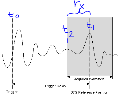
So, I made a screenshot of the image in the section "Trigger Delay" link I sent you.
Meaning of the symbol:
T0 = original moment of relaxation
T1 = time to trigger used in the acquired record (t1 = t0 + TriggerDelay)
T2 = time of first sample in the record of the acquis.
RX = relativeInitialX = t1 - t2
Response to previous reviews
«I understand what you're saying - so basically, if I want to know the delay of my trigger for the first sample in the record, I just add my delay time value to the relativeInitialX.»
- Close, the delay of the original trigger (t0), for the first sample in the record (t2), would actually be TriggerDelay-relativeInitialX
«.. . Nowhere does graphically describe where is the relative value of initialX real. »
- Right, relativeInitialX is not a timestamp, so it is not a place on the timeline, it is the difference between two timestamps (t1 and t2 above), where the relativeInitialX name.
"The trigger"record"is the straight line in the Middle, so expect relative to - 1/2 initialX record length?
- Almost correct, because the reference trigger is relativeInitialX to the position of 50%, will be the time in seconds for 1/2 the record length. (i.e. If the registration has been long relativeInitialX, 2s = 1 s). RelativeInitialX will always be the delta time between the trigger (t1) and the first sample returned in the record (t2).
- For example using the picture above: If t0 is 10 sec, Trigger Delay = 3 sec, SampleRate = 1 kHz, = 1000 record size. This means that t1 = 13 s. Our record is long of 1s (1000 points to 1 DC between each = 1 s), if t2 = 12.5 sec. If away from all these moments are absolute time, as the timestamps. So relativeInitialX = t1 - t2 is 13-12, 5 = 0.5 sec.
- As a side note, the reference position should not be 50%, you can configure to between 0-100%.
Time not yet discussed record attributes
I don't want to make you more confused, but there is another useful attribute in the waveform info that we've not yet discussed and its AbsoluteInitialX. Starting from the NOR-SCOPE help file:"absoluteInitialX is the timestamp of the first sample of recoveries in seconds..." "So, using the above image, absoluteInitialX = t2.
I hope this helps. If a part is still not clear, let me know.
-Nathan
-
Current limit for the PXI-4110
I'm a PXI-4110 with LabWindows programming. I'm trying the current limit. I have an output to 5V with a load resistance of 1 K; This makes the current 5mA. I put the current limit of 2mA to work. When I read the voltage and current is 5V 5mA. Here is my code:
g_voltageLevel_ch0 = 5.0;
g_currenLimit_ch0 = 2.0E - 3;
status = niDCPower_ConfigureOutputFunction (vi_4110_0, channel0Name, NIDCPOWER_VAL_DC_VOLTAGE);
niDCPower_error_message (vi_4110_0, status, errorMessage);
status = niDCPower_ConfigureSense (vi_4110_0, channel0Name, NIDCPOWER_VAL_LOCAL);
niDCPower_error_message (vi_4110_0, status, errorMessage);status = niDCPower_ConfigureVoltageLevel (vi_4110_0, channel0Name, g_voltageLevel_ch0);
niDCPower_error_message (vi_4110_0, status, errorMessage);
status = niDCPower_ConfigureCurrentLimit (vi_4110_0, channel0Name, NIDCPOWER_VAL_CURRENT_REGULATE, g_currenLimit_ch0);
niDCPower_error_message (vi_4110_0, status, errorMessage);I find that if I put my current limit to channel 0 to 10mA, above the error message disappears. However, I can put the current limit for channels 1 and 2 to 2mA, and I do not have an error message with them. I see nothing in the power supply on a valid range on the current limit. To be clear on what happens if I do this:
status = niDCPower_ConfigureCurrentLimit (vi_4110_0, channel0Name, NIDCPOWER_VAL_CURRENT_REGULATE, 8-3);
I get the error "Invalid value for the parameter or property."
However, if I do this:
status = niDCPower_ConfigureCurrentLimit (vi_4110_0, channel0Name, NIDCPOWER_VAL_CURRENT_REGULATE, 10th-3);
I don't get an error.
Channels 1 and 2 do not have this limit. I went down to 1mA on these channels and no problems.
-
Accuracy of the PXI-4110 and aid for the supply of the sweep of the voltage-2, 5V to 2, 5V
Hello
I want to know about the accuracy of PXI 4110 DC power. I use 4110 PXI to apply a voltage sweep-2, 5V to 2, 5V with a 0, 5V step using Labview, how can I do?
Hi Khan,
After reading my post, I realized I'd probably be a bit clearer on that last paragraph...
Available for PXI-4110 voltage ranges are different for each channel, as shown in the first page of the specifications:
CH0: 0 to + 6V
CH1: 0 to + 20 v
CH2: 0 - 20V
So to create a sweep from-2.5 to 2.5 V, you will need to use multiple channels. You would use Ch2 to sweep from-2.5 to 0V. Then you can use Ch0 and Ch1 (Ch0 would be better since you'll have better accuracy) to sweep from 0 to + 2, 5V. There is a good example, called "NOR-DCPower channel in software timing Sweep (curve) .vi tension" which does almost exactly what you are looking for.
I hope that clarifies the it!
Chris G
-
Problem with the PXI-6534 elimination change detection task
I ran into the following problem. I use a PXI-6534 and PXI-6602 with vb.net for detection with a timestamp of changes. My code works fine and I get data exactly as I want, the problem comes when I try to call the task.dispose function.
When I call him has, she throws an exception with error-200088 code, task does not exist. But the task is still stopped and I can run my code again and everything works fine. If I do not call the task.dispose, I get an error when I try to run my code again. The material seems to have left in an unknown state, and I have to restart my computer to get it back. (the MAX NOR even reset the 6602, he says only that the Council does not exist).
Interesting also is the exception thrown does not seem to be caught by the Try Catch method. The code traverses the Try Catch without any problem (step by step in the code anyway), but with the exception, the message box appears, either immediately or when coming out of the subroutine.
Also, I use TestStand 4.2 to call these functions, if that makes a difference.
Any help would be greatly appreciated! Its very frustrating that everything works and I get my data perfectly, but I can't run the code without exception popping up, and I can't seem to catch the exception.
Here is the code I use:
    Public Sub StartChangeDetect_UUT1()
        If myCDrunningTaskA Is Nothing Then
            Try
                ' Create the task
                uut1ChangeDetectTask = New Task()

                '************************ Create the digital input virtual channel alias
                'Assign ports to digital virtual channel
                uut1ChangeDetectTask.DIChannels.CreateChannel("Dev1/port0:3", "ChangeDetectUUT1", ChannelLineGrouping.OneChannelForAllLines)
                'uut1ChangeDetectTask.DIChannels.All.DigitalFilterEnable = True
                'uut1ChangeDetectTask.DIChannels.All.DigitalFilterMinimumPulseWidth = 0.000001
                uut1ChangeDetectTask.DIChannels.All.InvertLines = True
                uut1ChangeDetectTask.DIChannels.All.DataTransferMechanism = DIDataTransferMechanism.Dma

                'Assign ports to monitor for change detection, both rising and falling edges
                Dim rising As String
                Dim falling As String

                rising = "Dev1/port0:3"
                falling = "Dev1/port0:3"
                uut1ChangeDetectTask.Timing.ConfigureChangeDetection(rising, falling, SampleQuantityMode.ContinuousSamples, 4000000)

                'export change detect event to PXI backplane so we can get timestamps from timer.
                uut1ChangeDetectTask.ExportSignals.ChangeDetectionEventOutputTerminal = "/Dev1/PXI_Trig0"
                uut1ChangeDetectTask.ExportSignals.ChangeDetectionEventPulsePolarity = ChangeDetectionEventPulsePolarity.ActiveHigh

                'uut1ChangeDetectTask.Stream.Timeout = 20000

                ' Verify the Task
                uut1ChangeDetectTask.Control(TaskAction.Verify)

                ' Set up the data table
                Initializeuut1DataTable()

                ' Create the readers for the DI and the CI
                uut1ChangeDetectReader = New DigitalSingleChannelReader(uut1ChangeDetectTask.Stream)

                uut1CDCallback = New AsyncCallback(AddressOf uut1ChangeDetectCallback)
                uut1ChangeDetectReader.SynchronizeCallbacks = False
                ' Set up our first callback

                uut1ChangeDetectReader.BeginReadMultiSamplePortUInt32(-1, uut1CDCallback, uut1ChangeDetectTask)
                myCDrunningTaskA = uut1ChangeDetectTask

                'Set up Timer for time stamp

                uut1TimeStampTask = New Task()
                '****************set up PXI-6602 timer to get buffered change events.  ie capture timer output on  the PXI_Trig0
                'we can then correlate this timer capture buffer to the change detect buffer to get the time stamps

                uut1TimeStampTask.CIChannels.CreatePeriodChannel("Dev5/ctr0", "TimeStamp1", 0.0000001, 0.02, CIPeriodStartingEdge.Rising _
                             , CIPeriodMeasurementMethod.LowFrequencyOneCounter, 4, 4, CIPeriodUnits.Seconds)
                uut1TimeStampTask.CIChannels.All.CounterTimebaseRate = 20000000.0

                'Use exported change detect from 6534 board to take counter sample
                uut1TimeStampTask.Timing.ConfigureImplicit(SampleQuantityMode.ContinuousSamples)
                uut1TimeStampTask.CIChannels.All.PeriodTerminal = "/Dev5/PXI_trig0"
                'uut1TimeStampTask.CIChannels.All.DuplicateCountPrevention = False
                uut1TimeStampTask.CIChannels.All.DataTransferMechanism = CIDataTransferMechanism.Dma

                ' Set timeout
                'uut1TimeStampTask.Stream.Timeout = 20000
                ' Verify the Task
                uut1TimeStampTask.Control(TaskAction.Verify)
                uut1TimeStampReader = New CounterReader(uut1TimeStampTask.Stream)
                uut1TSCallback = New AsyncCallback(AddressOf uut1TimeStampCallback)

                uut1TimeStampReader.SynchronizeCallbacks = False
                uut1TimeStampReader.BeginReadMultiSampleDouble(-1, uut1TSCallback, uut1TimeStampTask)
                myTSrunningTaskA = uut1TimeStampTask

            Catch exception As DaqException
                ' Display Errors
                MessageBox.Show(exception.Message)
                uut1StopChangeDetection("C:\PT3771\TestResults\")
            End Try
        End If
    End Sub

    Private Sub uut1ChangeDetectCallback(ByVal result As IAsyncResult)
        Try
            'If runningTask Is ar.AsyncState Then
            If myCDrunningTaskA Is uut1ChangeDetectTask Then
                ' Read the available data from the channels
                Dim data As UInt32() = uut1ChangeDetectReader.EndReadMultiSamplePortUInt32(result)

                Dim b As UInt32
                For Each b In data
                    ' in TestData waveform Y axix is data, x axis is time

                    uut1TestData.SetY(uut1ChangeDataIndex, b)
                    uut1ChangeDataIndex += 1

                Next b

                '' Set up a new callback
                uut1ChangeDetectReader.BeginReadMultiSamplePortUInt32(-1, uut1CDCallback, uut1ChangeDetectTask)
            End If
        Catch exception As DaqException
            ' Display Errors
            MessageBox.Show(exception.Message)
            uut1StopChangeDetection("C:\PT3771\TestResults\")
        End Try
    End Sub 'DigitalCallback

    Private Sub uut1TimeStampCallback(ByVal result As IAsyncResult)
        Try
            'If runningTask Is ar.AsyncState Then
            If myTSrunningTaskA Is uut1TimeStampTask Then
                ' Read the available data from the channels
                Dim data2 As Double() = uut1TimeStampReader.EndReadMultiSampleDouble(result)

                ' in TestData waveform Y axix is data, x axis is time
                Dim b As Double
                For Each b In data2
                    uut1TimeSum = uut1TimeSum + b
                    uut1TestData.SetX(uut1TimeStampIndex, uut1TimeSum)
                    uut1TimeStampIndex += 1
                Next b

                ' Set up a new callback
                uut1TimeStampReader.BeginReadMultiSampleDouble(-1, uut1TSCallback, uut1TimeStampReader)

            End If
        Catch exception As DaqException
            ' Display Errors
            MessageBox.Show(exception.Message)
            uut1StopChangeDetection("C:\PT3771\TestResults\")
        End Try
    End Sub 'CounterCallback

    Public Sub uut1StopChangeDetection(ByVal location As String)

        Try
            If Not (myTSrunningTaskA Is Nothing) Then
                uut1TimeStampTask.Dispose()
                myTSrunningTaskA = Nothing

            End If

            If Not (myCDrunningTaskA Is Nothing) Then
                uut1ChangeDetectTask.Dispose()
                myCDrunningTaskA = Nothing

            End If
        Catch ex As Exception
            MessageBox.Show(ex.Message)
        End Try

        uut1TestData.UpdatePointCount()
        uut1TestData.SaveToDisk("C:\PT3771\TestResults\uut1TestWaveFile.csv")
        uut1TestData.SaveToDiskBinary("C:\PT3771\TestResults\uut1TestWaveFile")
    End Sub 'StopTask
Joe,
Last updated. It seems that when the task.dispose is run, recalls seem to have called one last time. I took the call to the stopUUT1ChangeDetect in the two recalls (so eliminate it would not enforce a second time), and no exception was thrown.
Thanks for your help! Although if you'd still answer my question on the PXI-6534 Digital input filtering, I'd appreciate it.
Thanks again.
Thad
-
Test Panel does not work with the PXI-6541/6542/6551 in PXI-1002
Ripping my hair out trying to get the Test Panel can work with system as described below:
1002-PXI chassis with controller PXI-8176. In the three places available (from left to right) PXI-6551, PXI-6542 and PXI-6541. They come in NIMAX, they self test, reset and to calibrate. But when I try to open a Test Panel, I get an error as follows:
nidmfpan.exe - Application error
The application failed to initialize properly (0xc0000142). Click OK to close the application.
I uninstalled, re-installed, modified and repaired everything NIDAQMX (15.0.1) 15.0 HSDIO, NI-VISA (15.0.1), etc.
Original symptom is that when I pressed the button on the test Panel, nothing would happen. Then, the next symptom is that MAX has said MFC90.dll (not found) and MSVCP90.dll (not found) and MSVCR90. DLL (not found).
I can not find help topics or the forum messages that cover this. Very annoying.
Hi fully,
Sorry to hear that! Nidmfpan.exe is the process that opens MAX test panels and MFC90.dll is a Windows wrapper. Combinations of driver reinstall or copy other MFC90.dll files in System32 are unlikely to solve the problem.
You are on XP? Try to navigate to C:\Windows\System32 and rename the nidmfpan.exe.manifest to nidmfpan.exe.manifest.back and after close/reopen MAX file and try to open a test Panel. Is it effective?
Note that the file you want to rename is nidmfpan.exe.manifest and NOT nidmfpan.exe.
If not immediately successful, close and reopen the MAX and try the test panels a few times more. If after several attempts it still does not work and the correct manifest file has been changed, it can point to a deeper problem of Windows that requires a reformatting of the OS.
Really that's hope!
P.S. you might get more visibility to a problem as it is in the sections "PXI" or "Digital i/o. VXI and VME are not widely used these days, so this section of the forums is probably not too much traffic.
-
Trip trying to rearm with the pxi-5122 times
Hi all!
This is my first discussion in this forum so I'm not sure this is the right place to post, because I'm using LabView, but maybe it's a hardware problem.Then... I have a problem to calculate the tripping time rearm to pxi 5122.
Compared to data sheets, I read that it should be about 3 us with the CDT to the large or 12 US if on.
But I need a precise measurement of the time out after each record measured so I decided to find it by myself...
With the help of an acquisition program that I have previous written in LabView, I started only acquisitions of 10000 records and each record is composed of 128 samples; as signal I've used waves square with different frequencies, 10 volts peak-to-peak (my trigger was set on the first channel of 5122 with 1 volt in value of edge).First acquisition: wave of 50 kHz. Theoretically, I s 0,2 need to capture 10000 records without losing all the square wave signals. Choose a time of acquisition for a single record of 15.3 us, I found that the time required is 0.199998 , very similar to the one expected.
Then by choosing a time of acquisition for a single record of 15.4 us, I found approximately 0.4 s.
I can guess that this latter one each tops of two waves will lost so I held twice the capture of 10000 records time.Because the wave is 20 us I calculated a timeout of 20-15, 3 = 4.7 us.
It wasn't like the 3 described us for the 5122 but I was not impressed and I went with my essay.Second wave: 20 kHz. I need 0.5 s to capture 10000 records without losing the square wave signals.
What I found was that in this case, choose us an acquisition time for one record of 39.6 required 0.5 s to capture all vertices, then with 39.7 us I held about 1 second, once again, twice by the time.
The previous example, I calculated the dead time: 50-39, 6 is 10.4 us.Very strange... idle time I'm supposed to be the trigger for rearmament (and thus fixed) did not differ in 2 cases.
Tried with other wavelengths, the values are always different.This also the frequency of the square wave of fixing and changing the number of samples per record.
For example, with 128 samples per files as I told before, I needed a measurement time of 15.3 US to collect all the consecutive summits, while 64 samples I need 12.8 us and so forth.So it seems to be a dependency between the dead after a record time (the trigger reset? now I'm not sure if I can call it that) and the sampling frequency of the pxi 5122.
But I don't know why, the acquisition of data behave in this way.Is this good? Rearm time should be set, shouldn't it?
I know it took some time to read my problem but I tried to be more precise, I could.
Thank you in advance.Giacomo
Yes that's correct. However, I do not think that its acceptable rate of the nearest synchronization that is chosen. I really think he goes to rate lowest according to acceptable timetable. So, if a synchronization rate is 2 and another is 5, and you want a 4.9uS rate, the synchronization will be 2, while 5 is the closest. (Or maybe it's the other way around) That's why you see the double period during the change of rates by just a fraction.
-
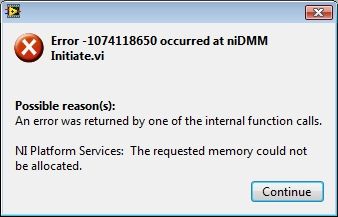
-error with the PXI-4070 107418650 same w/o autorange.
I have a PXI-1033, which includes a PXI-4070 module in slot 5. I use a version of the scanning of switch with DMM - Handshaking.vi but I changed to read a list of fixed scanning and I have replaced the meter of while loop with a fixed reading of 144 samples. After the execution of the present VI about 47 times I get this error:
I am NEITHER-DMM 3.0.4 OR-DAQmx LabView 2101SP1 9.3.0f2 and Vista Business 32-bit slot. I use 4 resistance wire and tried both auto and fixed the range with the same results. Before this loop the related single DMM functions is to read resistance readings 4 son and close the DMM. This seems to loop forever without any problem.
Dozens of times to restart a day gets old fast, any ideas?
-
PXI-8115 controller incompatible with the PXI-1050 chassis?
I replaced two XP based PXI controllers with two controllers, PXI-8115 with WIN7 installed on them. System #1 has combined PXI-1010 chassis and System #2 has a combo chassis PXI-1050 chassis. The two 8115 controllers work correctly when it is installed in the #1 system (chassis 1010) do not produce but no video output when it is installed in the #2 system (chassis 1050). I use the same monitor on both systems, as well as the same adapter DisplayPort to VGA supplied with controllers. This suggests some kind of incompatibility between the 8115 and the 1050, but I can't believe I'm the first to connect a 8115 a 1050. Everyone knows about this problem? Y at - it solution or workaround? Is there something I forgot?
Thank you
PMAC
OK, I found a solution but I still don't know why it is the solution.
Each controller had a "Bizlink" adapter DisplayPort to VGA bundled with it. Of course, I tried two adapters with the same results on both systems. I tried a "Startech" DP to VGA that is used elsewhere in the installation and the system worked well. Why a brand different adapter works is quite confusing.
For anyone else having this problem try Startech manufacturer DP2VGA.
PMAC
-
Application errors of the RT with the PXI-4461 with Labview real-time 9.0.1, DAQmx 9.0.2
HI -.
I recently converted a PXI time system real OS (PXI-1042 q chassis, controller PXI-8187, DAQ, PXI-4461, DAQ, PXI-6259). I can write and run DAQmx applications in real time with the 6259 very well. Whenever I try to write a labview RT app to use the 4461, however, it will fail. Note that I can use two cards through MAX I tried switching card slots, just in case it was a problem. Both cards worked with labview, the PXI chassis was before Windows.
Attached are pictures of the screw base demo I built to show the problem. Since I was a mistake (-200758) if I started from the raw strings, I tried to create a MAX task and use it. The task, but he complained of a buffer is too small. I explicitly put the buffer to work around this problem and still get the same error (-200608). I've also attached a screenshot of the software currently on the Max MAX RT PXI system is version 4.6.2 btw. (I installed the most/all this from DS1 Dev Suite 2010 version).
Please let me know if I hurt something installed, versions if 4461 just don't play nice with the new BT or RT software, or if something is wrong. Thank you.
Kregg
The first error you see is (details in the help-> error explain in LV)
-
How to trigger SMU - 6363 AI with the PXI-4142
Hello
SMU-1082
SMU-6363
SMU-4142
LabVIEW 2012 SP1
Hello
I'm trying to trigger action (SMU-6363) analog input with my SMU (SMU-4142). The API OR-DCPower has a VI called VI of Signal to export, that I could use to export the trigger signal in a specific line when 'Complete the event Source' comes up on my EMS.
The problem now is that i ' v tried several lines to transfer the signal to the SMU-6363, but unfortunately I still have an error of DAQmx. Has anyone tried similar before sync? Which internal lines I have to use to get this working? I'm just not producing a moment of tension at the time that the EMS (Single, Point). After SMU has defined the level it must send the trigger for SMU-6363 who would then measure the external signals constantly.
Thanks in advance!
-henkkaHello
I solved the problem of routing measure relaxation of SMU with Signal.vi export online PFI0 of SMU-6363 (SMU 3 channel). Then I started every other SMU channels (0:2) with this signal to trigger by using the configuration digital edge measure Trigger.vi (the VI input terminal is PFI0).
I configured the data acquisition sample clock to use the PFI0 as a source of the clock. With this method I am able to measure sinus 2 kHz generated with four channels EMS individually with my DAQ without no phase shift (0.1 degrees) between own EMS measurement and data acquisition.
Hope this helps anyone with the same kind of problem.
Best regards
-Henry
Maybe you are looking for
-
I had problems with the validity of the certificates for awhile on my laptop but I have the same version and settings on my desktop without any problem at all. All I get is a layout of the basic text by trying to connect to an https page, none of the
-
Touchpad on the Satellite P300 problem - 15 d
Hello world!! I bought a Satellite P300 - 15 d and I am experiencing some problems with the touchpad. I simply turn on the pc, and sometimes the touchpad doesn't work, sometimes not. I tried the FN + F9 key, but it just doesn't work. Even the touchpa
-
How to work with flags in scripts
Hi all I am trying to automate the process of evaluation of data for tiara using flags. So far, I can put the flags through script commands (chnflagset), but after that, I need go to the interactive mode to replace the data with NoValues flag (flags:
-
Updated graphical waveform constantly with digital I/o
I'm new to Labview and I try a digital waveforms graph to update in real time after the analysis of the data of a digital acquisition of data from input to output. Is this possible or real time update can only be done with graphics?
-
Dock keyboard W510 stuck in limbo?
Hello I plugged my dock + combo tablet to the charger before going to bed. In the morning, I noticed that the keyboard dock does not work anymore, the battery in the part of the Tablet has not been charged, and the little red light in the keyboard do