IVI range control and coercion
Hello
I'm working on an IviScope driver for a scanning module.
I have a question that keeps me busy.
Take, for example, the IVISCOPE_ATTR_VERTICAL_RANGE attribute.
My instrument has 8 fixed vertical lines. If the application selects a vertical range which is not exactly one of these fixed ranges, the pilot takes the rangetable and converts the value of the next range of fitting.
But if the application specifies a vertical range that is beyond the capabilities of the instrument (i.e. 50Vpp, where the instrument is only 20Vcc), test intervenes, saying "invalid value for the parameter or property. Even if in the InitWithOptions() option string I specify "RangeCheck = 0". With disabled test, I expect the driver to do any range of control, but only through force. Am I wrong? And the value might be forced to match maximum vertical range of the instrument?
Kind regards
gggggl
I'm sorry. You can skip the last answer. I update as follows:
Normally, if you call the InitWithOptions function with "RangeCheck = 0" in the chain of the option and the type of range table is IVI_VAL_RANGED, the set value will be set to the instrument without change and will produce a specific error of the instrument. If the type of the range is IVI_VAL_COERCED, the value will be converted even if you set RangeCheck to zero. In this case, you must make sure that the range table defines the constraint clearly rules. Otherwise, a runtime error c appears when you run the code.
If the attribute that you want to set is associated with a hidden attribute, you must check the interval methods too. It is more difficult to describe. You can edit the problem clearly to analyze it.
Tags: NI Hardware
Similar Questions
-
Location of the controls and indicators on the pallets
Is it possible to know the location of control and indicator on the pallets of a pre-designed vi?
THX
If you ask "Given control over the façade of an existing VI, how to find the range, in which it is originally found?"
There is no direct way.
If the controls have been customized, then there is no palette.
Ben
-
Discreet Integrator (control and Simulation Module) - LabVIEW 2015
Hey everybody,
I'm trying to drag the discreet Integrator on a block in 2015 of LabVIEW diagram. All other vi in the "range of discrete linear systems are draggable, but not the"discreet"Integrator." I noticed the same thing for the continuous Linear Systems Integrator. Anyone explain how to solve this problem?
Sincerely,
Lex
Lexicondi,
Unfortunately, these functions cannot be moved out of the loop control & Simulation. We support only discrete transfer, of State spaces and ZPK models function.
So, if you want the "discreet Integrator" outside of the SIM card, you have the following options:
one) to use the "discreet transfer function" as T /(z-1) (or any other type of discretization available in discreet Design continuous monitoring);
(b) you can develop your functions inside the control and the Simulation loop and then create a subsystem of her. The subsystem can move outside the SIM card also. Here, you can use any SIM function you want;
I hope that this should be sufficient for your application.
-
best way to control a large number of controls and indicators
IM building a façade with 46 orders and lights, all of type boolean.
the logic is control > send order series > receive > indicator set. I consider part of my façade (with 2 sets of control and indicator) and my block diagram.
I have to be able to control programmatically and through the front panel individually the status and indicators, or all at once (for example to reset the both). This should be done from the tab they are and another.
thought property nodes but still I would have 46 + 46 of them. same for local variables.
y at - there I way to refer to a control/indicator by its label (string) and change its value?
wouldn't be easier just to create two Boolean tables which maintain their Boolean value?
Please advise me on what options I have. I'm new to labview.
Thanks in advance.
-
I would like to combine several orders and LEDs on the front panel in a group in a way that allows me to do the whole group Visible or not.
I tried to use a Cluster, but it has a side effect that all elements must be inside the controls or indicators, but not mixed.
Is there any graphic element, like a panel that can contain other controls and indicators on the inside and make them Visible or not as a group regardless of whether they are commands or the LEDs?
Good suggestions on how to do this?
Thank you.
The tab control is still not my favorite, appearance but it's a way fast and effective to show and hide groups of controls and indicators.
-
loop control and simulation: sync settings
Hello
Is it possible to access times higher at 1 kHz source in synchronization settings, control and Simulation in a loop, without use of real-time targets? For example, using time cpu.
I use myDAQ OR data acquisition, and I need a 100 kHz synchronization source about.
Thank you very much.
Kind regards
Keshav
N ° when running on a PC of the class, you are working with a set of standard material (with its clock 1 kHz) and a non-deterministic BONE, and there is nothing you can do about it. That is why acquisition cards NOR are all smart devices with their own processors, memory, and clocks.
Mike...
-
Cursor at the same time serve as control and indicator
Hello world
Is it possible to create a custom control that serves as both a control and indicator? What I want is a slider vertical I can put a value with the help of the thumb or digital input, but I also want a horizontal line which would be about when the filling is (of which the value may come from feedback in my system). In my case, I want to set the voltage and see the actual voltage measured on the same cursor. Is this possible?
Thank you
Eric
-
Control and Simulation in a loop / while loop with TCP/IP reading / writing of synchronization
Hello, I have a problem with reading TCP/IP and written in two loops. The problem is NOT to get the two loops to read and write to and from the other. This has been accomplished. My problem is when I run control and the loop simulation on my laptop and the while on a RTOS remote on the controller on-Board of LabVIEW in a remote PXI chassis, the while loop the remote system running on four 4 times faster than the loop control and simulation on my laptop. In other words, for each iteration of the loop control and simulation on my laptop, there are 4 four iterations of the while loop on the remote system. I need to know how to get a degree of kinship (1:1) with these iterations of the loop. When I run a longer simulation in real time, say 10 seconds, the control and Simulation loop begins to slow, i.e. the simulation time slows down until it is no longer in real time and the "Late Finish"? Parameter is set to true and the LED lights and continues to stay lit. At this point, the system destabilizes due to what I believe is being well sampling rate too discreet and I have to end the simulation. How can I get a ratio of one to one between the loops and also to avoid slowing the loops causing destabilization?
To give an overview of my application, I implement a control system in a network, seen in "image2.png". This is achieved using my laptop as a subsystem 1. Reference signals are generated from the laptop and the error signal is produced. Control measures taken and the control signals are sent via TCP/IP to the remote system. Position feedback is returned, and the process repeats. My system has Core I7 Procs w / 3 GB of RAM, up to 1 GB/s speed via ethernet and LabVIEW 2011 installed with all necessary modules and networking tools. The attached VI Custom_Wireless_Controller works on my laptop. The remote system I'm working on that has the 7830 NI R Series with FPGA card. OTN runs on the PXI chassis with an enbedded controller that has networking capabilities of up to 100 MB/s via ethernet. I use the FPGA for the acquisition of data and apply control signals to my plant. The plant is the PCE twist connected to the FPGA through the cable of the ECP - RIO of NOR. Subsystem 2 is this side of the CNE. The FPGA collects position, he sends to the controller via the network, receives signals from the network drive and writes signals to the plant power amplifier that operates the plant. This process is repeated and the VI and is titled Custom_Wireless_Plant.
I appreciate the help really and look forward for her and for any question!
Well, the first step is to understand what you have set up right now. Your control and Simulation loop on the side of the controller is configured as 'Runga Kutta 4' and you have a loop timed on the other side. In addition, you have the primitives of TCP/IP on the control and the Simulation diagram and means he will perform (a message) on the size of each minor step, which in your case is 4.
So, you have two options:
1. replace the Solver side controller Runga Kutta 1 (this must synchronize loops)
2. hold RK 4, but create a Subvi around two primitives of TCP/IP and configure from the VI to run than the major (continuous) step-size. If you do it right, you should see a 'C' on the upper right part of the VI you have created.
Please let me know if what I said is not clear...
-
How do I click on a cell in a table control and display the value in a string?
What I want to do is click on a cell in a table control and have the value of the cell in an indicator of the chain. Cell that ever I click on, I wish that the value to be displayed in the indicator.
Thank you!
Use the property "Change Position".
-
control and simulation Module spring mass
I'm using Labview 2010, and tasked the simulation module (just 15 days before the date of expiry. trying to see if the program will work before I spend $4 K) and try to calculate the dynamic response of a spring index.
I was able to complete the program in the simulation section (I think). I now need to feed a sign of acceleration in the module which I have already captured at a sampling rate of 100 k/s.
Test technician said I should add 500 ms from zero to the front of the track to make sure that the system is stable before the trace of acceteration of power is in the simulation module. I have alreay done reading and adding zeros to the chain.
I can't feed the trace in the module control and simulation.
The engineer said he was able to do the math in MatLab and simulink (I think), because I have not used this program and we do not have a copy I am doing it in LabView.
In addition, I would add that this forum is blocked by my firewall to work.
If you need more information, I'll have to return to work and get it.
-
problem with tab structure control and event
Hello
My program has a tab control. In each tab, I have an event structure to control some events.
I encountered some problems. These are:
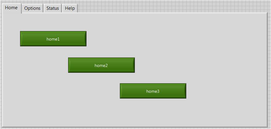
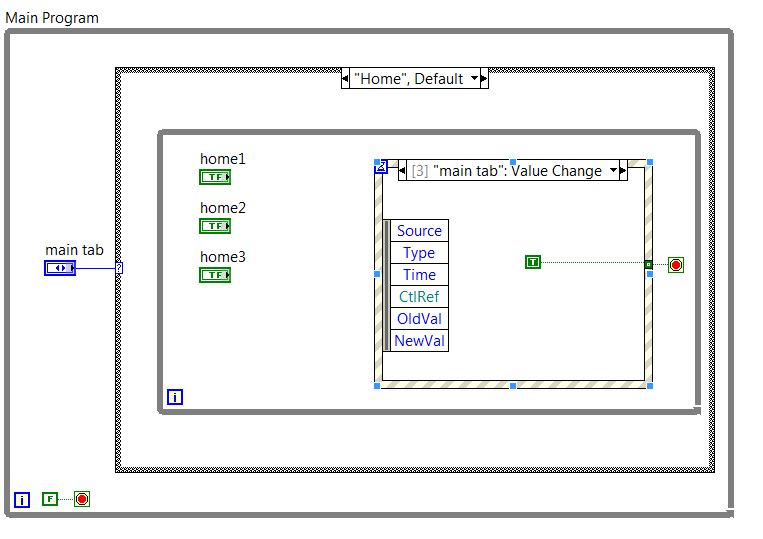
1. in each tab, I set tab as an event control, to altogether from the structure of the event as tab change (for example, the image below). My first problem is that when I change the tabs, in the arch depending on whether my program is entered in the next tab environment, happening at the event: change value to main tab! And gives bad result.
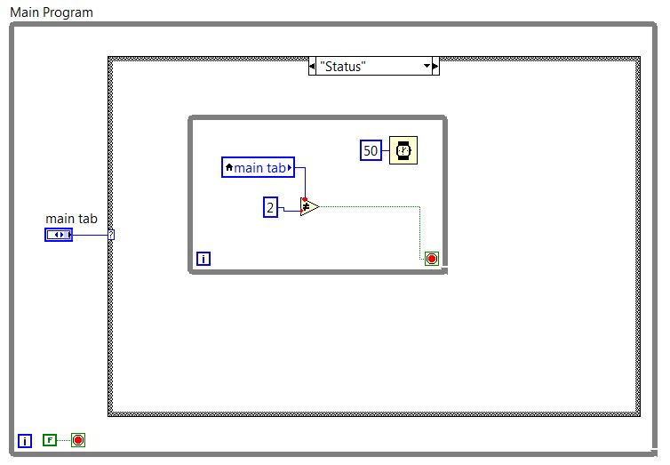
2 - I've scheduled two final tabs as below in the image. I had no routine in these two tabs. Simply, I want when I change the tab, it goes to the next case of the tab control. But when I run the program, it goes to something as busy after one or two changes tab and did not work properly.
Could someone help me please?
Thanks in advance
Baran
Rebecca wrote:
I want to have 4 tabs, each tab having 3 Boolean control.
If in each tab all Boolean control wins 1, a Subvi should be run.
I wrote this code with some time within each tab loop this case hase 3 for each Boolean control. The result is true.
But I think that if I write it with a structure of the event within each tab instead of 3 cases, the cpu load will be lower.
Is it not true?
Make a unique Structure of the event.
Add events for all controls (buttons, Boolean)
When the event is triggeredcheck for active tab control and decide what void / vi to run
It will work fine you
-
Problem control and Simulation
I worked in the module of control and simulation of NI Labview 2013 and created a VI as indicated in the attached file, but I don't understand the output of VI.
I applied a progressive input signal to device to transfer function = 1 /(s+1) and the desired output (exp (-t)) appears in green color (drawn by me in MSPaint) but it displays the output as one shown in red color.
As the inverse of 1 /(s+1) Laplace = exp (-t), the graph must be a value of 0.3678 at t = 1 and 0 to t--> infinite but the (red) output is exactly opposite.
Can someone explain please exit this is why it is like that?
Concerning
When you apply a step response, you must multiply your transfer function of 1/s to account for the progressive input signal before making the transformation from Laplace to get the correct result. In your case, the transformation gives: (1 - e ^ (-t))
There are many explanations of answers online, but here's onestep.
-
List of controls and indicators
Hello
Maybe I forgot something very simple.
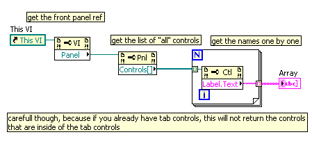
I am trying to clean my overloaded façade and edit it in different tabs. I have a lot of controls and indicators and property notes to make them visible or not. To make sure that I don't forget everything in the new façade, I would like to have a list of all the controls and indicators used in my application. A solution would be to create a new local go, select and write down the list complete, what is shown. Next would be to type all names in an excel sheet to a checklist that must be displayed where and when on the new front cover. Is there a better way, which is to export the list of Labview in a text file?
As... of the controls and indicators how?
With the help of the tabs is certainly a good idea to help organize your front panel, but if you use the tabs just so that you can have hundreds of controls and indicators on your front maybe there is something else you could do to improve your code similar to the use of several different types of controls (tables (, clusters, etc.).
But to directly answer your question, Yes, there is a way to get the list of all the controls on a panel like this:
hope this helps
-
How do I get the name of a duplicated or created control and add a reminder
Hi all
According to the number of entry points I need, I duplicate a digital or an input string to the DuplicateCtrl function. My question is, how do I get the name and id of the control that has been created, and how can I assign a callback to it? Alternatively, it would be better to create a fresh ctrl instead of duplicate?
Thanks in advance!
Hi TurboMetrologist,
Why are you trying to get the name of constant control? Remember that you cannot use this name to address control; control names are in fact simply the macros in the file associated with the UIR, include in other words, the preprocessed compiler code and everywhere where the names of PANEL_CONTROL replaces the digital value as parameters to functions (and therefore 'control' parameter is an int value and not a char *)
That's why NewCtrl () or DuplicateCtrl () functions return a control ID: this is the handle to the new object, the only way to handle it. You will need to store this handle in a nonvolatile memory so that you can access durng life program.
In addition, there are other ways to assign a meaning to a control to pass on the name of constant control. For example, you can use the callbackData parameter to differentiate the different copies of a control.
Let me explain with an example. You said that you need several entries (dynamically created that you don't know in advance how many of them use); a solution could be:
- Design a master copy of a control in the IUR Editor, where it is easy to customize; also assign a callback function, if it must be common to all copies of the control
- Assign a value to this control callbackData, programmatically for example SetCtrlAttribute (...,..., ATTR_CALLBACK_DATA, (void *) 1);
- Duplicate the control, and then assign a different callbackData
for (i = 2; I have< 5;="" i++)="">
handle = DuplicateCtrl (...);
SetCtrlAttribute (..., handle, ATTR_CALLBACK_DATA, (void *) I);
}
By operating this way, whenever the reminder of control is triggered by any control, it will receive the callbackData assigned, and you will be able to differentiate your code with a simple switch:
switch (callbackData (int)) {}
case 1: / / the master controls
break;
case 2: / / first dual control
break;
}
-
With regard to the values in controls and indicators
I entered a value in a control of channel 1. According to our requirements, this value is fixed. I entered the value and I closed the application and I opened the app, the next day. But there is no value I entered the control of the chain. The value must be perceived by the user. How can I do this in LabView? Thanks in advance best regards Christophe
After you enter the value you want, right-click on the control and select "... current value default data operation. Save the VI.
Maybe you are looking for
-
My company provides many educational resources via adobe flash essentially presentation Manager. Can I play flash in most circumstances under linux with firefox, just not these. Chrome, with exactly the same plugin dll, is able to read the presentati
-
Not satisfied with Lenovo warranty
I have a Lenovo Y530 bought new by Lenovo. Last week, I noticed several bright spots on my screen. I instantly thought of pixel problems. But later the technician by telephone reported a few broken LED? So he has arranged for me to send the laptop to
-
I did a clean install of vista on an old drive hard ide after the disk sata hard down - (oem version) now get "feature limited" because of the "unauthorized modification" had no problems for 3 years until this!
-
Hello I bought a new computer with Windows 8.1 Asus. I downloaded the driver for the 8600 and the printer to the troubleshooter. Both give the same result, they recognize the network but not the printer. I know that it recognizes the network becau
-
Cannot view Word doc, Excel, PDF out of any Web site
Having problems w/display nothing Word docs, excel, pdf etc out of sites - I downloaded windows 2003 and 2007, my laptop is a sony viao help more since I downloaded windows 7 - I Caan can't see my photos as I could before Original title: I can't see