Limitation of routing PCI-6602
I'm trying to use 4 counters to generate 4 signals, synchronized with external trigger (PFI, 38). If I use 0 to 3 meters, it fails to build a road linking the counter 0 internal output with the outbreak of departure of 1 meter. - like on the extract attached.
If I use any other counter (4 to 7) instead of counter 0, it works fine.
I couldn't find anything by banning the first NI Max table of routes of the devices configuration. It shows only ArmStart trigger connections, they are directly connected to the outputs internal counters if in the same half (0-3 or 4-7) and through trigger when the other bus.
Is there a way to establish a configuration like that without trying? Me read something wrong, is he full routing documentation somewhere?
Mx 9.3, MAX 5.0 data acquisition
An output meter task finished (at least 2 pulses) requires 2 counters on the 6602 (a counter to generate a signal square output) and the second counter to her door exactly when he finishes the last pulse. Consecutive meters are matched together to this effect (ctr4-ctr5, ctr0-ctr1, ctr2-ctr3, ctr6-ctr7). You run problems because ctr1 generates 2 impulses and therefore requires the use of ctr0 to achieve (if ctr0 is used for your other tasks it will not work).
New hardware STC3 as series X and CompactDAQ a paired internal counters (not accessible by the user), which makes the camera seem to be able to generate an output meter finished with a single meter.
Best regards
Tags: NI Hardware
Similar Questions
-
Support for triggers in PCI-6602 for counter input / output meter opearions
I'm sorry, it took a lot of time to test my application in a real NI PCI-6602 map. I am now convinced that put off against channels support start trigger, arms and relaxing break start trigger. But the input meter channels use pause trigger and trigger start of arms only.
I designed the app so that counter 0 is used as a channel of the meter and meter 1 serves as an output of the meter channel. The two channels are configured to use triggers to start of arms. Arms start triggers should come from a line of the RTSI. Using the terminal line 0 RTSI route connect API to arm the trigger for the start of the two channels. So when a pulse comes to line 0 in the RTSI two counter starts counting.
One last thing, I'd like to know, is how RTSI signals are generated? I know that RTSI is used for synchronization of several cards of NOR.
If there is only Board can we use the signal of the RTSI?
Can the hardware PCI 6602 itself generates all signals to the RTSI lines?
Thanks in advance.
Johnson
-
Photon counting using Photon unique cash Module and PCI-6602
Hi all
I am currently working on program couting of photons using a single (Excelitas) and PCI-6602 photon counting module connected to the BNC-2121.
I took a glance at other positions, but I still couldn't solve my problem (or, again, I'm not sure if yes or no, the problem is the specification of the material).
In the program, I'm generates a trigger to 1 MHz pulse using a trigger in a separate loop.
Other than that, I have loops of the producer-consumer model to get data and do a simple subtraction to calculate the number of photons in 1 microsecond.
According to the values connected to 'Input.BufSize' of buffer DAQmx and "Samples per channel" DAQmx calendar, I could change the loop number that the program has done its job correctly.
With the values, the program acquires photon 1 MHz with signls for 139 times.
After that, the program stops and the loopback number increases very quickly.
When I forcifully took stop the program, while the loop number increases very quickly, the program appears "error-200141".»
The error that says "data has been replaced before it can be read by the system." Mechanism of data transfer is interrupted, try to use DMA or USB in bulk. Otherwise, divide the input signal before taking the action. "even if the meter explicitly works in DMA mode by using the sample clock.
I wonder there is nothing that can solve my problem or even the only solution will buy a better Board of counters/timers.
Thank you all for reading this.
I will be very happy with any index

Kind regards
Myeongsu
Yes, the same thing happens on my system.
It does not happen with PCIe-6612.
I found more strange things:
When I start to reduce the frequency at a time given (800kHz) can fill the buffer, it will not start since the beginning of the buffer. He can go to the beginning of the buffer only at 100 kHz for my PC.
Options to fix:
(1) PCIe-6612. Seems to work. I tried streaming at 10 MHz, 5 min - fine.
(2) reduce the frequency of the pulse. If your laser supports 100 kHz, you're fine.
(3) put in place additional synchronous counter at 100 kHz. Basically, it's material average number of photons by 10 pulses.
(4) read 2 adjacent pulses each 1/50 kHz - then your data transfer will be 100 kHz and you will get the number of photons of this impulse of the 20 - th.
Programming issues:
(1) remove the display of the received picture, make only the processing of data and show results if you really need it.
(2) clock.vi sample sets the buffer size, if you specify the size of the buffer, do this after this vi.
(3) I deleted unnecessary "loop generation." He is running on the hardware and stops when you stop it - after reading the loop ends.
-
Continuous output of digital waveforms on PCI-6602
I use 6602 PCI to get a continuous 1 MHz square wave output of DIO1 ~ 32 sequentially controlled by LabVIEW. I Ctr0 to generate a clock 2 MHz and used Ctr0InternalOutput as a source of sample for DIO1 clock ~ 32. I have attached the code and the texture as follows.
The code works fine on PCIe-6251 and digital waveforms of 1 MHz is very stable.
But when I run on PCI-6602 I got an error-200077 (you asked for: sample clock; you can request: on-demand).
6602 PCI does support material timing? I found no information about this its specifications. If she can't, how can I avoid this problem and get what I want? Thank you!
Yi
Version: LabVIEW 8.2
hardware: PCI-6602
Hello
Have you looked at the specification for the 6602?
http://sine.NI.com/NIPs/CDs/view/p/lang/en/NID/1123
Click on "specifications". Scroll down to "digital i/o". Watch "Timing". It clearly says "software".
The DIO lines on this Board are not timed by the hardware. They are clocked by the software. The data sheet that explains very clearly. That's why you see the error clock sample - that the Council can't stand DIO clocked by the hardware.
The 6251 supports clocked by DIO material, so why your code works very well with this Council. You can do the generation of signals with a 6602.
Hope says.
d
-
Synchronization of the signal with PCI-6602
Hello
I need to generate three signals that must be synchronized.
To do this, I use a PCI-6602.
The first signal is used to trigger a device, the second signal is used to simulate the noise.
The third signal should wear the noise so that it starts before the trigger signal and stops shortly after the trigger signal.
The signals are then combined with an external logic circuit.
(To see what I mean, see the first PDF).
I use a fourth timer to synchronize all other clocks, but the three signals are beginning to run before starting the timer task. I have this evaluated using not to no and a oscilloscope.
The trigger and gate (first and last signal) are below 100 Hz, the noise signal is about 200 kHz.
At least the trigger and the door must be started synchronously, otherwise the waveform is not what we want. The noise signal didn't need to be synchronized.
I am sure I am missing just a little detail here, maybe you can show me what I missed.
Please check my screenshot of LabView to see what I've done here.
If you want more information about the VI, I can take apart a little and send it, too.
Try using start to the outputs of the 3 meter (see attached VI)
-
Hello!
My problem appeared when I tried to update my traditional NOR-DAQ legacy code to DAQmx.
I use 2 meter (meter 5 and 7 meter) on PCI-6602, to generate trains of pulses, as well as the lines of e/s digital port 0 (the form lines from 0 to 7). What I do in my request, it's that I'm starting to generate the pulse train on the output of 2 meters and after that I play with the State of digital lines.
Traditional, it was no problem to use the meters and digital lines at the same time, everything went perfectly, but in DAQmx, is not possible.
What's happening: I start generating train of pulses on the output of counters, no errors, but when I try to change the State of a line of digital port the generation of the pulse train is stopped. What happens when I start the task associated with the digital way.
My question is: is it possible to create a channel on digital lines without changing the channels created for meters?
Another thing that I managed to do with the panels 'Measurement and Automation Explorer' and Test for PCI-6602, is basically the same thing, I generate trains of pulses on the output of the 7 meter and try to start a job on the digital line, but I get an error:
"Error-200022 occurred in test Panel.
Possible reasons:
Measurements: Resource requested by this task has already been reserved by another task.
Device: Dev4
"Terminal: PFI8.On the contrary if I use the counter 0 or a counter 1 to generate trains of pulses I encounter the same problem.
What resources are used by 2 to 7 of the PCI-6602 card counters and the counters to 0 and 1 do not use?
Thanks in advance for any answer!
Ciprian
After doing some real tests on this device, I found that it is a normal behavior for the jury of 6602. This is because when you start a task digital all 32 lines are configured for digital i/o, so it replaces your meter operation. The article below the link explains a little more on this subject. You must start the digital task before the task of counter to use the features of both in your program.
2 meter and above will not work correctly when you perform digital i/o on NI 6601 or 6602
http://digital.NI.com/public.nsf/allkb/43F71527765EEC3886256E93006CD00C?OpenDocument
-
count digital events on a counter with pci-6602 with reminder on the CVI
Hello
I use a card PCI-6602 with CVI 8.5 and I need trig on the event.
On each pulse, I received, I need to do some actions like increasing a counter, send a message to Rs232 etc... I want to do no loop by checking that the value of the counter has changed. I would use a reminder to run this code only on the value of edge or a counter event.
My problem is that I don't know what function for this. Is it possible to get an event on a pci-6602?
Thank you
James
It's true. If a earlier without change detection and it works.
Thanks for your help.
-
Pulse width depends on the number of pulses (pci-6602)
Hello
I'm trying to generate samples done with pci-6602.
I use CO Pulse ticks + implicit options
External impulses is 1ms 1PPS pulse from the trimble GPS receiver
If I set the number of pulses = 1, then I had to pulse length (high ticks - 1) =
If I set the number of pulses > = 2 and low ticks > = 3, then I got pulse length = (high ticks)
If I set the number of pulses > = 2 and low ticks = 2, then I got last puls width = (high ticks - 1) and all other vegetables dry with length = (high ticks)
With a single generation pulse width pulse is (high ticks - 1)
Is there an option to configure the same pulse width for any number of pulses for a train over (N pulse)
screens to fix
-
Dear users of the forum,
I use a Counter/Timer OR PCI - 6602 for send TTL signals to another device in our laboratory. I send the signal every ~ 1-5 ms, but this time is not fixed (it depends on some other process that I do in my program of LabVIEW), so I can't use a continuous waveform.
So, I wrote a short test program to familiarize yourself with the PCI-6602 (see attachment).
If I send a pulse, it seems I can do this just about every 14 ms (at least this is calculated with the tick counts lag which is not very accurate; but to count the pulses with a meter gives almost as much time). So, it seems that the PCI-6602 has too long a response time for my application!
Can someone tell me if he made the same comment? Either I use the bad vi/treat the PCI-6602 in the bad sense? If Yes, what should I do to make my small test program and finally my main program faster?
I would be recognizing all the help and the comment!
partial81,
I have another idea for you to try. Starting the 6602 being the operation that takes the most time I wrote an example which uses a trigger to start to generate the impulse and puts in place the meter to retriggered. Basically whenever you issue a start trigger, the meter will generate a pulse. I then use a digital line on the 6602 to generate this trigger to start (I use PFI0 and Port0/$line0 which is actually the same line in the material). For the reenclenchee generation, wait until what is not useful, so I replaced it with a 1 ms wait.
Can you try this and see if it works better for you?
Dan
-
? the best way to test and calibrate a flow using a PCI-6602 meter?
I don't see. I want to take an E + H Promag 53 meter readings to a 6602 after a steady flow is reached. store about 4 values in registers a minute apart. compare to ESA and get the correction factor.
So I can read the pulses flow and/or charges.
in any case, I thought example would be much clearer and therefore I have modified your code shortly. have a look at.
-
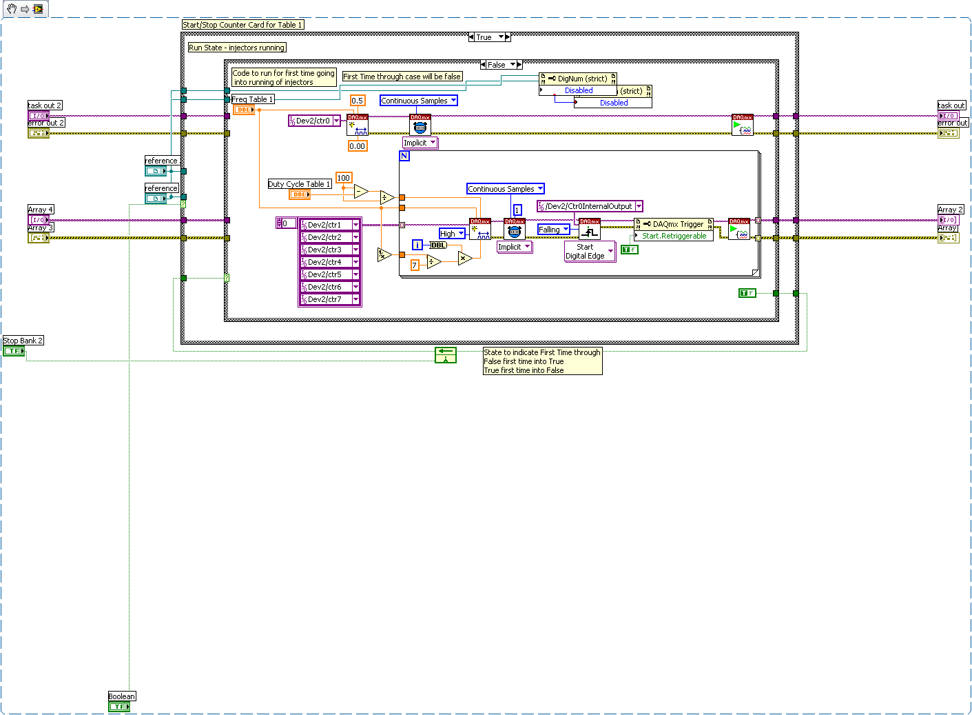
Hello
Currently, I use the code below to run counters to a frequency fixed/market factor. After the first counter triggers the rest of the counters, take turn of shooting using the terminal of initial delay on the creation of the channel vi. It works well and keeps them all to shoot at a time.
Now, I need to change the frequency/duty cycle once per second for 70 seconds (70 different points table) and repeat until I want to stop. I'm able to do it without any problem.
My problem is to put my initial delay each second based on my frequency to keep a nice ripple effect. In order to define the initial deadline, I have to stop the task. Is there another way to keep the evenly spaced counters (a beautiful ripple) depends on the frequency without stop the task?
I'm assuming that your need to stagger the injectors 'cooking' means that you are concerned by the timing of the active edges of the pulse. Whether rising asset or fall may not be particularly relevant if we can just make them very short duration.
1. I would like to begin by suggesting understand you the max freq reasonable you'll never need to host and then plan to stagger the firings through this same interval of time even when you operate at a slower rate that will simplify things considerably.
2 configure all of your counters in slaves to be redeclenchables (as you already are), but REMOVE the call to Timing.vi DAQmx they will all then be generators of redeclenchables pulse. Keep have triggered them by CTR0, the master clock.
3 set the slaves in terms of time of low / high time. Assuming the State of inactivity which is low (the default if I remember correctly), each 'initial period' equal to this unique 'small time' counters and define the minimum 'big time' can accommodate your system.
Note: unless the behavior has changed in more recent versions of DAQmx, the value of 'initial period' is used after 1st relaxation while the "small time" value is used for all of the following triggers. Don't ask * me * why, but NEITHER people have weighed in on this subject in the preliminary discussions, calling it of "expected behavior". EXPECTED by which is exactly what I wonder. I have yet to see a single comment saying: ' Yes, great, that's just how I * wanted * he behave. " IN ANY CASE...
4. start all your slave counters before you run the master.
5. the freq of the main counter can be changed on the fly without stopping and reprogramming it. All counters of the slave will continue to draw a single impulse per side assets of the master.
6 speculative idea, I haven't checked. You can * probably * update of low time / pairs high time the slave of counters on the fly as well. If so, this will allow you to broadcast the 'ripple' overall most of the available range during operation at low speed. It seems that your application can live with the possibility that these updates of the slave synchronization cannot occur in the same cycle of pulse master.
-Kevin P
-
Generate intervals of reactivation of precision using PCI-6602 software?
I use NEITHER-DAQmx in Visual Studio 2005 C++ under Windows XP.
I'm NOT using LabView.
I make an executable with high process priority and wish to have a real-time thread to wake up at time intervals of precision.
Currently, the time interval is 0.1 s (10 Hz).
I'd like the alarm clock to have low jitter, a few dozen microseconds or better.
Currently, I use a hack of previous work, generating a pulse with a period of 0.1 sec on a counter and wiring it in another counter to measure.
I use the DAQmxReadCounterU32() function with a value of 2 seconds of pause timeout and then reactivate my phone once the measurement is complete.
This "works" but the jitter is terrible: up to as much as 15 milliseconds for a freshly booted PC and 2 milliseconds after I enabled the features of multimedia timer.
What I want is just DAQmx function returns control to my request immediately after a break timer with optional output wiring of this impulse to timer.
So, how can I do this?
I came across a good solution.
I created a task to count the 10 Hz amounting to inheriting from the ctr edges 4.
This 10 Hz pulse is generated by another task on ctr 6 and is connected to the door of the ctr of 4.
But then, the trick is to synchronize the clock of installation using this same edge sampling:
RV = DAQmxCreateTask("",&taskHandle1);
RV = DAQmxCreateCICountEdgesChan (taskHandle1, "Dev2/ctr4","", DAQmx_Val_Rising, 0, DAQmx_Val_CountUp "");
RV = DAQmxSetCICountEdgesTerm (taskHandle1, "Dev2/ctr4","/ Dev2/PFI22" ');
RV = DAQmxCfgSampClkTiming (taskHandle1, "" / Dev2/Ctr6InternalOutput ", 100.0,")DAQmx_Val_Rising, DAQmx_Val_HWTimedSinglePoint, 1);
RV = DAQmxStartTask (taskHandle1);The thread at the time read real and simple loop indefinitely around the following statement which has a 2 second timeout:
RV = DAQmxReadCounterScalarU32 (taskHandle1, 2.0, data, NULL);
This reading will return immediately after a new rising occurs and then I have another task that switches to a digital output line that allows me to determine latency between the front and my code is activated.
I recorded and plotted a few minutes delay data and see my latency time varies between 50 and 110 microseconds, which I think is as good I'll get here.
See attachment data field.
The other good news about this method is that is uses less than 1% of the time processor.
-
200474 error occurred at Assistant(pci-6602 to scb68) DAQ
I had to work on another PC. Is there something wrong with the drive or the PC itself?
What is the purpose of the DAQ Assistant? On behalf of the device changed when moving to PC? You run the DAQ Assistant?
Kind regards
Glenn
Technical sales engineer
National Instruments
-
Genral how do synchronized encoders work with a PCI-6602
Well, here is the work routine for syncronous data two encoders, and it seems to work very well.
I have this working with my two 2000 encoders of CPR, let's see how it works when I get the CPR 500 000 encoders later.
The three major problems that caused it does not work have been:
(1) argument to the task of createCOpulsechanfreq must be between 0 and 1 of the cycle Theduty. I had ' 50.0 ' before, it works when it is "0.5".
(2) the time base sample that I used (ctr7) necessary must be started before one of my two angle encoder tasks have been created
(3) the string "dev/PFI8" should be replaced by ' / dev/PFI8 ". I don't really understand why, but it was what seemed to fix it.
If this question has been answered... Now I have a different problem when playing 8 values PWM both with the Semiperiodcounter, which I'll post in a new a different thread.
Thank you!
"' Working code here
Public Sub Aquireposition(samples As Long, data0() As Double, data1() As Double)
Protected BaseTaskHandle as long
Dim encoder0TaskHandle As Long
Dim encoder1TaskHandle As Long
Dim TaskIsRunning As Boolean
Dim ReadCount as long
Dim strCounterString As StringOn Error GoTo ErrorHandler
DAQmxErrChk DAQmxCreateTask ("base", BaseTaskHandle)
DAQmxErrChk DAQmxCreateCOPulseChanFreq(BaseTaskHandle, "/Dev1/ctr7", "base", DAQmx_Val_FrequencyUnits2_Hz, DAQmx_Val_Level1_Low, 0#, 200#, 0.5)
"Specify the continuous time
DAQmxErrChk DAQmxCfgImplicitTiming(BaseTaskHandle, DAQmx_Val_AcquisitionType_ContSamps, 200)
"Startup DAQmx code."
DAQmxErrChk DAQmxStartTask (BaseTaskHandle)
"DAQmx Configure Code
DAQmxErrChk DAQmxCreateTask ("encoder", encoder0TaskHandle)
TaskIsRunning = True
DAQmxErrChk DAQmxCreateCIAngEncoderChan(encoder0TaskHandle, "/Dev1/ctr0", "", DAQmx_Val_EncoderType2_X4, 0, 0#, DAQmx_Val_EncoderZIndexPhase1_AHighBHigh, DAQmx_Val_AngleUnits2_Degrees, 500, 0#, "")
DAQmxErrChk DAQmxCfgSampClkTiming(encoder0TaskHandle, "/Dev1/PFI8", 1, DAQmx_Val_Rising, DAQmx_Val_AcquisitionType_FiniteSamps, samples)
"second encoder.
DAQmxErrChk DAQmxCreateTask ("encoder1", encoder1TaskHandle)
TaskIsRunning = True
DAQmxErrChk DAQmxCreateCIAngEncoderChan(encoder1TaskHandle, "/Dev1/ctr1", "", DAQmx_Val_EncoderType2_X4, 0, 0#, DAQmx_Val_EncoderZIndexPhase1_AHighBHigh, DAQmx_Val_AngleUnits2_Degrees, 500, 0#, "")
DAQmxErrChk DAQmxCfgSampClkTiming(encoder1TaskHandle, "/Dev1/PFI8", 1, DAQmx_Val_Rising, DAQmx_Val_AcquisitionType_FiniteSamps, samples)"Startup DAQmx code."
DAQmxErrChk DAQmxStartTask (encoder0TaskHandle)
DAQmxErrChk DAQmxStartTask (encoder1TaskHandle)
"DAQmx Code reading
DAQmxErrChk DAQmxReadCounterF64 (encoder0TaskHandle-1, 0.05 * samples, data0 (0), samples, ReadCount, ByVal 0 &)
DAQmxErrChk DAQmxReadCounterF64 (encoder1TaskHandle-1, 0.05 * samples, data1 (0), samples, ReadCount, ByVal 0 &)
"Everything is done! StopTask
' DAQmxErrChk DAQmxStopTask (TaskHandle)
"Work stoppage is not necessary because the clear task also stops task"
DAQmxErrChk DAQmxClearTask (encoder0TaskHandle)
DAQmxErrChk DAQmxClearTask (encoder1TaskHandle)
DAQmxErrChk DAQmxClearTask (BaseTaskHandle)Exit Sub
ErrorHandler:
' MsgBox "error:" & Err.Number & ""& Err.Description, "Error".
' mlngPWM_ErrorCount (lngChannel) = (lngChannel) + 1 mlngPWM_ErrorCount
"MainForm.PWMErrorCount =" errors ("& lngChannel &"): "" & mlngPWM_ErrorCount (lngChannel)
Next summaryEnd Sub
-
multi meter PCI-6602 daqmx semi period measurement
Hi all, currently I am working on 20 channels PWM. I have a problem on my labview code. Would anyone give some advice on my vi? I packed for 2 channels labview code, for now. I do measure period semi. I want to measure the cycle frequency and the duty of the PWM signals. But when I run it, it has error. Please give some tips where I did wrong on my vi. Thanks, Johnny
Marconi salvation,
This error you are getting is a buffer overflow error and is probably due to the value that you used as an input for "number of samples" on the reading DAQmx VI. You set it to 4 but according to how fast the PWM you read is, you can acquire values in the buffer on board much faster that you collect with the reading DAQmx VI. Then when you call the DAQmx Read VI, who reads from a pointer to read the data you plan to read the buffer has already been replaced. One way to get around this is to increase the number of samples to read whenever you call the DAQmx Read VI. I tried your VI and managed to do work with a slight change to the trigger start (using the PFI0 instead of the time base of 20 MHz) and added a loop condition to stop making a buffer overflow error as well. Take a look and see if that helps. In addition, why you fire off the coast of the time base of 20 MHz? is there a particular reason? It is essentially similar to using no trigger starting since you should get the first front of this almost immediately after the start DAQmx VI is called. I'm just curious, since using this trigger from the beginning has not actually worked for me (although I look into why).
Chris W
Maybe you are looking for
-
My computer knew some problems turning on and I took it to the genius bar. They went through my MacBook as there are of course many causes possible so I went to pick up another day, when they were performed. I have just return and everything works we
-
El Capitan is always full of problems?
Looks like El Capitan's full of problems still? I want to improve, but I'm quite scared!
-
Hello, I have problems with my wireless connection. I have a Y-560 I bought about three months ago. I just got a new Wireless-N router able and when I set up to only pass N-mode, my wireless no longer works. Mode mixed (B/G/N) or N/G mixed, it works.
-
Reading an XML created previously by LabView
Hello world My problem is, as the title says, I need to read data from an XML file, if the file does not exist, creates it LabView. So far, it's working. After the creation, when I start the subroutine and want to read the data from the XML file, it
-
HP LaserJet P1006 does not print
From my HP LaserJet P1006 to connect to my wireless router's USB port. When I tried to print my computer went on the Net to download the printer driver. I tried to print again. I have received the print dialog box, choose the printer that was connect