Logic Node 9.1.8
Hi-
9.1.8 logic node does not appear to have installed on my system. Where can I get?
Thanks-DN
It is no longer available for purchase
Tags: Professional Applications
Similar Questions
-
Node of automation is much more difficult to 'uncheck' than to 'create '.
I use logical X about 5 months now, and I felt a fairly frustrating relationship with interaction of automation. When I load automation, 'creation' of a knot of automation is simple... 1. click anywhere along the yellow line creates a node that is precisely where I clicked. However, "popping/unclicking/destroy" this same node takes anywhere from 3 to 6 clicks to work. I would love to be able to uncheck these nodes with the same exact ease with which I am able to create. No relief in this case would be great! Thank you
Double click on the node to remove it... as simple as when it was created... Click to create, double-click Delete.

-
LabVIEW FPGA: Integration node clock wrong
Hello
I'm having some difficulties to understand how the clock is part of the node IP for LabVIEW FPGA and was hoping to get some advice.
What I try to do is to set up a digital logic circuit with a MUX feeding a parallel 8-bit shift register. I created the schema for this Xilinx ISE 12.4, put in place and can't seem to import the HDL code into an intellectual property node. When I run the VI, I am able to choose between the two entries for the MUX, load the output in the shift register, clearly the shift register and activate the CE.
My problem is that when I switch to the entrance of THIS, he should start 1 sec shift (Boolean true, SCR, High, what-have-you) in the registry once each clock period. Unfortunately, it instantly makes all 8 bits 1 s. I suspect it's a question of clock and here are some of the things I've tried:
-Specify the input clock while going through the process of configuring IP nodes.
-Adding an FPGA clock Constant as the timed loop.
-Remove the timed loop and just specifying the clock input (I'm not able to run the VI that I get an error that calls for a timed loop)
-Do not specify the clock to enter the Configuration of the IP node and wiring of the FPGA clock Constant to the clock input (I can't because the entry is generated as a Boolean).
-Remove an earlier version of the EC who had two entries up to a door and at ISE.
-Specify the CE in the process Configuration of the IP nodes.
-Not specify this in the process of setting up nodes IP and wiring it sperately.
-Various reconfigurations of the same thing that I don't remember.
I think I'm doing something wrong with the clock, and that's the problem I have. Previously, when I asked questions to the Board of Directors on the importation of ISE code in LabVIEW FPGA, a clock signal is not necessary and they advised me to just use a timed loop. Now, I need to use it but am unable to find an explanation online, as it is a node of intellectual property.
Any advice would be greatly appreciated, I'm working on a project that will require an understanding how to operate clocks the crux of intellectual property.
Thanks in advance,
Yusif Nurizade
P.S. I have attached my schematic ISE and the LabVIEW project with one of the incarnations of the VI. The site allow me to add as an attachment .vhd file, but if it would help I could just paste the body of the code VDHL so just let me know.
Hello Françoise,.
I spoke to the engineer OR this topic and it seems that it was sufficient to verify that your code works, by putting a wait function of 500 ms on the while loop to check that the registers responsible and clear. I'm glad that it worked very well!
-
LabVIEW FPGA CLIP node compilation error
Hello NO,.
I work on an application for my Single-Board RIO (sbRIO-9601) and faced with a compile error when I try to compile my FPGA personality via the ELEMENT node. I have two .vhd files that I declare in my .xml file and all at this point works great. I add the IP-level component to my project and then drag it to the VI I created under my FPGA.
Within the FPGA personality, I essentially have to add some constants on the indicators and entries CLIP to my CLIP out and attempt to save/compile. With this simple configuration, I met a compilation error (ERROR: MapLib:820 - symbol LUT4... see report filling for details on which signals were cut). If I go back to my VI and delete indicators on the output (making the output pin of the CLIP connected to nothing), compiles fine.
I've included screenshots, VHDL and LV project files. What could be causing an indicator of the output of my VI to force compilation errors?
Otherwise that it is attached to the output ELEMENT, a successful compilation...
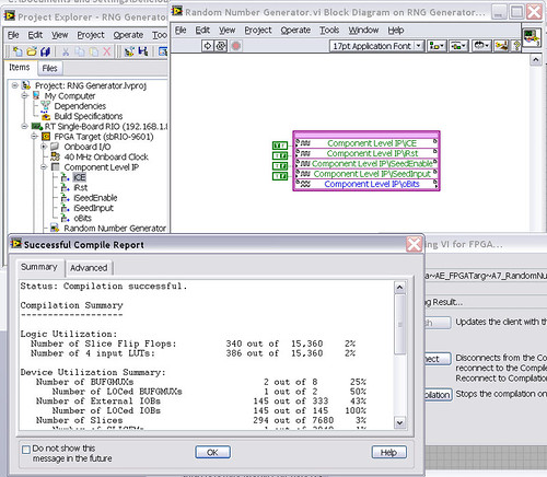
After that the output indicator comes with CLIP, compilation to fail...

NEITHER sbRIO-9601
LabVIEW 8.6.0
LabVIEW FPGA
Windows XP (32-bit, English)
No conflicting background process (not Google desktop, etc.).Usually a "trimming" error gives to think that there are a few missing IP. Often, a CLIP source file is missing or the path specified in the XML file is incorrect.
In your case I believe that there is an error in the XML declaration:
1.0
RandomNumberGenerator
urng_n11213_w36dp_t4_p89.vhd
fifo2.vhd
This indicates LV FPGA to expect a higher level entity called "RandomNumberGenerator" defined in one of two VHDL files. However, I couldn't see this entity in one of two files. If urng_n11213_w36dp_t4_p89 is the top-level entity, edit the XML to instead set the HDLName tag as follows:
urng_n11213_w36dp_t4_p89 Also - in your XML, you set the 'oBits' music VIDEO for output as a U32, however the VHDL port is defined as a vector of bits 89:
oBits: out std_logic_vector (89-1 downto 0)
These definitions must match and the maximum size of the vector CLIP IO is 32, so you have to break your oBits in three exits U32 output. I have added the ports and changed your logic of assignment as follows:
oBits1(31 downto 0)<= srcs(31="" downto="">
oBits2(31 downto 0)<= srcs(63="" downto="">
oBits3(31 downto 0)<= "0000000"="" &="" srcs(88="" downto="">Both of these changes resulted in a successful compilation.
Note: The only compiler errors when you add the flag because otherwise your CUTTING code is optimized design. If the IP is instantiated in a design, but nothing is connected to its output, it consumes all logic? Most of the time the FPGA compiler is smart enough to get it out.
-
I'm having a problem understanding of logic in the attached vi. It is a part of a larger system, and I put the normal entries to the values provided by the other vi to test this vi. I do not understand is the value of the wire labeled "Output Increment" inside the logic of 'Run-Off' when the increment evaluates during the only browsing the vi (works in the same way in the application of the system). At this point in the performance, the output of the increment is 56 when I was expecting a value of 1. (The logic of "run on" above is similarly when ' RunOn/runoff' boolean is set to True.) Also, why, when I probe wire node 'Run Off Counter Out', is the probe name "Run Off Counter In"? I'm relatively new to LabView programming and would appreciate greatly any help.
Thank you
Mel
Thanks for the help. I figured it was something elemental, but I do not want to check the wiring, because the thread seems to go to the desired terminal. All in all, a stupid mistake.
smercurio_fc wrote:
About the code: it seems awfully complicated. What exactly are you trying to do? FYI: ANDing a Boolean with a real is redundant. It's like the multiplication of a number by 1.
____________________________
Understand ablout the true. The real replaced a parameter that is defined in a different vi and referenced here. I replaced it so I could join only the a vi. This vi is part of a much larger application that, under certain conditions, needs to use a time-out "run on" and in other conditions delay "Run Off". The magnitude of the two delays is configurable by the user.
Once again, thank you for the help. I'll redouble my efforts to find this kind of error before you post.
Problem solved.
Mel
-
MathScript node: an error internal mathscript: 64-bit LabVIEW 2009
Hi people.
I have an installation now LabVIEW 2009 9.03f, Vision and Advanced Signal Processing Toolkit, all 64-bit versions on a new computer, so that I can convert a code from 32 to 64-bit.
I tell myself that I will address the errors one by one and this is the first. I have a VI with mathscript node and the VI, who instructed and ran very well in the 32-bit environment, is now broken and giving the error "mathscript node: a mathscript internal error." My main concern - is mathscript unsupported in LabVIEW 64-bit right now?
I enclose the VI. Any ideas are appreciated. I need to get this working.
In addition, NEITHER is there a special forum of 64-bit we should publish in the future, or create to post on?
Sincerely,
Don
LabVIEW MathScript is a language based on text that you can use to write scripts and functions. You can process the scripts using LabVIEW MathScript in the Window of LabVIEW MathScript or a MathScript node. When you create a LabVIEW MathScript, you use data types supported.
The MathScript syntax is intuitive and logical syntax essentially based on the standard mathematical and computer programming terms, mandate of widespread and common use truncation or descriptive abbreviations and concatenations of standardized terms. The Window of LabVIEW MathScript and MathScript nodes are able to process files that you create using the MathScript current syntax and, for backward compatibility, files that you created using legacy MathScript syntaxes. The Window of LabVIEW MathScript and nodes MathScript can also process some of your files using other textual syntaxes, such as files that you created by using the MATLAB® software. Because the MathScript RT Module engine is used to treat the scripts in the Window of LabVIEW MathScript and MathScript node, and the MathScript RT Module engine can't stand any of the syntaxes, not all existing text scripts are supported.
(64-bit LabVIEW) LabVIEW MathScript is not supported in LabVIEW (64-bit).
-
The value of property to an array element node: How does it work?
As I tried in vain to understand my shipment of samples recent misconception (here), I came across a behavior that I'm not sure I understand.
Here it goes:
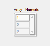
Move a table of numeric values to the FP show. a few items. The easiest way is to take a 'table - Numeric (Silver)' pre-formed object with 3 items listed.
Now, right-click on the top element and select: create > property node > value
Change this to write about the BD and to connect a constant, say 1. Run the VI, you get this:
===>
So far so good.
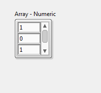
Now do the same for the THIRD item and wire a different constant to the AP, say 3. Rerun the VI, you get this:
===>
All right...
I mean, it is not already made a lot of sense, but wait what will happen...
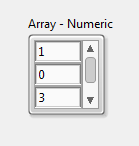
Now remove the first NP and run VI again:
===>
Quite logical, right? ... not!
At least * I * can't make sense of it and it smells like a bug to me... or a weird feature.
Tested in LV 2013 SP1 (62 + 2 bits) on Windows 7 64 bit.
You create a shortcut to write to the ArrElem.Value property. The property ArrayElement to a table is a little funky, it is the last element that was active. With only a single PN on your comics in writing a value, click in the central element of the array, and then run the VI, repeat for the other elements.
-
Pass the value to the node e/s in FPGA.vi of Host.vi FPGA
How to place a different value to the FPGA.vi of I/o of the Host.vi node? In the FPGA, I made the I/O node 'control', but when I try to use the read/write command in my host none of the e/s appear in the menu dropdown. All my booleansare it. See screen capture.
Thank you...
That's exactly right. Don't forget, when you compile an FPGA VI you essentially create the material and directly attributing to IO advanced logic. You can use a case to transport the data to the channels of e/s suitable for the test that you use if you have a series of assignments of specific channels for each test.
-
Brushing up on basic text read someone elses formula node
I need to refresh my knowledge of text-based. I read someone elses code and it contains the node of this formula. Any help to understand the logic inside or to see an equivalent LabVIEW would be very much appreciated.
What nice looking G code.

-
Nodes property RT for Typedefs
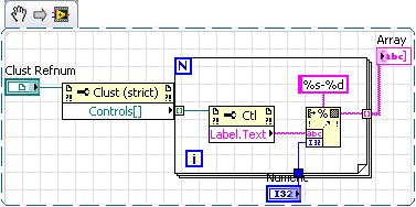
I add a new feature to an application of the CR for which I would like to maintain scalability and flexibility by using a type of cluster definition. The cluster will represent the channels to use for a particular modular Subvi. I will reference this cluster in several places, and there's a chance I might need to add new items in the future, that's why I want to use a type definition (to apply the update in the world of the location of a file).
I also need to be able to return the list of items in the cluster. Normally, I would do by accessing the Controls [] property, then through each control for the Label.Text for individual element names. Unfortunately, I can't access these properties on an RT target. [Well, I can if I run in the development environment, but not when compiled into an executable file] I understand that some nodes of property are not available on the objectives of the RT, but it is not clear to me who is and is not. For example, I often connect via remote façade panels, and I know that I can use the Visible? and nodes of property mode disabled on front panel controls (reading and writing) without problem, even if the position of NOR, it's that the front does not exist on the objectives of the RT. Why can I use these properties, but not as simple as controls [] and Label.Text?
Also, anyone who has run in a similar situation and has found a way around it? It's a way to enjoy the benefits of the type definitions (which is globally set to day) for groups of channels on an RT target?
TurboPhil wrote:
Thanks for the explanation, Justin. It makes sense to instantiating a connection of façade (via the development environment) the impact to the target RT read some nodes of property. Or, at least I can see the logic behind it. I still think it would be nice if some properties might be available for the target of RT running without a connection to the front panel, provided that the reading of these properties will not affect determinism of the system...
As for your suggestion of table, yes I totally agree with the concept. Except that - at least to my knowledge, it is not a good way to pre-populate the table in all instances. In other words, I want to have a list of predefined strings, defined as a type definition so that I can call from several screws and if I need to add / remove from the list at any time, I just need to change the definition of a type. Using, say, an array of strings, the best I can do is to use a control and change the default value. But would not be spread in all instances of control throughout the project.
In general, I use an enum typedef to define lists of channel, and I have a little Subvi to go through each element of the enum (since I can not access the property names point []) to return a list of the elements in the chain. In this case, however, I wanted to have a little more flexibility: I want a typedef cluster whose elements are channel types and the entries of these elements specify the names of channel. Specifically, I work on a scalable CAN interface Subvi, which must be able to communicate with devices on several different manufacturers; for each device, I have a list of types of conventional channel which I will use for communication (set point, feedback, temperature - to be represented by elemnt cluster names), but each manufacturer has a different channel name ('SRA_Desired_Pos', 'SRA_Actual_Pos', 'SRA_Internal_Temp', etc - will be reflected in the value of the element of cluster chain) for each type.
I was wondering if anyone out there has run into this kind of situation and find a clever way around it.
"Well, that's a horse of a different color!"
Just parse the descriptor type of the enum.
Ben
-
Active cursor (property node). You will need to obtain a number of active cursor.
Hello world
I have searched for this answer for a while and found no one. So, let me describe my problem:
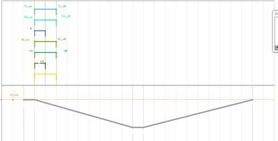
I have a XY Chart with 10 sliders on a FP. On the comic, there is an event-driven state machine.
I want to use a node of ActCrsr materials for a number of active when cursor occurse event (event of slider type for example). Unfortunately, LabVIEW gives me only 2 numbers of cursor and I don't see any logic behind it!
Why do I need? Imagine, when you take a cursor, the graph to which he belongs to type of assets (the line is thick and the name appears and so on). My program visualizes graphic adjustments of pulses.
Thank you very much in advance!
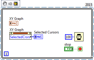
Hello
You must use the property "SelectedCrsrs". Try the example below.
-
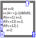
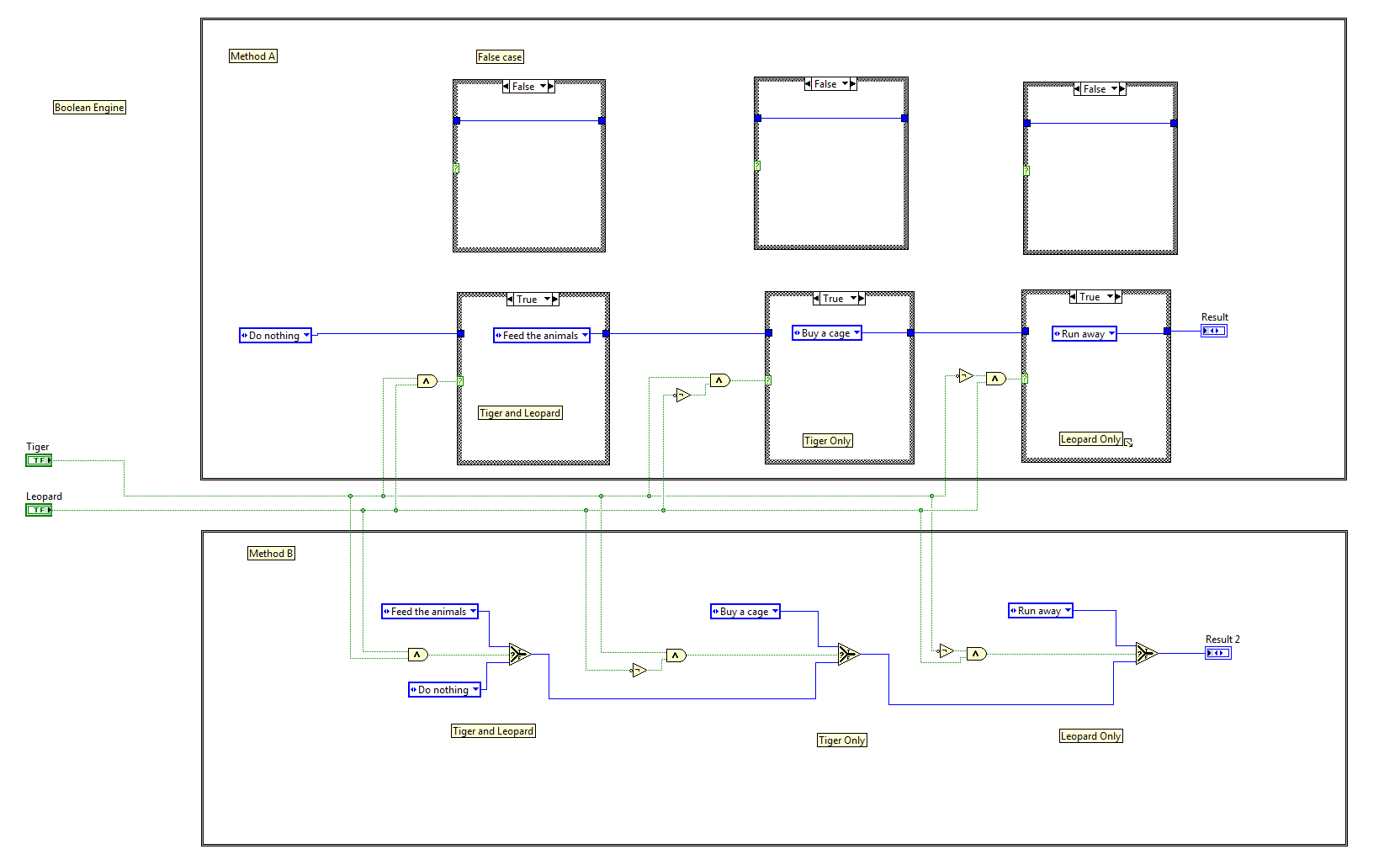
Hello! Recently, at work, I was responsible for creating the code that returns something on two Boolean State. Something like: If Boolean has and Boolean B, return if Boolean is and B no Boolean etc something else.
At first I thought that the best way to do it would be a formula node with the return value is passed through a bunch of if else statements. Then I discovered that Booleans are not supported in notes formulas and forms knots are designed for writing formulas, and not for current programming, that makes sense.
I came with two ways to do it, but I felt that they were both quite stocky and they suck if I had more than 2 Boolean values my logic on the basis. Here is the code with the two different methods.
I feel like this is an operation that would be much better to do it in an if else statement in code and I would like to know if there is a better way to do this in LabVIEW.
Typical in LabVIEW is to combine Boolean both in a table, then use of the boolean to number table. This will give you a value between 0 and 3 (included). You can use a single case statement, or you can create a table of values of output desired and use it as an index in the table, or if there is a direct mapping of the enum, you can simply convert that number to the enumeration type.
-
OK the property button (LV7.1) cluster node
Hi people,
I already found a solution to my problem, but I was wondering if someone could put a logic to it. I created a group of Boolean values with buttons OK because I wanted to use custom text labels, etc. When I unbundle the cluster, I get the Boolean desired. However, when I created a property node, the value was the variant - makes no sense to me. If I wire the property node to a conversion of the VI Variant (with the Boolean type), the output of the property node suddenly becomes Boolean and stays that way when I remove the conversion VI - makes even less sense.
Why OK buttons are somewhat different from other Boolean when used in a cluster?
The fix that I went was to create a bunch of LEDs square with text, turned in the controls and then put them in a cluster.
Michael Tracy
Synergy microwave
The property node was a variant because the 'OK' button is a type of lock. You shouldn't read/write locking type buttons programmatically, because a race condition is inevitable. Your question didn't concern the cluster.
-
Node property accessor vs LVOOP
I spent my CLD and exploring the world of LVOOP. I am a mechanical engineer with about 1.5 years of experience in LabVIEW, so I still have a ton to learn.
While browsing through the LVOOP, I ran across things that I can't reconcile.
When is the right time to create an accessor for a property of a class method and what is the right time just use a node property to get or set a node of class?
Data class must have all children data parent instantiated inside more his own? Or does just have its own data? (that is, if the parent has child Name and Value, should he Name, Value and amount or quantity?)
Can anyone provide an example of Composition as a class relationship? I understand the LVOOP class training that the Composition is a "has - a" relationship, but I'm still not sure what this means in reality in the real world.
Any help is appreciated. Thank you

Welcome to the object-oriented approach.
When is the right time to create an accessor for a property of a class method and what is the right time just use a node property to get or set a node of class?
I used to always create accessors and it is advisable to do so. Technically if the accessor is private (which means no VI outside the class can call) and you don't need to do any checking of range or any other logic on a read or a write and your class is not to have children, then you might get away with just using a ungroup by name (using a property node requires creating an accessor - the property node is just syntax to call the accessor).
An accessor allows you to:
- the scope of access (i.e. which is able to access these data, data of class being always private in LabVIEW)
- error checking or conversion to centralize code
- protect code against changes how store you a value (as long as you can write an accessor which returns a value in the specified format, the way the value is stored internally to the class will not affect the rest of the application)
- have a single point to debug
Data class must have all children data parent instantiated inside more his own? Or does just have its own data? (that is, if the parent has child Name and Value, should he Name, Value and amount or quantity?)
Not if you use accessors to get data from parents. Because the child inherits all methods of parents, he can call the parents of the accessor methods. Recreate the fields Name and Value of the child class would be exactly what OO tries to avoid duplicate work.
Can anyone provide an example of Composition as a class relationship? I understand the LVOOP class training that the Composition is a "has - a" relationship, but I'm still not sure what this means in reality in the real world.
Of course, take the job template DAQmx for example. A task class contains information of calendar and 'a' one or more channels in. Each channel can be it's own class that represents the type of measure and scale for this specific channel information. Given that the task class contains an array of classes of channels that have no use outside the context of a task, then you have a composition relationship.
Hope this helps clear things
Simon
-
How to implement logical equations such as LabView?
Hello
I have this bit logical test I need to implement a Labview code.
Can I use formula node or anything similar to this already in Labview?
"((var & (1
a certain number of bits. 0 is the least significant bit.
Thank you
Do

Spin and not equal to zero

Maybe you are looking for
-
The BigFun.be site video requires a plugin. Which plugin? I tried to download the video player of Microsoft for Firefox 1.0.0.8 and it don't take or show up in plugins.
-
DVD drive for HP Envy running Windows 8
I get an error regarding a possible corruption with the driver for my DVD drive on my HP Envy (Windows 8) factory installed. When I try to update the driver through the Device Manager, it says the best driver currently installed. Unistal does not h
-
I always copied files on diskettes. I am now trying to learn how to record on CD and transfer or copy files from diskettes to a cd. my computer has a cd player, but I'm not if it is equipped with a cd recorder? I have only had it a few months and n
-
My phone is Sony Xperia Z3.After the latest version of Android 5.1.1 gyroscope works do not. But the service menu * #* #7378423 #* #* work. This shows that there is a problem of software with the latest version 5.1.1 Lollipop. I hope to eliminate it.
-
Upgrade POWER Inspiron 3847-10000bk
I intend to upgrade 300w PSU from my desktop 3847 to an EVGA 650w PSU. The latter is slightly longer, but I'm sure I can get to fit. It also comes with many connectors, including the 24 pins and connectors 4 pin on my mb. I ran this by Dell technic