Matrix relay
Hello everyone
I am completely new to Labview. My problem is that I'm trying to run a project conceived on relay matrix. When I try to run it, I get a lot of mistakes even after you download all the required files. He asks the files as in the 1st photo. But even after their download, I get errors and warnings as 3rd pic. I tried to download the whole project, but I'm unable to do so. I don't know where I made the mistake. Could help me with this problem please. Thanking you in advance
Hi Alain,
the project sotres to explore the paths of the screw and other files (dll, for example) that you use in the project. delete or rename the files on disk causes facing them questions. See this link:
http://zone.NI.com/reference/en-XX/help/371361K-01/lvconcepts/resolving_project_conflicts/
Kind regards
Heinz
Tags: NI Software
Similar Questions
-
Multiplexing of signals microvolt and conditioning of the right signals
Hello
We have 22 signals in our system. We must be able to measure any subset of these 22 signals. Usually, we carry out a number of measures IV 4points of separate devices on a SUT (sample to be analyzed). Two of the 22 signals may represent the pair of voltage measure 4-point IV, depending on how it was KNOWN is bonded. The level of the signal of tensions is in the 100s in the uV range and I need a precision as much as possible, so the unit or same sup - uV numbers. So far, we had all the 22 signals connected to a box (selfmade) acting as a distribution point, where a connector (SMB) is available for each signal. We then manually choose which two of the 22 that signals will be connected to a differential amplifier silent instrumentation (also selfbuilt), according to it was KNOWN patterns of liaison. The amplifier with a gain of typically 1000, returns the signal to an acquisition card. The current (excitation) is read separately.
There is a problem with that. We need to manually switch the connectors in the distribution box to select a different device on it was KNOWN and flows to the amplifier. This is not good for a number of reasons that I can't go here.
Therefore, I would like to multiplex these 22 signals to several outputs (for future scalability) who will be wired for the conditioning of signals. There is no manual connection/disconnection of these signals in this way. The first question is: can a matrix switch or multiplexer be used to route signals reliable microvolt? If so, then what kind: electromechanical, Reed relay or a transistor? Is the thermal EMF in the specifications of multiplexer/matrix relay just a lag, or is - that noise?
The second question is: what card/signal acquisition solution (so no selfmade equipment and legacy) products OR only using the same line that the matrix/mux can reach 1uV accuracy of treatment? For us, offset offset is not a problem since we measure the device in 2 quadrants and later cancel it in the software but the noise (and get the accuracy) is important. Our amplifier has a background noise of 3nV/sqrtHz and a bandwidth of 15 kHz. The system to replace must be comparable. I have the choice between:
- the SCXI based ones, instrumentation isolation (4ch) 1121 or 1122 amplifier modules (16 channels), with a ground noise that I calculate 20 and 30nV/sqrtHz respectively. They already have some functions of multiplexing btw.
- the PXI 628 x with a background noise that I calculate through 10nV/sqrtHz
- the PXI 446 x with the noise floor low 8nV/sqrtHz as stated in the technical data sheet
Module 4-way universal 24-bit NI 9219, who works with 2 samples per second has a very low noise total, but at a very low sampling frequency and I can't consider comparable to what we have now. In addition, the system must be able to have a few kHz bandwidth for dynamic action in the future.
Y at - it any other ideas?
Greetings
Aleksandar Andreski
-
Anyone have an example on pickering 40-575 matrix to define a model of close several relay?
Anyone have an example on pickering 40-575 matrix to define a model of close several relay?
I try to use a loop to set a relay at some point but he saw open relay closed when you set the relay in the table.
Thanks in advance.
Ah, see page 71 of the help file for this string of bad default. The documentation is pretty good
-
How to identify a particular relay on a PXI-2532 module
I have a defective relay on a map of PXI-2532 matrix. I don't know who it is, but I do not know how to identify on the map itself relay. I would like to replace it. Any information would be appreciated.
With a few head scratches, it helped a lot. Thank you!
-
Use the PXI-2630 terminal block in a matrix configuration?
My apologies in advance for the length of this post!

I use the PXI system with PXI-2530 switch modules, related to a series of USE with PXI-2632 (1W matrix 8 X 16) connector blocks and a PXI-4071 DMM for each switch module. My request, uses the PXI system for measurement of current and voltage external to verify and/or benefit from restraints of reliability. A requirement of the application, therefore, is that there must be a ride from DC through each USE with change of the minimum impedance as the application between its "bypass" mode switches and its mode 'measure '.
I used this Setup with connector blocks of matrix in conjunction with one of our test systems, and I am satisfied with the results. I started working with the Test System, has no easy connection to catch HAD, I needed to build a kind of interface the PXI system and a resistive faced load HAD, it was not difficult to build in the wires that attach to the Terminal screw of the 2632. He did turn into a nest of a coded son rat I did my best to keep clean and tidy in different bundles, however. Fortunately for the cable fasteners!
My next task is to use this application with system B Test, which has an interface of pines buck header with which each signal that goes to or from the DUT can be obtained. No welding or pass the wires through the openings where the designers have no intention of son to be stuffed. I intend to build a break-out Board that allows simple connections between the modules PXI and the number of Test B system which we have or will have in our laboratory. In order to simplify the configuration/installation, I want to reduce the number of connections to terminal block screw. Preferably, I would like to completely remove the screw terminals and use lever-based connections where I can't have mating of the headers. The PXI-2632 terminal blocks unfortunately use Terminal screw.
In matrix mode 8 X 16, the closing of the PXI-2530 switch kcom1, 3, 5, 7, no matter what points in the array are connected. A link between the row of right and column C is done by closing the switch corresponding to k (16R-C). I checked using the Soft Front Panel.
I also have a number of connector PXI-2630 blocks. These are intended to be used with the switch module in one of its MUX modes and include 8 banks of connections of the header 2 X 9 pins. In the the 2530 documentation and 2630, I identified that switch k-x is associated to chX output pin, ch0-15 related to the pins 1-16 from Bank 0, C16 - 31-associated pins 1-16 of Bank 1, etc.. X = 16 B + P-1. PIN 18 of each bank is used for independent MUX topology comX. Pines multiplexes sixteen seem to correspond to the sixteen columns of the matrix, with eight common lines corresponding to eight lines.
Here's what I would do, but I would like to ping the forum to see if anyone tried something similar and wisdon to share the thought:
- Make custom cables which connect the pins 1-16 of all eight banks 2630's header with a single Ribbon connections 16 son carrying the signals emitted by the interconnected banks (poles!).
- The custom cable bundle will also include a wire connected to the pin18 of each of the eight banks (line connections!)
- 24 total wires in the harness will end in the header connections who will probably partner by the lines that I currently connect to each object to be measured.
- Make additional harnesses that interface with the Test System B header pins.
- Make a map of derivation using band Council or a similar material to provide header pins to connect the two above custom cables and allow the connection of other elements such as resistors using Terminal level.
I checked this concept using the Assembly of 176 pins four terminals, like a bunch of little pieces of wire and cable. Are there other issues that I have to configure, such as the elements of a terminal that establish physical components of the switching topologies? The bowels of the PXI-2632 provide more features than the interconnection of the sets of eight sixteen pins? The bowels of the PXI-2630 connect elements that do not allow my proposed scheme?
I appreciate the suggestions and all entries!
Thank you
Jeff Zola
Hi Jeff,
First a correction to my previous post: 2632 Terminal has no reed relay protection resistors as I said earlier. The resistance that you were referring to the 2632 and those that I confused, is there to connect the columns of the switch. Resistances have a resistance value zero and act as the electrical connections. The 2632 connects columns c0 to c16, c17 c1, c2 to c18 and so on. Switch cards 2531 and 2532 have the protection relay reed on board resistors.
As for resistance in the map that protect the reed relays, they are generally very low and do not significatly affect even small tensions that pass through the switch. The resistance won't affect all currents in the map. Any effect that the resistors have on tensions will be with the precision of the switch card specifications.
Thus, to address the other issue in your post, there is no resistance in the connectors because they are not necessary.
-
How to test the switching PXI matrix
Hello
I have a PXI-2530 b and I was wondering is there an accepted practice to check the viability of relay out to just look at the number of relays? I want to know if I've damaged a relay. From what I read so far, I have to create my own connection matrix of switching to my PXI-4071 DMM test harness to check the status of network. Is there another way. NOR has considered adding a self-test for relay condition?
Thanks for your quick response.
I thought as well, but I wanted to be sure. Even if I know that the reeds have a long service life, it is possible have to explode or cause damage. And since there is no procedure for calibration to the switching matrix, I was wondering how to check that this component of the system is still usable. We use the PXI system as a way to test and calibrate an internal pacemaker tester with 112 connections. We partition the 2530 b in 5xBlocks, 1xBlock and 2xBlocks in independent mode and then using a custom internal test adapter to provide all interconnections. The DMM and the multi-IO are distributed in these partitions.
For this reason, I would recommend that future matrix systems have a rudimentary way to self-test the relays are less than 3 ohms (or all that apply regarding a particular switching matrix). Pickering is advertising for cards supporting Birst.
-
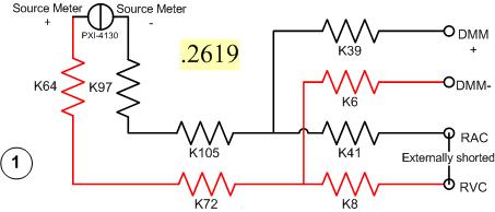
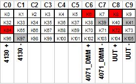
I have a problem with a PXI-2530 switch card work in matrix mode 4 X 32. I need to determine the resistance of the pairs of specific relay within the matrix. I have a PXI-4130 and a PXI-4071 in the same chassis, so I take measures 4-wire in a configuration like this...
Resistance symbols represent relays in the switch. Here is a representation of matrix-style switch routes I use. (This should look more like the interface of soft face before switch)
The two diagrams represent so how I take my measure. I shorted outwardly columns C8 & C9 (shown in the first graph), I am sourcing 500 microamps of current and toggling the current source for a positive and a negative measure, I am able the voltage with the DMM. For the above measure I'm mesure.2619 ohms. This should be of course my resistance of the relay K8, K41, as well as Terminal block and wiring.
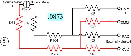
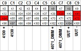
Here's another schema. This should measure the resistance of two same...
All I have changed is routing between the meter from the source. Here's the view from the matrix...
With this measure I'm mesure.0873 ohms. I can have the same resistance as the first example except getting a very different measure.
It gets even more interesting. If I had to take 4 pairs of wires, I use here, there are 16 possible configurations. I took each of these measures, and half of them gave me environ.25 ohms while the other half gave me environ.09 ohms. I tried this on a 2nd chassis and got the same result. My data are in the attached sheet. (My examples above are rows 1 & 5.)
Taking the measure of how we are, all these measures should be substantially the same. I have a current source constant, (I even tried a crimp in instead of the 4130 and got the same result.) and the meter is high impedance. If I had a pattern for the PXI-2530, I could do a little more analysis to know why I get various measures. Is there some diodes clamp on the lines or columns in the matrix? Something external must act solange this circuit. If I can find out what that is, I could determine my resistance to relay to a quantifiable level of uncertainty.
Any help would be greatly appreciated.
Greg
It seems that I can't remove. The correct message was placed here...
Once again, my apologies for the incorrect positioning of the post.
-
Why E-mail stopped to relay my ISP?
I had my server running beautifully for serval months now. Last Friday, we noticed that some of the emails from our office did not reach their destination in a few minutes. Some would take hours and days. I could very well receive emails. We organize our company e-mail service in the House on a mac mini with OX 10.11.6 5.1.7 server. In case of problems today, I determined that the implementation of relay on the server is correct, but when I need local customers send the relay through our server it fails. If I uncheck this requirement, local customers can send very well.

The requirement of relay works well until last week. Without going through this may very well at the moment, but it seems counter-intuitive. Is there a problem with the installation of relay that needs work to update or rinsed out properly?
Now that I have turned off the outgoing 'Through ISP mail relay' switch I received a call from a person in Texas who does not work for us. He received an e-mail from his home account to our domain name.

It doesn't have an e-mail account in our system. How is this possible, and is this power flowing through our mail server?
-
Transpose lines / columns entered for Matrix
Hi all
Read a few pages on the forums of the community about me little challenge, but come to the conclusion that using the OFFSET would be the way to go, but I'm struggling with the syntax. Maybe, I'm thinking of it (Note: similar to copy paste n + transpose into excel). The idea is to, first, build the frame of the matrix by using the information in table 1 and 2 below, then laster, fill the inter connection of cells with the data of table 2.
The first step is to transpose the first two columns of table 2 for the columns in a table (highlighted) two first is OF 2 + is the main reference OF-3 and this is the main reference and so on.
The number of entries in table 2 will increase with time, so it's easy to update with here simple fill.
Played with "SHIFT" without success - based on a similar problem posted on an earlier version of numbers / iWorks. So, I am convinced it can be done this way - of ideas or suggestions would be very welcome.
Thanks in advance
Perry

Select the source table (shifts right in your screenshot), then select the menu item "Table > transpose the rows and columns."
now, select the area you want to move, copy
now select the destination, the dough
-
Radio frequency for associated relay Netatmo Thermostat change
I have been told by Netatmo to change my Thermostat Netatmo associated relay Radio frequency as there seems to be problems with interference causing the relay to stop working. Can someone tell how can I do that. Thank you very much!
In airport utility, go to the wireless tab... from options wireless at the bottom of this page and then you will see the wireless channels


I put the 5 GHz channel because she was using a channel in Australia which is BAD.
Personally, I doubt that this will fix your problem... It is more likely caused by too wireless signal around you and the TC as a poor place.
Use simple... No, apple names recommended... anyway, no spaces and pure alphanumeric characters and also pure alphanumeric passwords.
-
mail server rejects emails because it does not relay. What is the relay?
I'm trying to set up an e-mail account on my imac, iphone and the ipad. Implementation was a success on the imac and can send and receive messages to test. However, in putting in place ACCT even on phone and Tablet returns an error msg "... the recipient ' my @me.com apple" was rejected by the server because it does not relay ".". " The sender email acct server rejects email or the receiving email server rejects it? Regardless, how to fix? IOS and newer and operating system are installed on all devices.
Relay, this is how mail servers send messages between them. You are not a mail server, you will need to login with the appropriate credentials. The configuration for sending mail is bad for the account that you are using. These settings are found under SMTP, the main server at the bottom of the account settings. The automatic configuration of iOS is perhaps not good for the server. Since he works on the iMac, you can use it as a guide. Look especially for the SSL port number required and the type of authentication (password, etc.).
-
Why do I get 'access denied relay '.
When you try to send an e-mail for the first time (new computer with windows 8.1), it gave me this error message: cannot send.
Relay access denied.You have your configuration of SMTP server for the password = none.
You must go to account settings, scroll to the bottom of the list of accounts until you find the outgoing (SMTP) Server
Enter and change the settings of the SMTP server to the = Normal password -
Cannot start a new conversation with relay of sms on the Mac or iPad.
Very strange problem and I have tried seemingly everything. SMS relay works fine on all my Apple devices. I can send and receive messages either SMS or iMessage. However, I can't start a NEW conversation with relay. I can only answer to the conversations that are already started. (does not matter if I started or the other party)
When I want to send texts to my boyfriend who doesn't have an active conversation in the list of messages I have to text him to my main iPhone (that the relay is activated on) and after that the convo appears right in messages on mac, the other my iPhone and my iPad, and I can continue to send messages from any device.
I tried to close off the coast of relay and allows once again. Restart the phone. Restart the mac. Disabling iMessage on the iPhone. Ensure that all devices are on the same wifi network. A lot of things that shouldn't matter...
A few tips here after a reset of the iPhone?
Also note that my iPhone is running iOS 10 beta 2 now, BUT I had this problem for some time. Long before I had the beta version.
Well, that's disappointing...
-
I have a gen apple 1 dot matrix printer and I need a driver software for it
I have a matrix printer of gen 1 Apple and I want it to work with my windows computer but I can't type good driver software.
does anyone know of a good driver for the printer matrix apple for windows?
What type of port is has a 'printer by points Gen 1 Apple? If it has a serial port Apple, you may have a secondary problem is that it connects to a typical Windows PC?
-
Premium HP: HP Premium - problems with adding an additional column to a matrix
I have version 2015 7 28 (8151) firmware and can not be updated any further because I have only the Android app.
I wanted to add a 4th column of a 3 by 3 matrix, which is stored in M1.
I did this way:
ADDCOL (M1, [0,0,100], 4); Add the fourth column: [0,0,100]
Another way to do it is:
M1 (1.4): = 0;
M1 (2.4): = 0;
M1 (3,4): = 100;
Both give the same result when I look in the catalog of the matrix.
Also when I enter the House finds out or make some operations with it.
Strange is that in the catalog of matrix the first matrix has a content of memory that is about twice the memory of the second matrix.
Nothing to concern about one would say.
But when I use the first matrix in the advanced version of TRIANGLE_P it gives lines output instead of triangles, and the second is behaving normally.
I seems to me that there is something wrong with the ADDCOL command.
I think that this has been corrected already past the 8151 must therefore in there when / if the android version is updated.


Maybe you are looking for
-
Characters: Leaving color like that tab
I gave everything in the nagging incessant and updated upgraded to Firefox 12 (from 3.6). Now I am trying make the appearance exactly how I like it. I have used Personas to get rid of the transparency effect and found a color that I liked: the proble
-
'connect to the iTunes store' keeps popping up on my iPad at random.
A message "connect to the iTunes store" keeps popping up on my iPad, even if what I'm doing has nothing to with the iTunes store.
-
HP Photosmart 5520: Printer already done
I've implemented on behalf of HP plugged and it shows no added device. When I try and add my printer, I get an error saying that the printer is already done and I need to remove this device. How can I work around this error because there is no printe
-
My Msn chat doesn't work anymore, it says that he needs Windows Update platform...
-
The problem starts just today when I opened my computer and started playing with the no sound
So, basically, as the title says, my video games sounds is not recognized by my volume mixer. The problem started only today when I opened my computer and started to play with no sound. At first I thought that I had cut all the sounds but then I chec