Measure the time of the rising edges of a digital stream using a USB-6341
I have a DAQ USB-6341 map.
I use Measurement Studio (writing code in c#) on a Windows 7 computer.
I'm relatively new to the DAQ cards, programming, so I could ask something that is obvious (sorry if this is the case).
I went out a stream of digital pulses to an analog output channel. I wired this channel to one input of the meter channel. I am able to measure the number of edges upward to the inlet of the meter channel (since the digial flow is continuous, the number of rising edges increases with time).
I would like a time stamp of each rising transition and I like to keep these timestamps in a table without ever growing (or maybe bin these timestamps in a histogram).
Set up the meter channel to provide the timestamp data? (rather than just count)
Thank you for your help.
WRB,
The meter must be able to measure the relative time between the different edges of your signal. To do this, you will take care to set the meter to measure time. It will measure how long a full period of your signal takes. You can configure edge that you want to start with. You'll want to set up your timed 'implied' measure. This sets up the meter to automatically take action whenever a period is over. While it's not exactly a timestamp, you can find the distance between two edges by adding the time periods between the banks in question.
I see another technique that you can use. This would put the counter to edges of County one of the basics of time of your device (it has 100 KHz, 20 MHz and 100 MHz bases long). Then configure the task to use your signal as a sample (configuration to use rising edge) clock. Whenever the song occurs, you will get the number of ticks ticks selected timebase that took place at that time. One thing to note here, however, is that the counters are 32-bit wide, so your code will have to manage the overthrow of this charge if you are using a fast time and base running for long periods of time.
Hope that helps,
Dan
Tags: NI Hardware
Similar Questions
-
How can I measure the output of a sensor pwm ultrasound using the module or 9403
How can I measure the output of a sensor pwm ultrasound using the module or 9403
Khalil,
When you say 'measure' the PWM signal, exactly what to tell you?
You're looking to measure the frequency or cycle of the signal function? You count the edges of the PWM output increase? Looking to control the waveform?
With reconfigurable FPGA hardware, it is up to the user to define the function of the physical i/o on the FPGA chip. By connecting the signals as Adam suggests your digital pulse will be brought to the cRIO. In your FPGA program, you define the function. You can set a base counter or transfer digital data from single point to welcome you cRIO for floating-point more complex treatment. Example FPGA programs are located in the http://www.ni.com/IPnet.
Hope this helps, please post any additional questions.
-
The best way to channel multiple steps using NI USB 6009?
I'm new to labview and I am trying to acquire multiple voltages of several channels and spread them out on a chart. It seems impossible to do it at the same time since the NI USB 6009 has only one pair of ADC.
The only way I ever came with is to use daq assistant to support significant tensions one by one and then make it loop awhile, but y at - it any delay during the move between channels?
And there at - it of best ways to acquire data from multiple channels?
If you have specified multiple channels (i.e. Dev1 / ai0:ai3) with a single DAQ Assistant, then this is the right method. The inexpensive device has no simultaneous inputs, so you will have to live with the slight delay of channel inter.
-
uninstall the wireless printer. Try to install using connection USB installed on a network.
Try to install HP Officejet 6500 wireless by using the USB connection. Installed on a network. How do I uninstall and let Windows identify as new material on a USB connection?
Turn off the broadcast of your wireless router signal. Shut down the PC. Menu using the printer configuration to remove or change the SSID. Then turn the printer off and connect it to a USB port (this implies that all the necessary software has been installed). Now turn on the computer and turn on the printer. Once the printer has been detected the turn on your router.
Never be afraid to ask. This forum has some of the best people in the world to help.
-
How can I measure the time between the two edges of successive increase, using digital input...
Hello
I'm trying to measure the time in seconds between each two successive rising edges on a digital input.
So far I managed to detect the rising edge, increment a counter at each rising edge and take the time during which the increase is edge
all I need now is subtract edge currently rising from the previous era of edge rising to calculate (T), which can be 1/frequency and display in real time for the user.
but I do not know how to do this

Can someone help me please!
Note: while I am in a position varies between 200 ms - 2 seconds
-
How can I measure the time between each two successive increase edges, using digital input?
Hello
I have tried two measure the time in seconds between each two successive rising edges on a digital input.
So far I managed to detect the rising edge, increment a counter at each rising edge and take the time during which the increase is edge
all I need now is subtract edge currently rising from the previous era of edge rising to calculate (T), which can be 1/frequency and display in real time for the user.
but I do not know how to do this
Can someone help me please!
Woah!

Sorry Apok, but your code becomes much too complicated and salty. I don't think that all records to offset or Boolean conversion/operators are necessary at all.
If you want to measure the time between two keys so it's another (much less complicated) way. It simply records the time when press button in a registry change, then compares the two.
-
How to measure the distance using script
Hello
Is it possible to measure the distance of any document in photoshop using the measure tool, using the script. Below the steps required by me. Hope I'm clear in my communications.
I've searched the forums, but couldn't find appropriate answers.
1. open the Photoshop document
2. allow the user to draw the line with measure tool
3. the alert distance
RGS
Anish
This only works with CS5 because it now uses the tool instead of a path rule. But it solves all the problems talked about in this thread and many other differences between the original function and the data in the info panel.
It returns a custom with angle and length properties object if there is a rule tool line in the active document and not of the indefinite. I didn't know if the length must be a unitValue or number in the units of the rule settings. I went with number because the Panel info has different number of decimal places for the different units. And as the Panel assigned the corresponding graduation info per cent the length value is empty
function getRulerToolLengthAndAngle() {}
points of var = [];
points. Start = [];
points. End = [];
var / / desc = new ActionDescriptor();
Var ref = new ActionReference();
ref.putProperty (charIDToTypeID ('Rprp'), charIDToTypeID ("RrPt"));
ref.putEnumerated (charIDToTypeID ('Dcmn'), charIDToTypeID ('Ordn'), charIDToTypeID ('Trgt'));
desc.putReference (charIDToTypeID ('null'), ref);
var / / desc = executeAction (charIDToTypeID ('getd'), desc, DialogModes.NO);
If (desc.hasKey (charIDToTypeID ('points'))) {}
pointList var = desc.getList (charIDToTypeID ('points'));
var startPointDesc = pointList.getObjectValue (0);
points. Start.push (startPointDesc.getUnitDoubleValue (charIDToTypeID ('X')));
points. Start.push (startPointDesc.getUnitDoubleValue (charIDToTypeID ('Y')));
var endPointDesc = pointList.getObjectValue (2);
points.end.push (endPointDesc.getUnitDoubleValue (charIDToTypeID ('X')));
points.end.push (endPointDesc.getUnitDoubleValue (charIDToTypeID ('Y')));
var RES = {};
res.toString = function() {return "RulerTool news" ;};}
Pointed var = points.start;
var points.end = b;
If (pointed [0]
var a = Math.max(pointA[0],pointB[0]) - Math.min (pointed [0], b [0]);
var o = Math.max(pointA[1],pointB[1]) - Math.min (pointed [1], b [1]);
var ang = (180/Math.PI) * Math.atan2(o,a);
If (pointed [1]< pointb[1]){//negative="">
Ang = - ang;
};
Res.angle = ang.toFixed (1);
} else {}
var a = Math.max(pointA[1],pointB[1]) - Math.min (pointed [1], b [1]);
var o = Math.max(pointA[0],pointB[0]) - Math.min (pointed [0], b [0]);
var = 180-((180/Math.PI) Ang * Math.atan2 (a, o));
If (pointed [1]< pointb[1]){//negative="">
Ang = - ang;
};
Res.angle = ang.toFixed (1);
}
If (app.preferences.rulerUnits == Units.PERCENT) {}
Res. Length = "";
} else {}
var c = Math.sqrt + ((a*a) (o * o));
var length = new UnitValue (c, 'px');
length.baseUnit = new UnitValue((1/app.activeDocument.resolution),'in');
Switch (app.preferences.rulerUnits) {}
case Units.PIXELS: res.length = length.as('px').toFixed (2); break;
case Units.INCHES: res.length = length.as('in').toFixed (3); break;
case Units.CM: res.length = length.as('cm').toFixed (2); break;
case Units.MM: res.length = length.as('mm').toFixed (1); break;
case Units.POINTS: res.length = length.as('pt').toFixed (1); break;
case Units.PICAS: res.length = length.as('pc').toFixed (2); break;
}
}
return res;
}
}
var getRulerToolLengthAndAngle() = Info;
If (info! = undefined) alert (' the ruler tool angle is: ' + info.angle +'\nThe length is: ' + info.length);
-
I tried using the recovery disk and tried to use a USB key to try to get it started but my computer still jumps her.
Hello
"It is not always shut-down.
It's not enough information to that is, if it stops at other times other than when you use the recovery disk.
"tried to use a USB key to try to get it started."
Have you changed the Boot order to make the DVD drive 1st in the Boot order if you tried to use the DVD player in your computer?
And to boot from USB devices, you must have USB Boot active in order to boot on your motherboard and also 1st in the boot order
Read one of these methods:
http://helpdeskgeek.com/how-to/change-boot-order-XP-Vista/
http://pcsupport.about.com/od/fixtheproblem/SS/bootorderchange.htm
In a large number of computers, by pressing F12 at startup is a way to change the boot order.
And in these Forums, when a poster has issues with the manufacturer recovery media, the recommendation is to contact the manufacturer for the aid that the manufacturer provides this software.
See you soon.
-
Count the number of rising edges in table 1 d
Hello
I wanted to measure the frequency of a pulse signal using a MCC DAQ via libraries ULx in Labview. I have two methods to do this:
1. use the analog inputs:
Since data acquisition has only 1 ADC, I use a commune VI acquisition for all channels and create a multi-dimensional array with different channels in rows 0-15. Then divide them by using the function "Array Index". I think this split removes the parameter 'time' to the wave, since it is now a table 1 d. But I already know that there will be 1000 samples each 100 m everything I want to do now is to count rising edges using a function and divide it by the 0.1 to obtain the frequency in Hz, but I don't know how. Can anyone help?
2. use the input frequency meter:
Because I can't use the DAQ assistant, I have to use the CI frequency-> counter 1ChanNSamp DBL 1 d in the ULx library. There is no reference to take aid to and I do not know if this method is good. I have no way of knowing since I do not have a signal generator. In addition, it does not work so far.
Help, please.
Thank you!
Thank you.
I note in your first post it is seems to want to get readings of speed about 10 times per second. To get a resolution of 1 Hz frequency direct count you need to get at least 2500 counts in a range of counting at the highest frequency. This means that you need to have at least a second. Measures of the time are another option.
Some preliminary calculations:
Period at 2500 RPM = 2500 Hz is 400,000 Americans.
Period at 2499 RPM = 2499 Hz is 400,160 to the United States.
You need to be able to resolve a difference of 160 ns period. To do this directly requires 6.25 MHz sampling rate. It is 25 times faster that your DAQ card can enjoy.
What other options are there? Consider only your Information.vi extract. He uses techniques of Fourier transformation and interpolation to find the frequency of a signal. I set up a quick test VI to check this. Using a sampling rate of 10 kech. / s and 1000 samples per read (10 reads per second), it has easily resolution of less than 0.1 Hz at both ends of the range of speed and largely independent of the amplitude. This is the way to go.
Lynn
-
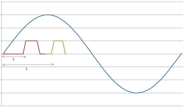
I have a sine wave of 50 Hz and a pulse of the signal on the same chart. The difference in phase between the two is between 0-90 degrees.
Now I need to calculate the time difference between (when the sinusoidal wave passes through zero volts) and (when the pulse increases). The frequency will remain about even for the two signals.
The request is for a three-phase generator. In simple terms, when the difference in time between the passage to zero of the sine wave and pulse increases increases, it means that the load on the generator has increased.
I am a novice user of LabView (version 9, 2009), maybe it's a very simple problem but I was pulling on my hair for the past few days and couldn't understand anything. Any help would be greatly appreciated. I use DAQ USB-6008 to measure these tensions and the impulse of the generator and a sensor
I have attached a jpg file (a graphic that I just did with excel to explain). The time 't' is what I'm trying to measure
See you soon
Zdzislaw
Awais.h,
For problems of this kind I recommend start writing the granular steps you would take to manually fix this problem. You can't say LabVIEW (or any programming language) If you can't succinctly describe the solution to your problem.
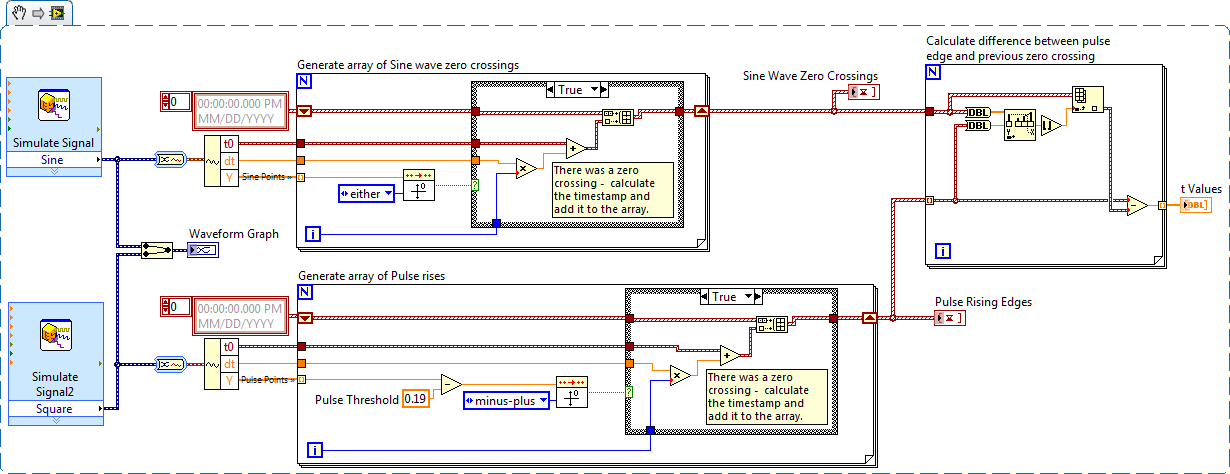
The I want to address this problem is to:
- find all the zero crossing points and edges on the rise
- for every rising edge find the difference between the timestamp and previous passage by zero
Here is an implementation of this algorithm LabVIEW:
-
Measure the time between two digital pulse
Hello
For a non-critical calendar application, I need to measure the time interval between consecutive TTL pulses, ranging from the order of 0.5 s for a few seconds, with a low accuracy of +/-10-50ms. The interval being measured varies between the rising edge of the first pulse and the front of the next and so on.
I have several input lines I need to deal with. Because it's a critical machination low cost, I don't want to use digital counters for each line, so I work with an acquisition of data USB6008 and have connected the input rows TTL on the digital inputs of the device. Avoiding will be sufficient.
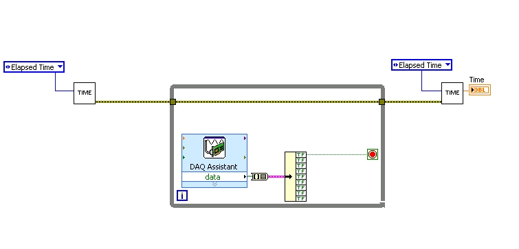
I found a good example of VI on discussion forums that does almost the same thing, only it uses instead of the DAQ Assistant user input. The VI works including the time the program going on in a while loop. I replaced with the DAQ Assistant output (a channel) user input in the hope that it is still work.
When I run the program in "run once" mode, it seems to work perfectly. However, in "continuous run" it measures only a very small interval, probably just the time between two samples. I think it has something to do with the help of a while loop in combination with the DAQ Assistant. Anyone who has any suggestions how to solve this problem?
Thank you!
OK... first of all, you should never use the button "run continuously. I wish that NEITHER would be to eliminate it, but told me that it is sometimes useful for debugging. If you want your program to run over and over again, use a while loop with a stop"" button.
If I'm reading your code correctly, you make your initial moment, and then collect data from data acquisition. When one of the channels is "T", you stop your loop and the end time of capture. (By the way, why you convert your table to a cluster? Why not just index the appropriate channel in the table directly?)
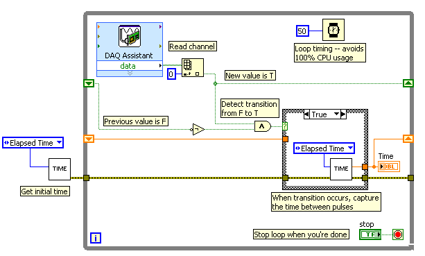
Since you want to capture the time between two consecutive pulses, you need to know when a transition has occurred... i. e when your digital line went from F (no pulse) to T (pulse start). This will give you your forehead. Right now, all you're doing is looking for a value T - so you have no way of knowing if you are looking for to the previous impulse again, or a new impetus. You also burn 100% of your processor with the way you have your programme in place.
You need a small loop delay so that your VI is not 100% of your hogs CPU time. Given that you can live with an accuracy of 50msec, what I suggest that you use.
See attached picture for you give an idea of how to implement. He will probably need some refining operations, but it should point you in the right direction.
I hope this helps.
-
Measure the time in seconds each time run you a VI
Dear people,
I'm trying to measure the speed of a wheel using a magnetic sensor and other settings in the vehicle. What I also need to document in my project is the time elapsed (in seconds) each time that you run the program. Is there a way where you can measure the elapsed time in seconds in labview?
Any sort of suggestions or examples would be useful.
Below is an example of how I wanted my final to watch output file.
Time (sec) | Speed (mph). Acceleration |
0 23 5
1 24 6
2 25 7
Thank you in advance!
Rahul-
Hi iZACHdx,
That's what I was looking for exactly! Thanks for the simple example.
Thank you
Piraux
-
Hallo,
I use the following system:
- OR PXI-1044 with controller NI PXI-8109
- OR PXI-2564 switch module to turn on the monitor of my test device
- Data acquisition multifunction NI PXI-6259 to measure the signal that responded to the questionnaire jump
The two cards are the same - PXI trigger bus. For both, PXI-2564 and PXI-6259 I use DAQmx to set the reading and writing of the channels.
Now, I want to measure the time between the digital output, my unit turns and the analog input, which measures the response of my system.
I can't do work by myself, please help me!
I thank Ludwig.
Hi Ludwig,.
If you can't give us any VI we have difficulties with to help you.
Because I Donat knowledge how your program is mounted it is not easy to know where you should enter signals.
Here's a question similar to yours:
http://forums.NI.com/T5/LabVIEW/best-way-to-measure-time/TD-p/178704
and 2 external links:
http://www.ehow.com/how_8698983_measure-time-LabVIEW.html
http://objectmix.com/LabVIEW/385152-how-can-i-use-LabVIEW-measure-time-between-analog-pulses.html
-
How to measure the execution time of a specific to a VI process?
Hello! My VI has two processes: compression and edge detection image and I'm trying to measure the execution time for the process of detection of edge of my VI, but I don't know how to do. Please give me some ideas on how to do it. Thank you!
There are several ways that you can do.
-L' one is using the number of cycles before and after your vi to get time like here: http://digital.ni.com/public.nsf/allkb/6F6B9F4E149C80578625652800784764
- or use the profiling: https://zone.ni.com/reference/en-XX/help/371361H-01/lvhowto/profiling_vis/
Edit: If you're open to suggestions:
-You have not to load the image inside the loop instead, make him outside of the loop.
- And I see of many IMAQ buffers are not removed properly. You can have everything at once by Images (No) by logging in to Boolean TRUE: http://zone.ni.com/reference/en-XX/help/370281P-01/imaqvision/imaq_dispose/
-
Measure the time between the ridges of the periodic input signal
We have built a circuit which is supposed to mimic an Exercycle. We have an IR switch and a spinning wheel, the rccb meets a comparator circuit and the output of the element of comparison, we have running in LabView. We successfully were able to measure the number of rotations of the wheel and the total distance travelled by the wheel, but are struggling to measure speed. We cannot find a way to measure the time between picks in real time, which we could then divide the wheel circumference and calculate the speed in real time. The VI I posted has a square wave simulated rather than the signal we receive on our circuit. Thanks in advance for the help.
Jon and David
I think you're overloading the things trying to get the time between two pulses. Instead, you can use the VI Express your measures and select frequency for her custom. Then, you can multiply the circumference of the wheel of the frequency to get the speed.
I hope this helps.
-Christina
Maybe you are looking for
-
Audio delayed or does not stop when you run a video. So I used RESET. Lost bookmarks & homepage & ADBLOCK and who knows what else. So I just copied ALL the files from the old profile on my desk in the new found under troubleshooting. Put everything b
-
Handles wood for the F5 with registration and a magnification button?
I came across several good options for handles (smart) wood with only the record start-stop button, but it would be great if there was a way to have a second button link to the viewfinder magnification option.
-
PXI-8532 DNET card is not detected in MAX
Hi all I use NI PXI-1031(4 slot PXI chassis). I have the following cards in the respective locationsSlot 1 = controller PXI-8106Slot 2 = PXI-6259 card (I)Location 3 = card(DI,DO) PXI-65094 = Card (DNET) PXI-8532 accommodation Max (Measurement & Autom
-
HELP WITH SIGNING in GAMES FOR WINDOWS live
I get an error of connectivity. My status as a network of games for windows live in the games are as follows:1 Internet IP address: not singed in2. the address of the link system: not active3 Upnp not connected How to solve the problem
-
Vista activation code error 0xc004F063
Diagnostic report (1.9.0027.0):-----------------------------------------Validation of Windows data-->Validation status: invalid licenseValidation code: 50Validation caching Code online: n/a, hr = 0xc004f012Windows product key: *-* - XY9X3 - JDXYP-6CJ