Measurement of angular position with encoder in quadrature and NI USB 6281
Hello.I have an application developed with labVIEW 7.1 and 6014 OR for the measurement of angular position using encoder quadrature, where are used 3 sons - one of them connected to the source, second to the OID (0 or 1) and a third to digital ground. I can't use the same application or NI USB 6281.Now connections, I would like to know how I can create a similar application in labview 2009 and how to make the relevant connections for NI USB-6281, which is a mx NI DAQ device. Please suggest. Thank you.
I have my loan application. I understand there are big difference using LabVIEW 2009 and NI USB card, compared to the previous version I was using THE LabVIEW 7.1 and a traditional daq. The difference, I should say that wellness is both in terms of simplification of code and the accuracy of the result. I was a little surprised, showing results. Thanks a lot to JB for your time and sharing those pieces of details.
I can well after awhile my code in the forum. Hope this helps someone like me looking for a similar application.
Tags: NI Hardware
Similar Questions
-
A measure of speed high speed with encoder in quadrature and NI 9401 on cDaq
Greetings,
We use an encoder in quadrature with 360 pulses/turn on the tracks (track A and B) and no trace of Z to measure motor speed at startup. Data acquisition, we use a NI 9401 in 9178 cDaq chassis and a pc with LabVIEW. The problem is that the start-up period is relatively short (less than 1 second), during which we measure speed as precisely as possible. The speed range is from 0 to 10000 RPM.
What type of measurement method that you would recommend.
Here are a few methods that we have already tried:
-Measure with DAQmx CIFreq--> high frequency with 2 counters: speed measurement, but with a very big mistake (+ 166 RPM).
-CIFreq DAQmx--> wide range with 2 counters: good speed data but more slow measurement,
-CICntEdges DAQmx (counting separated the two lanes, speed conversion): very incoherent speed data.
Thanks in advance for your help.
Matej
I would definitely say a 4, the measure of a low freq called option with 1 meter. (Frankly, I've never been
fond of this name because it is useful for freqs much higher than what I expect most people think "low freq".) This
is the method that I almost * always * use for frequency of counter measures. It works really well to capture transitional
variations in speed.
10000 rpm and 360 cycles/rev, you are looking at a maximum frequency of 60 kHz. The frequency measurement mode 1 meter
There will be 80 MHz internal clock by encoder cycle edges, then you will get more than 1000 strokes per measure. The point
that means only 1 number of quantization errors, you can expect<>
Further, you can average overall, say, 10 samples to you give even better accuracy and you could still be a data capture
rate significantly higher than the probable bandwidth of your mechanical system. (The average would just clean the jitter and noise and would not
Hide answer true mechanical characteristics).
-Kevin P
-
Jdev 11 g: problem with encoding of characters and resource bundle files
Hello
I use Jdev 11.1.1.0.0, IE7 and resource group files (* .properties) to translate the application into other languages.
The CommonBundle.properties file contains the following:
BUTTON_CLOSE_LABEL = schließen
BUTTON_COMMIT_SHORTDESC = Speichern der Lavaggio
======================================
The ss and A are the German special characters.
When I run the application of Jdeveloper (with includes WLS 10.3) then the files are copied in... \ViewController\classes\view.
With this action, the content of the propertie files go to:
BUTTON_CLOSE_LABEL = Schlie\ufffden
BUTTON_COMMIT_SHORTDESC = Speichern der \ufffdnderungen
========================================
On another PC with the same environment (XP, the language in the BONE, Jdev 11.1.1.0.0, settings...) the same action modifies the content of the properties file
BUTTON_CLOSE_LABEL = Schlie\u00dfen
BUTTON_COMMIT_SHORTDESC = Speichern der \u00c4nderungen
========================================
That said, when I run the application on my PC the ss of characters and are displayed wrong.
On another PC, the same application displays the correct characters.
On my PC the two DIFFERENT German characters are sequence ESC replaces it with the SAME (and evil).
Question: Which parameters are responsible for the translation of some sequences ESC-German special characters when I run or deploy an application?
BTW: The problem is the same if I deploy the application from my PC.
concerning
PeterOK, here's my findings.
1. it depends on the Encoding setting in tools > Preferences > environment > Encoding!
2. a file created with the same set of characters translate correctly.
3. a file created with a different set of characters will not translate correctly.
4. to use Unicode all the UTF-8 encoding and create all files with this endocing. Translation will not work correctly.-olaf
-
Can I download and install Windows 7 pro with a product key and the USB (No .iso or CD/DVD)
So my hard drive failed, Dell can replace it but none of the software. I have OEM Windows 7 pro and Office 2010 versions, which means that I (somewhere) product keys but not record. Maybe Dell recover disk will work, but it's 7000 mile more away. I've seen links to download install. ISO (I hope that its official?) but I would have no way to burn to CD, so my question is...
Can I download a bit of Installer for Windows 7 Pro 64 to install from USB and my existing product key?
What happened to Microsoft Office 2010 Home & student?Thanks for your help guys.Can I download a bit of Installer for Windows 7 Pro 64 to install from USB and my existing product key?Check out the link below for assistance on above:What happened to Microsoft Office 2010 Home & student?Check out the link below for assistance on above: -
Use the angular position of the encoder to trigger Digital out
Hello
I am a novice user of labview, I have access to three modules, two NI9201 and a NI9401.
I have an angular encoder is used to measure the angular position of a crankshaft of engine, what I try to do is to use the encoder to trigger a digital camera (spark in the motor event) at a certain angular position. For example, I would like to start up (or) stalled, then I want to change that to + 5 degrees on the encoder, etc.
So far, I am able to read in the angular encoder when the engine is running, I am also able to output digital signals even if I can't find a way to connect the two.
If anyone has an idea how to do this, it would be greatly appreciated, I am attaching my VI.
Thanks in advance,
Nick
Hi Nick,
I hope that the vi attached you will get on the right track. It's just a general concept.
The while loop will work until you press the stop button.
I guess you'll need a spark by revoultion.
This VI is really just an If/Then
If the encoder value is equal to (in this example) zero,.
Trigger digital output.
I know that I have a wire cut, but I didn't know how to get the angular position of you DAQmx.
Let me know if this help. (Also let me know if I'm off-target)
Good luck
Bill
-
With the help of a NO-9401 read the angular Position and trigger a reading I
Hi all
I am writing some software dependent vs angle chart and to the monitor when the buttons are pressed. The software allows all DAQ lines to be configured so that multiple configurations data acquisition can be used.
Currently, I peut use my NOR-9411 read the angular position of my quadurature encoder and trigger the playback of my entry (measured with a NEITHER-9219 or 9237) load on a rising edge of A or B input terminal analog. Also, I can configure the software to do the same thing with a card OR-6259.
My problem is that when I switch to a NO-9401 to read my meter task, I can no longer use the input terminals A or B to trigger my analog input. I get error-200414 saying that the entry A (PFI0) is an invalid clock source.
I know that the 9401 is configurable by nibble for input/output lines0:3 and 4:7, but how that affects the ability of a trigger, a route line PFI?
Measurement and Automation Explorer shows it as an acceptable way of PFI0 AI/StartTrigger and AI/SampleClock.
I joined the my code section that defines the tasks and that causes the error. You take a look in the Utilities folder and open the Tasks.vi create.
I am writing in LabVIEW 2011.
Thanks for any advice,
Rob Afton
Test lab engineering intern
Found my answer here if anyone has the problem:
-
cDAQ9184 for the measurement of the angular position...
Hello
It works now... Thanks for the customer support OR. The measure of the angular position uses a signal generated internally by using a counter ("/ cDAQ1/Ctr1InternalOutput").
ARO
Ilkka
-
How to measure the angular velocity, the angle and trigger using a gyroscopic sensor breakout board and LabView data acquisition?
There is a single channel data acquisition code which measures the angular velocity, angle and flexibility using a gyroscopic sensor breakout board and acquisition of LabView data attached to this, I need a help to creat two-channel data acquisition code?
Hello
Attached is a vi that you can use in order to read the measured angular position of an encoder.
If you need more examples on the tasks that you can develop with NOR-DAQmx and LabVIEW, you just need to open LabVIEW and click Help > find examples > Input and Output material > DAQmx > entry counter.
Kind regards
-
Problems with encoder motor switching noise readings
Hi all
I wanted to ask advice with a hardware problem which seems to be pretty common.
Here I describe my request:
We are controlling an electric actuator for robotics application. We use encoders to take position readings, and we need to perform analog acquisition for other measures (for example, the force measured using strain gauges).
The problem is:
In summary, I have problems to properly acquire position readings of a linear encoders quadrature and also a few analog inputs. The cause is the switching noise generated by the drive motor that we use (which is an engine without Stricker of CC Moog BN-23-23).
Our acquisition platform is an NI PXI-8106 with a PXI-1042 q chassis. We have two possibilities to acquire the signals. We have a multifunction DAQ series NI PXI-6259 M and a FlexRIO NI PXI-7951R with one module DIO NI PXI-6581R.
The switching noise have a frequency of 30 kHz. In a scope, we see a series of peaks of noise which are present only during a short period of time (approximately 1/10th of the duration of the noise). The rest of the time the noise is not present.
The Accelnet amplification module that powers the electric motor gives us a clock signal synchronized with the noise (whose frequency is approximately 1/4 frequency noise). This clock signal provides a way to solve the problem of analog acquisition. We can use this clock to make an acquisition stamped with an external clock in LabView connecting the clock on a spit of PFI or FPGA card. But the noise is also corrupt this clock signal (we get an error daqmx us warning of possible defects in the clock signal and also to stop the acquisition). I believe that to solve the problem of encoder we can also solve the problem of the analog acquisition.
In the encoder readings noise makes our County to counter upward or backward gradually fast enough. We can get an increase in the position of about 10 cm per second with no appreciable movement in the linear actuator.
It would be a great help if someone could put the solution he uses to solve this problem.
Thanks in advance for your help,
jespestana
PS: I stress my conviction that we have a hardware problem, because we have only bad readings when the electric motor does not work. I am therefore convinced because we have already done reading encoder and analog with the help of other players, such as hydraulic cylinders. So, I think that it is not a problem with our software (of our LabView VI).
Hi jespestana,
I don't know why the noise could be the cause of your encoder can increase more slowly... However I have a suggestion on the map of the M series (6259):
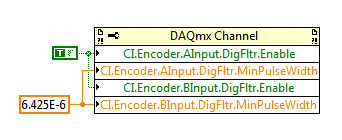
M-series cards have a digital filter integrated on the lines of the PFI (see the user manual of M series). Looks like the noise is a series of 3 ~ US of impulses (1/10 to 1/30 kHz). Of the available filtering frequencies that you can set on your M series is 6,425 US, which must ignore the impulses (high or low) that are less than 6,425 US. You can configure the digital filtering with a property node DAQmx:
One caveat is that the driver only allows you to configure the digital filtering for entries counter on M Series devices. For example, you can use a digital filtering directly on your task of encoder, but not for your sample clock HAVE. A workaround can be found here, which is to set up a dummy counter job to define the PFI filter for your task to HAVE. If you use the same PFI line for your encoder and the task to HAVE it, you should be able to just set up the PFI filter through the task of the encoder and worry for the workaround.
Regarding the RIO Flex, I think that you could implement something similar on the FPGA, but I'm probably not the best person to comment on this subject. It would be probably a lot more work to use the DAQmx API's built-in filtering.
Best regards
-
What is the function is used to read the form of angular Position a task?
I created a task DAQmx in MAX. This task configures a counter on a PCI-6259 to counties of A and B of a coder with the angular Position. Which function to use to read the value since I am more counties of reading I read the position?
Thank you in advance for any advice!
Hi Izzy,
I created the task UP. The task takes in the counter of an encoder input and converts it to angular position. Always use the DAQmxReadCounterF64 function to read the meter? I'm guessing that I made and that the function returns the angular position, rather than the raw numbers. Not sure if.
Thank you for taking the time to answer.
Regards-
John o ' c
-
Encoder 6351 PCIe and quadrature + voltage sensor.
Hello! All the experts,
I am considering 6351 PCIe to use as a counter and all of catch data.
The question is how to use the input channels equipped with PCIe-6351 quadrature encoder and correspond to voltage sensor data.
1.
Ex)
Each quadrature encoder pulse count, take each value of the voltage with the value counted (Crank angle)
Rising edge of a pulse of 1 2 3 4 5 6 7 8 9 10 11 12 13
Value of sensor vol. 0.1 0.6 0.8 1.2 1.5 1.9 2.1 2.4 2.8 3.0 4.0 4.2 3.5
I would like to know how to get the data using 6351 PCIe quad. function...
2. in addition,.
Do you know how to directly transfer the values of the voltage sensor of PCIe 6351 VI FPGA?
Ex)
Value of sensor vol. ===> PCIe-6351 ===> VI FPGA (analog channel in FPGA)
Could you give some advice?
All tips are welcome!
Thank you very much!
Best regards
Hyo
Hi Hyo,
To the best of my knowledge, the PCIe-6351 isn't any FPGAs; FPGA is generally available on the platform of RIO and R series cards. As such, I'm a little confused by what you mean when you say that you want to transfer the values of voltage for the FPGA VI.
If you use our API of DAQmx LabVIEW, you can use redeclenchables Analog Input to collect a finite quantity of samples of your card for the acquisition of data each time a trigger (e.g. a pulse encoder) is received. This article has a bit more information:
http://digital.NI.com/public.nsf/allkb/14843A49037D7E368625769C006F7A65?OpenDocument
I hope this helps!
-
Measure Z to a battery encoder encoder pulse frequency to measure the speed using a 6034 E card
Hello
I want to measure the speed of a motor that has an encoder to encoder hung on battery. It provides impulses 3 A, B and Z I uses a PXI 6034 E card. I wanted to know if there are any examples/ideas that could help me with this (I'm new to digital programming in Labview). I moved to NI Daqmx 9.8 recently of the old version that has supported the existing codes and therefore being updated the code. I also want to know if an external clock source is needed to do this. This.
Hello
There are several examples in the finder OR example (you can get here by going to help > find examples in a window of LabVIEW). You can browse examples of Encoder on input and output material > DAQmx > entry counter. You should be able to find some examples that will be useful.
In addition, this link is a good resource to get started using DAQmx: http://www.ni.com/white-paper/5438/en
Thank you!
-
A motor with encoder closed loop. Can I connect an other encoder without using an engine?
Thanks to LabVIEW with a PCI-7332 and an UMI7774 interface to control a stepper motor with encoder feedback. System is configured in closed loop for the control mode. You will need to add a different encoder to the system without attaching a motor. I'm validation of encoders to each other. Is this possible? Should what kind of latency I expect? I have attached a simple vi. Need to buy one before the answer.
Thank you
You can just plug the second encoder to the second slot without an engine it. Then you can use reading encoder Position.flx to read its position or do whatever you want with it. What about latency times, how are you trying to go under?
-
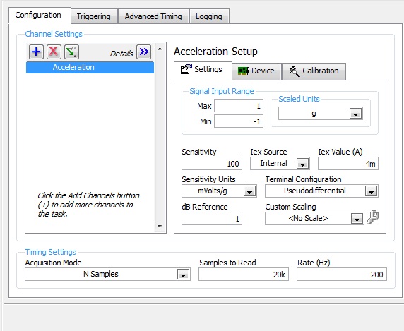
Noise measurement of an accelerometer with card PCI-4461
Hello world
I'm trying to measure the noise of an accelerometer, except with a card PCI-4461.
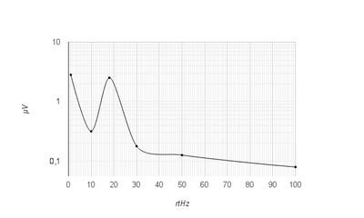
First of all, I measured manually this noise with the help of a HP35665 signal Analyzer. I get something like this:
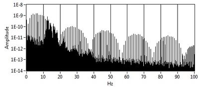
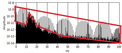
And now with LabView and the PCI-4461 map, I get this:
My question is: Whence this part? And how to remove it? (Since there is no with the signal Analyzer)
I'm using LabView 8.5.
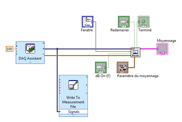
This is how I configured the DAQ acquisition:
and it's my VI:
Thank you in advance for help
Arthur
-
simultaneous acquisition of the accelerometer and a measure of a rotating machine encoder.
I want to make a simultaneous purchase of the accelerometer and a measure of a rotating machine encoder.
So what National Instruments data acquisition product must be chosen to do this capture.
Sure that if your accelerometers do not need power IEPE (maybe you have an external power supply for the accelerometers) and if the voltage sensor is located in the voltage of the sensor of the 6221 range.
Maybe you are looking for
-
Is it possible for my tags in Windows to reflect also on Mac and vice versa?
Hello! I recently bought a MacBook and a new hard drive. I'm organizing my files on my Windows desktop. I already started to organize into folders, adding tags and authors and all that. But when I checked on my Mac, the metadeta was not there and vic
-
Re: How to enable virtualization on Portege R500?
Dear allMy NB R500BIOS version 1.60 04/03/2008Operating system Windows 7 RTMApplication Virtual PC and XP modeAfter installing, it says that I need to enable virtualization technology?I installed Toshiba HW setup, but I don't see the option of virtua
-
The memory in a MacBook can be improved?
I'm considering buying a MacBook s at hsn.com. They come with 4 MB of memory. Can they be upgraded at the helm of Apple Geniud?
-
OfficeJet Pro 8630: how to install additional color on the 8630 printer cartridges
I just bought an Officejet Pro 8630 with additional color print cartridges. I went through the instructions but I do not understand where they tell me to insert additional color cartridges. I've looked everywhere but I still can't find where they n
-
WINDOWS 10 Download now, upgrade later?
Every day I get a pop up telling me I can download now and install later. I ignored it for a while and now it's popping up more often so I decided to keep quiet by uploading it on an external drive to treat it after I'm done with my end of month and