Measurement of mass flow of a cell
Hello!
I have a load cell that I currently use to measure weight, but I would get the mass flow rate at the same time, I am able the weight.
I tried using shift registers to get the current weight value and the old and then subtract x 1 - X 2, and I did the same thing with time to get dt. So I can split with the other. It's just that I don't get the mass flow on the right. I guess I have to calculate my data acquisition data acquisition rate and how quickly the while loop runs.
I don't have to work and do not know what I have to divide my signal with or if I need to slow down the loop.
I know that this task should be easy, but I'm stuck and need a little help. Also, I can't find examples for this task on the forum.
I enclose the My .VI if you would take a peek.
Best regards Marulind
Hello!
I managed to solve it with registers at offset!
Greetings Maurlind!
Tags: NI Software
Similar Questions
-
Entered analog PCI 6251 not extent of tension of a mass flow controller
Hey,.
I have a data PCI 6251 M acquisition with a break in Council SCXI 1302.
I'm trying to measure a 0 - 5v analogue output voltage from a mass flow controller (check picture of PIN)
When I measured with a digital multimeter the voltage of the flow signal (PIN2) and common signal (PIN12) I get a stable right tension between 0 and 5v depending on the flow set up. I can control the amount of the charge by providing a data output set point PIN8 and common PIN12 of the 0 - 5V analog signal.
Now when I connect the signal flow PIN2 and on my DAQ signal common PIN12 AI and AIGND, I don't get readings on my labview VI of the AI. In addition the flow does not meet the setpoint voltage, it get stuck in a range of values no matter how I vary the OD 0 - 5V of data acquisition in setpoint PIN8 and PIN12 common signals.
I have to add that I tried different ports HAVE with results of sam, and I also tried to measure my supply voltage with my HAVE and all the good work.
It seems that the entry of AI affects the AO output voltages to my charge. What would cause this? That would be a problem of impedance adaptation?
Management or ideas are appreciated.
Thank you
Ali T.
Update for anyone that might interest you:
I not connected to the ground of the power of the mass of the signal of FJA FJA.
Once I did the acquisition of data reads all data as expected.
So it turns out not to be a problem of acquisition of data, OR at all, but a game of question for my part, as I suspect is the case with most of the problems.
Jeff Merci for your comments.
Ali T.
-
To connect to the Net material MKS Alta 1480 mass flow controller
I have a mass flow controller MKS Alta 1480 (MFC), manual of MFC, Labview 8.2 and the NI PCI - CAN card. I know that the MFC wired correctly because I can work using another program on the PC that uses the deviceNet interface. I want to talk to her through Labview. Everything looks OK Explorer measure. I have the range OR DNET. I know that the MACID. I downloaded the EDS of the manufacturer.
Here is what I am missing: a general idea on the DeviceNet interface. Is there a code of example out there that could help me get started? There are tutorials on how to understand the Dnet Protocol? I'm used to control serial--> response devices. I don't know anything about the class, object, attirbutes.
Thank you
Joe
Normal 0
Joe, you can read the MFC object sensor analog-S Flow value.
Class Id 49 0 x (31), Instance Id 1 (0x01), attribute Id 6 (0x06)
The default data Type is integer and units of data's counties
Normal 0 if you want the reading of the assembly object, you're going to have establish polled i/o connection, then read DeviceNet IO.vi allows you to read feeds.
-
Faced with setting up a connection RS-485 for a for OR cDAQ mass flow controller
I'm an absolute beginner from the ground up tries to connect the port RS-485 to a mass flow controller (MFC) Instruments Sierra for the NOR cDAQ.
The planned route of the person in front of me set up for the connection is:
(1) cable MFC COM1 to Interface Ethernet 4 ports for RS485/RS422 (DB-9 to DB - 9)
(2) Ethernet 4-port Ethernet Interface RS485/RS422 OR cDAQ cable
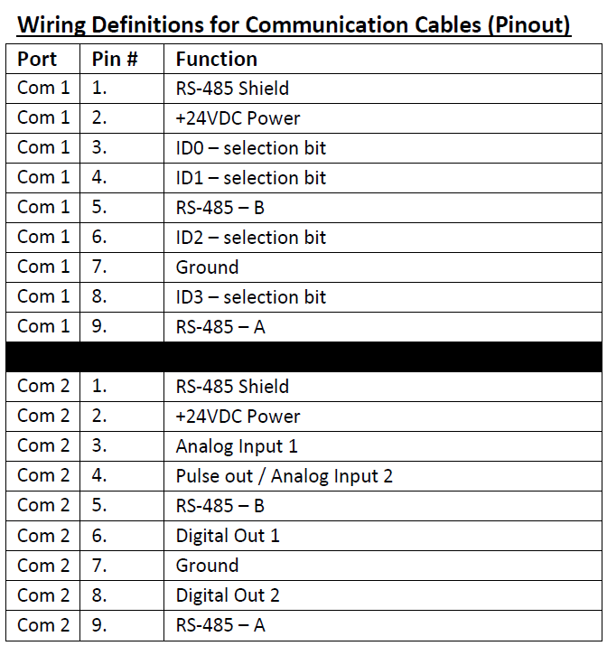
I'm fighting to understand exactly how the pins should be doubled for the 1st part of the interface. For MFC COM1 pinout is given below:
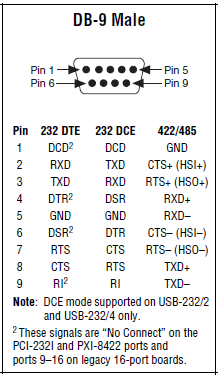
The pinout for DB-9 male, shown in the quick reference Guide series of NI is illustrated below:
I do not know what pins on the side MFC should connect to which pins on the side of the ENET-485. The manifesto is ground (PIN 7 to pin 1). In addition, I'm stumped. Try to read references online has just served to confuse me even more at this point...
Any help would be appreciated!
Follow-up: I bought a B and B Electronics ULinx USB converter to RS - 485 9 pin as well as a cable of Sierra Instruments. I was able to confirm communications between the cDAQ and the MFC using own Sierra HMI as well as through NOR-MAX provided.
-
Bronkhorst gas mass flow controller is not powered
Hello
I have connected the mass flow controller of company BRONKHORST using RS232 to USB to my PC connection, but not flashing LEDs on mfc. I don't know if he needs additional power or not? MFC has only RS232 PIN.
I have attached the mfc manual and my labview program
Any suggestion or help would be appreciated.
Thank you
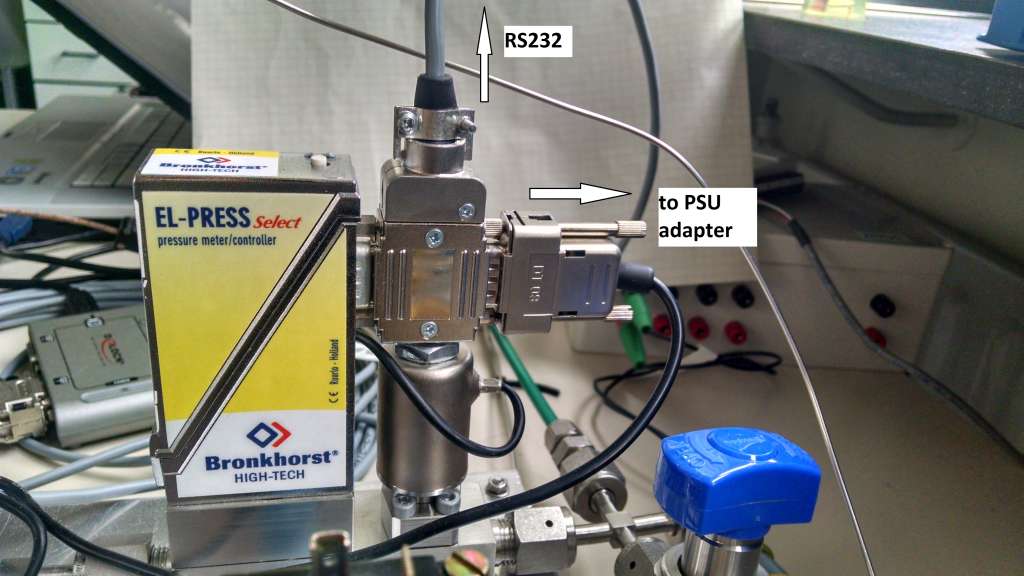
Contact Bronkhorst, you need a special cable that connects the MFC to power and in addition it has a RS-232 cable connection. A RS232 can power your device only.
Take a look at my configuration (it is a regulator of pressure, but is the same for a MFC):
-
Connection to a mass flow of the FVL-2612 of Omega controller
Hello
I have an Omega FVL 2616 (0-500 SLM) mass flow control. I'm putting in place through LabView for most flow record. The manual for the unit account documentation to use HyperTerminal, that works.
I tried using the wizard Instument IO, but in vain. I have the connection established a RS232 connected to COM1 on the back of the PC. When I select this devicea and indicate the Wizard "read and analyse" it just times out.
I'm not the most savvy with LabView, but get a grip on the basics.
I'm looking to retrieve a scroll bar to control levels of flow and a feed for actual throughput that can be stored in a document.
Baud: 19200
parity: no
Bit: 8
stop: 1
Any help would be greatly appreciated.
Concerning
Edwards_NSG,
I suggest using the basic read and Write.vi series. This can be found in the finder of the example.
If you want to use the wizard of I/O (I think that the example will be really easy) you don't have to send some sort of command to the device? If so you have a writing stage in the wizard of e/s?
-
Mass flow controller of control using USB 3105 (calculation of the measure)
Hi all
I hope this helps!
-
mass flow meter and controller
Hi all.
I have the mass flowmeter and controller of Bronkhost. I tried to control using RS232 communication and I found labview progrma developed by Bronhkost to set the desired value and read the measured values. These works of independent Labview programs and when I try to set and read the measured values by connecting one after the other. I can adjust the temperature setting to the controller, but I can't read the measured values. Therefore, I here enclose labview programs, developed by Bronkhost. Any body who has done it before please help me with my troubles.
Concerning
just solved!

-
PowerShell for Excel cell error
New to PowerShell and looking for someone who may know if it should work, or if I have some other issue going on. I get all the data to write, but vmhost data fill the date as I want. My code is below the error.
$Excel = new-Object - comobject Excel.Application
$Excel.visible = $True
$Excel = $Excel.Workbooks.Add (1)
$Sheet = $Excel.WorkSheets.Item (1)
$Sheet.Cells.Item (1,1) = "Hosts".
$Sheet.Cells.Item (1,2) = "VM".
$Sheet.Cells.Item (1,3) = 'Clusters '.
$hostcount = get-VMHost | Measure-Object | select count
$Sheet.Cells.Item($intRow,1) = "$hostcount".
Exception definition "Item": "Exception from HRESULT: 0x800A03EC.
D:\powershell\workinpro.ps1:19 char: 1
+ $Sheet.Cells.Item($intRow,1) = "$hostcount".
+ ~~~~~~~~~~~~~~~~~~~~~~~~~~~~~~~~~~~~~~~~~~~
+ CategoryInfo: NotSpecified: (:)) [], SetValueInvocationException)
+ FullyQualifiedErrorId: CatchFromBaseAdapterParameterizedPropertySetValueTI
Thanks for any help that you can give the new kid on the block
This seems to say ExcludeProperty and not ExpandProperty.
The disadvantage of the IntelliSense
-
Links between cells in a table
I need text stream in a table using InData (this automatically reformatted text). To do this, I need the text to flow from one cell to the other. I don't see how to tell the table to let me do that. Is this possible? I did this in Quark without problem, and I simply cannot see clearly in ID!
Thanks in advance for any help,
Emma
Alas, no.
-
Hello
I would like to make a single pulse program that sends commands different sets at different times during the duration of the parent VI. Orders must be sent only once at the beginning of the precise time (see attachment) and not constantly all the time duration is reached. I tried various methods (counting time and the use of the different Boolean operators, the elapsed time express vi, pulse generators, etc.), but still I can't find a perfect structure for my needs. In addition to sending the commands I want to follow other ports series continuously for the measurement of the data during execution, so waiting simple functions do not work. I want to send the command sequence must be repeated several times (variable) which translates an interpretant pulse program. But it seemed to me a simple task at the beginning that I am lost right now, because different approaches work in part, but neither gives a satisfactory result so far.
I'm pretty new to LabView and I'd appreciate any ideas how to implement these functions in a safe and clean way (scalability, etc.). This program will serve to the configuration of the mass flow controllers (MFC), whose dose of different gases at different concentrations. I would use avoiding the necessary time for dosage are minutes and hours, so no trigger of millisecond is needed.
Thanks a lot for your help and your advice.
Thomas
Even if you use the same serial port, you can always set up a loop that makes communications and use issues or events send orders when the other loop has expired for this event. It shouldn't be so hard to get this to work.
-
6008 OR using Labview 8.6 variable output voltage
Hey guys,.
So my goal is to create an output voltage of my USB 6008 OR which can be set from 1 - 5V in Labview. (This output goes to a mass flow controller that varies its pressure based on an entry 1 - 5V) I'm using Labview 8.6 and far I used the DAQ to create analog output of fishing, but I can't figure out how to get a right voltage DC output. Is this possible? Also to measure the output so I connect the cable on the + and - or the + and gnd? Please help me!
The tension of desire is just a digital control.
You should probably just stop and take one of the free tutorials. A digital control is a very basic concept.
-
With the NI 9205 module Max sampling rate - problems
Dear friends,
I develop a project of lv, which makes and control system of engine dyno. The material is CRio-9022 with other cards and also 9205 for AI. There is an encoder for angle attached to the motor shaft with 3600 chatted by Tower as well as an index to indicate the end of a revolution. the output of the encoder is measured by card 9411. The speed of the motor is 1500 rpm. I measure pressure data and couple when I receive a 'tick' of the wheel. This means my sampling rate for pressure and torque each is 90KO/s.
but I was not successful to lead it. The program is great and I can show them, but I believe that there is a problem in the choice of material for the task. With the data of pressure and torque of the 9205, I also measure other channels for the controller output mass flow and temperatures. So in all I use 8 channels of the 32 available. But only the pressure and torque are acquired at the wheel-driven sampling rate. the rest are acquired about 5 times per second.
Since the 9025 is a multiplexing ADC, 250K sampling frequency is divided by the number of channels accessed = 250 K/8 = 31 K samples/channel. With this in mind, I decided to acquire data of pressure and torque with each beat 3rd rotary encoder, essentially on 30K samples/s sampling. However, I see a large amount of noise.
So I decide to average more than 1 second cycles (so the engine runs at about 25 cycles/sec, I averaged over this issue). The resulting pressure and torque graphics do not match with those measured by an oscilloscope in terms of amplitude but the frequency and shape is correct.
I noticed an interesting feature in the charts. When I pass interpolation between the points, I see several curves made by points instead of a continuous locus of points. Accordingly, I find that the acquisition is slower than necessary, and so there are less number of points sampled as required. These points are not synchronized 25 cycles I have on average and therefore the separate "curves". It is because of the possibility that some points receive a higher number of 'contributions' several times (when you add), the neighbouring points.
so I conculde that the 9205 is not fast enough to do the job. also noise, perhaps due to crosstalk or gosting when the mux changes channels. the impdences output pressure and the couple are of the order of 10 K ohms.
the Labview code outline: well, there is a vi FPGA, which takes the rotary encoder ticks and sends a signal to the case of each 3rd tick. The signal contains a 16-bit integer, indicating the number of ticks. This signal is sent to a 1 element FIFO. This fifo is read in a parallel while loop, where it remains awaiting a new element. The while loop bed fifo, where data are available, takes a measure of pressure channel. A node memory of the method is called to provide data according to contained in the index number equal to the number of ticks to signal fifo. Then he adds the current pressure reading to the reading of the memory and stores the sum in the same memory location. Thus, an array of elements of 1200 is formed, where each elemnt is a sum of the values taken of more than 25 cycles. This memory is transferd to a dma fifo and reading side host. is done similarly to involved couple. host-side the fifo is read and divided by 25 to get the average. This average is displayed on a waveform graph.
Please check the attached file to get an idea of the problem. Sorry for the long post.
Please suggest if you understand the problem and suggesstions or solutions.
-
guidance inertia temperature control
Dear people,
I would ask for advice from experienced people in control theory.
Recently, I'm working on a very interesting device, it is called inertial guidance vacuum calorimeter (there is a type of isothermal calorimeter). I'm doing a new LabView program for this camera, and I try to increase its stability/accuracy as much as I can. This calorimeter can measure heat sample level micro-watt powers. The principle of measurement is the following (see attached diagram):
We want to measure the heat flowing from the outside door-sample, this is done via Peltier (thermoelectric sensor) sensor. To obtain valid data, temperature must be very precisely constant everywhere in the calorimeter (isothermal method). The inner parts of the calorimeter thermally protected against ambient temperature with blank shields and high radiation. Double room empty closed circulates water through a heat exchanger, the heat reservoir.
For thermal stability, there are 3 loops controlled:
1 control loop. : this controls using PID, (method of classic platinum resistance 4W) constant water temperature
2 control loop. : this is the first step to stabilize the temperature of the inner part, PID loop classic platinum resistance and drives a pump to Peltier heat between the support and the "base". This can achieve only a constancy of temperature around 0.1 mK.
3 control loop. : when the ultimate stability is reached with the control loop 2, it is off, and his conduct of the current production constant value. Now the loop3 begins, and that's the tricky part: there is a cylindrical copper heavy 'inertial mass' with high calorific value (much higher then the base) standing on the base. Because it has a high calorific, even temperature fluctuations very tiny in the performance of temperature-controlled database a measurable voltage in the thermoelectric sensor between inertial mass and the base. This value is measured by the meter nanovoltage (Keithley). So I use this value to control the heat under the base pumps. In principle, if there is no heat flowing between inertial mass and the base, we are in thermal equilibrium.
With this concept, it is possible the stability of temperature range well below nanokelvins!
Recently, I play with the control settings, but only using simple PID controls (I have the PID toolkit). The method explained above is a kind of analogy of inertial guidance in mechanical control. I wonder if someone could give me advice or direction how I could further improve the stability of this control. Perhaps some more advanced control system? Feed-forward?
Thank you very much for the advice,
Kind regards
If I follow correctly, the feedback control loop 3 is measured using the Keithley via GPIB. And these readings take approximately 0.6 seconds. The control loop cannot work faster than the measurement system (unless you want a lot more unstable!). Most high precision instruments offer a compromise between resolution and speed. I took a look at the profile of 2182 and it seems you may have need of any resolution, so accelerate may not be an option.
The approach of bottle neck is probably a good with all that you have done so far. It will help you to avoid putting too much time into something that won't make much improvement.
Another thought: how noisy/drifty are power supplies/amplifiers driving Peltier devices? I worked on a system several years ago, where the objective was stability uK ~ 10 and noise and drift in the power circuits were the main limitations. Most of the engineers designing such devices never think of parts per million or fractions. Especially with the slow return of nanovoltmeter, drift or noise in the power circuts could be important. Also look at how the constant output mode that the external loops are open loop constantly.
Lynn
-
USB-to-serial VISA read problems
Hello
I'm trying to control several mass flow controllers attached to a hub series Alicat BB9. The hub is then connected to the computer via RS-232 series. The computer on that what is done is not a serial port, so an adapter series / usb is used. When it is plugged in, the computer (XP) recognizes the series / usb and requires a driver. I installed a driver from the manufacturer of the adapter, downloaded from the internet. The same driver is used on another computer (Vista) without any problem.
I am able to verify that the device is installed and operating correctly via the Device Manager. I am also able to see what the device COM port is turned on. Opening OR measurement and Automation Explorer (MAX), I am able to see the COM port listed under serial devices. I am able to validate the port settings and open a VISA session with the device. However, any time I try to read from the device, what happens to expired. I get the error xBFFF0015. I have for the parameter timeout at 5000 and 10,000 without change.
When you run a VI that is used in the laboratory to control the same configuration, I can trace the error to a VISA read Subvi. The returned 'buffer' is not a value and will raise an error. I can plug the USB key into a laptop that has the same VI and it will run without problem. The Subvi "VISA read" return a value when running on the laptop.
I'm under LabView 8.5 and 4.4 of VISA.
If anyone has a suggestion that could get this to work I would appreciate it a lot. Also, I am a graduate. student who is working on this issue and my understanding of LabView is not terribly large, so dumbed-down responses would be nice

Thank you for your help.
Connor
Thank you for the follow-up. However, I was able to solve the problem already... It was simply a driver update that solved my problem. The driver being used is "Prolific usb-to-serial" and version 1.. I upgraded 2.0.2.1 and it works fine now. I thought I had updated to the most recent before and apparently I had not... kind of delay. But thanks anyway!
Maybe you are looking for
-
Good question after Windows update on Satellite P100 PSPA3E
I encountered a problem with my sound card after a Windows Update. It became an old analog tuner with problems of dust on his volume knob. (this is a reference "sounds like" for those old enough to remember) I updated the driver to the most recent Dr
-
Internet LAN conection problem when power is connected - Satellite M70
Hello I recenetly bought a satellite M70 - 360. For some reason, internet connection (LAN) only works when the computer is running from the battery to the moment where you plug in the AC adapter, it is cut (you can also hear that there is some type o
-
A challenge simple error Bar chart
Problem is quite simple: XY1Err1Y2Err2 120.130.2 240.160.2 360.190.2 Y1, Y2 on the same plot showing the Err1 error bars and Err2 respectively to draw using the error Bar feature plot, AND (this is the difficulty), make a legend that shows Y1 and Y2
-
[fpga] Faster communication between FPGA and host in real-time
Hi all I received a card FPGA NI FlexRIO (SMU-7965R) installed on a chassis PXI (SMU-8135 embedded controller). I have an FPGA program to 40 MHz, and I use a real-time program to read a particular variable of FPGA on a regular basis. I do not stream.
-
My 50 d is about four years old. Its firmware is 1.0.7 and checked to see if there is an update of the firmware. I see there is a new firmware - 1.0.9. I have recently upgraded to Windows 8 but when I click on the upgrade it informs me that there is