mass flow meter and controller
Hi all.
I have the mass flowmeter and controller of Bronkhost. I tried to control using RS232 communication and I found labview progrma developed by Bronhkost to set the desired value and read the measured values. These works of independent Labview programs and when I try to set and read the measured values by connecting one after the other. I can adjust the temperature setting to the controller, but I can't read the measured values. Therefore, I here enclose labview programs, developed by Bronkhost. Any body who has done it before please help me with my troubles.
Concerning
just solved!
Tags: NI Hardware
Similar Questions
-
Entered analog PCI 6251 not extent of tension of a mass flow controller
Hey,.
I have a data PCI 6251 M acquisition with a break in Council SCXI 1302.
I'm trying to measure a 0 - 5v analogue output voltage from a mass flow controller (check picture of PIN)
When I measured with a digital multimeter the voltage of the flow signal (PIN2) and common signal (PIN12) I get a stable right tension between 0 and 5v depending on the flow set up. I can control the amount of the charge by providing a data output set point PIN8 and common PIN12 of the 0 - 5V analog signal.
Now when I connect the signal flow PIN2 and on my DAQ signal common PIN12 AI and AIGND, I don't get readings on my labview VI of the AI. In addition the flow does not meet the setpoint voltage, it get stuck in a range of values no matter how I vary the OD 0 - 5V of data acquisition in setpoint PIN8 and PIN12 common signals.
I have to add that I tried different ports HAVE with results of sam, and I also tried to measure my supply voltage with my HAVE and all the good work.
It seems that the entry of AI affects the AO output voltages to my charge. What would cause this? That would be a problem of impedance adaptation?
Management or ideas are appreciated.
Thank you
Ali T.
Update for anyone that might interest you:
I not connected to the ground of the power of the mass of the signal of FJA FJA.
Once I did the acquisition of data reads all data as expected.
So it turns out not to be a problem of acquisition of data, OR at all, but a game of question for my part, as I suspect is the case with most of the problems.
Jeff Merci for your comments.
Ali T.
-
Faced with setting up a connection RS-485 for a for OR cDAQ mass flow controller
I'm an absolute beginner from the ground up tries to connect the port RS-485 to a mass flow controller (MFC) Instruments Sierra for the NOR cDAQ.
The planned route of the person in front of me set up for the connection is:
(1) cable MFC COM1 to Interface Ethernet 4 ports for RS485/RS422 (DB-9 to DB - 9)
(2) Ethernet 4-port Ethernet Interface RS485/RS422 OR cDAQ cable
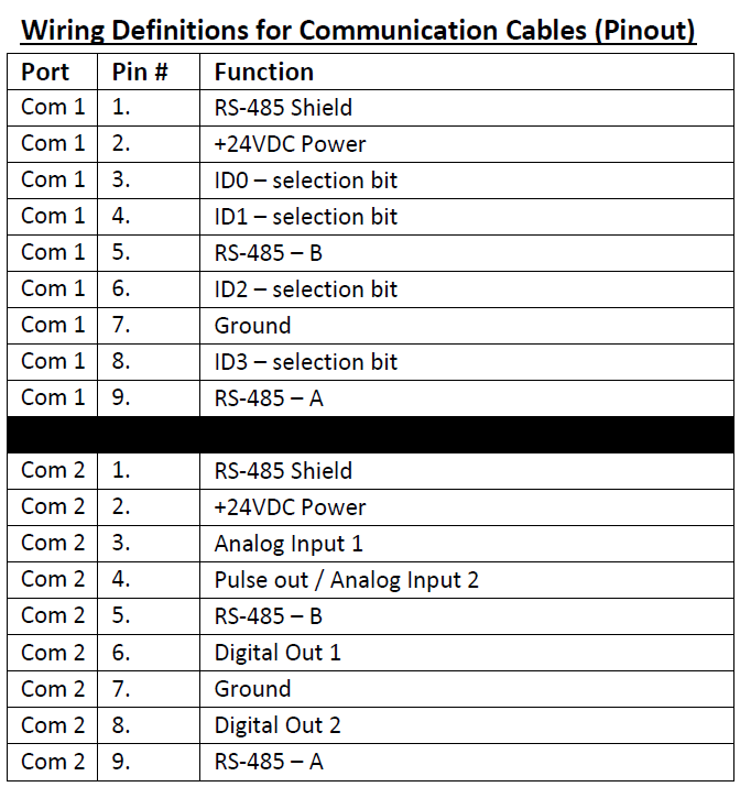
I'm fighting to understand exactly how the pins should be doubled for the 1st part of the interface. For MFC COM1 pinout is given below:
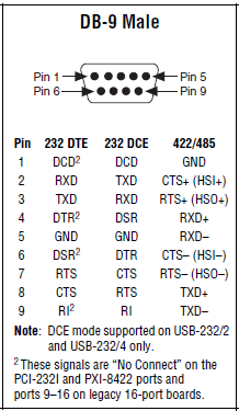
The pinout for DB-9 male, shown in the quick reference Guide series of NI is illustrated below:
I do not know what pins on the side MFC should connect to which pins on the side of the ENET-485. The manifesto is ground (PIN 7 to pin 1). In addition, I'm stumped. Try to read references online has just served to confuse me even more at this point...
Any help would be appreciated!
Follow-up: I bought a B and B Electronics ULinx USB converter to RS - 485 9 pin as well as a cable of Sierra Instruments. I was able to confirm communications between the cDAQ and the MFC using own Sierra HMI as well as through NOR-MAX provided.
-
Bronkhorst gas mass flow controller is not powered
Hello
I have connected the mass flow controller of company BRONKHORST using RS232 to USB to my PC connection, but not flashing LEDs on mfc. I don't know if he needs additional power or not? MFC has only RS232 PIN.
I have attached the mfc manual and my labview program
Any suggestion or help would be appreciated.
Thank you
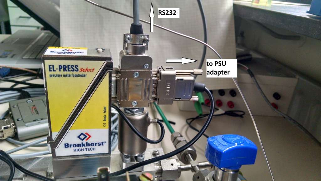
Contact Bronkhorst, you need a special cable that connects the MFC to power and in addition it has a RS-232 cable connection. A RS232 can power your device only.
Take a look at my configuration (it is a regulator of pressure, but is the same for a MFC):
-
To connect to the Net material MKS Alta 1480 mass flow controller
I have a mass flow controller MKS Alta 1480 (MFC), manual of MFC, Labview 8.2 and the NI PCI - CAN card. I know that the MFC wired correctly because I can work using another program on the PC that uses the deviceNet interface. I want to talk to her through Labview. Everything looks OK Explorer measure. I have the range OR DNET. I know that the MACID. I downloaded the EDS of the manufacturer.
Here is what I am missing: a general idea on the DeviceNet interface. Is there a code of example out there that could help me get started? There are tutorials on how to understand the Dnet Protocol? I'm used to control serial--> response devices. I don't know anything about the class, object, attirbutes.
Thank you
Joe
Normal 0
Joe, you can read the MFC object sensor analog-S Flow value.
Class Id 49 0 x (31), Instance Id 1 (0x01), attribute Id 6 (0x06)
The default data Type is integer and units of data's counties
Normal 0 if you want the reading of the assembly object, you're going to have establish polled i/o connection, then read DeviceNet IO.vi allows you to read feeds.
-
Connection to a mass flow of the FVL-2612 of Omega controller
Hello
I have an Omega FVL 2616 (0-500 SLM) mass flow control. I'm putting in place through LabView for most flow record. The manual for the unit account documentation to use HyperTerminal, that works.
I tried using the wizard Instument IO, but in vain. I have the connection established a RS232 connected to COM1 on the back of the PC. When I select this devicea and indicate the Wizard "read and analyse" it just times out.
I'm not the most savvy with LabView, but get a grip on the basics.
I'm looking to retrieve a scroll bar to control levels of flow and a feed for actual throughput that can be stored in a document.
Baud: 19200
parity: no
Bit: 8
stop: 1
Any help would be greatly appreciated.
Concerning
Edwards_NSG,
I suggest using the basic read and Write.vi series. This can be found in the finder of the example.
If you want to use the wizard of I/O (I think that the example will be really easy) you don't have to send some sort of command to the device? If so you have a writing stage in the wizard of e/s?
-
How to connect a magnetic flow meter to a 9203 module?
Hello
I have a magnetic flow meter, which gives me a measured 4-20mA signal. I'm reading this signal using the 9203 module. As he wrote in the technical data I have to use external power supply. I have 2 sons of my August flowmeter + and GND. I connect August + food + and GND to AI0 after that - from feeding to Com in 9203. I am doing everything correctly? I see not all values change.
Thanks for any help.
Hi Rodzynek,
Have you tried looking at the output with only a voltmeter digital or similar on the output?
It would be a good guide to tell you what really is the signal.
The 9203 gives a FXP signal in amperes, so if you expect 8ma your jpg shows 7.16 to 7,74 my which is close.
As I said earlier, I found that the signal of the 9203 is rather noisy and apply filtering to clean up the signal, I guess thatâs you measure the flow rate of the signal change very quickly compared to the sampling frequency 9203.
Also check if the WHAT GND is connected to the MASS of other output signals.
See you soon
Stephen
-
Magnetic sensor to the top of analog frequency AC for Turbine flow meter measurement
Hello!!
I use the following hardware configuration to measure a flow meter flow turbine.
Material: 1000 SCXI Chassis
SCXI 1102 voltage input module
SCXI-1303 terminal connection block
Flowmeter: output signal is the frequency of the alternating current (30mv peak-to-peak). Sensor is a magnetic sensor type.
I tried to convert the signal of output voltage in the area of frequency using the FFT, but I get the wrong data.
I wonder if anyone can suggest good troubleshooting techniques so that I can understand what is mess up my position or my technique of measurement in labview itself will not completely? (From my understanding I think that I can measure the frequency of the ac voltage signal generated by the sensor of the FFT. By measuring the frequency I can calculate the water flow)
I am aware that a potential cause might be the ground loop in the system. The signal is based solely on the SCXI-1102 with factory default bias and pullup resistior network. I see no other reason reading wrong or fault in my measurment. Also the flowmter is brand new and there is no risk of damage to the sensor.
I'm sorry if I'm missing out on any important detail to answer that I am relatively new on the techniques of data acquisition.
Thank you
Concerning
Aditya
It's conditioning of signals... and that's what you want to do, so it's not so far
And if your signal about 30mV Ridge to Ridge, it fits perfectly in the beach of crete to 200mV Ridge... I wouldn't say no need of amplification... the + 100mV is not a minimum of signal, this is the maximum signal in this range
Hang it up, take a measurement in single channel mode with one all 10kSPS sample rate take 100ms (1000points) and feed in single tone detection...
display with a graph of signal, stop the vi, in the rigth diagram, click the graph icon and create a constant, save that in a vi and post here if you need help in signal processing
-
conversion of turbine flow meter
Hello
My apologies for the query, but this software is all new to me. I have a cDaq-9188 8 medium chassis containing several modules including 2 off 9401 counter modules, I run signal express version 6.0.0.
My problem is that I have 3 miniature flowmeters turbine (GEMS units FT-110 series) which give various pulse widths depending on what is the 5V square waves. I brought to the entrance of my 9401 and look of good signals so guess that's my express configuration signal which is the cause of the problem,
I connected the + ve and gnd outputs of the flowmeters Com, DIO1 + Com and DIO3, DIO0 + Com on one of my 9401 cards.
I can see the increment in the number of pulses on measurement & automation Explorer when I run test for this module Panel and watch the chefs of edge that my system can see the pulse from trains.
When configuring the express signal I need it to read in l/min, 58-575Hz corresponds to 0.5 to 5 l/min, but I can't seem to convert the pulse in l/min.
If I select DAQmx acquire > counter entry > frequency it gives me the possibility of updated the custom scale, but every time that I run it I get the error signalling DAQ assistant upward. I tried many synchronization settings with no luck. The only time where I have this power as successfully is using counter entry > County of edge, but I'm stuck on how to convert l/min as it has no function of scale (I know!)
Any help appreciated.
I think that he is referring to l/min in litres per minute, and I guess the Freq of flow are the values of this compilation on the scale.
If this is the case; Carl, it seems to me you must configure a custom scale. You can do it in the channel settings tab in the DAQmxAcquire stage. Under custom scale select Create new, and then select map scale. Min/max Freq should match your flow min/max.I have attached a few screenshots for reference.
Let us know if we are on the right track, otherwise we might need more information; FOR EXAMPLE. file seproj and a bit more info on the flow meter (type of connection, the output signal, etc.).
In addition, a brief look at the documentation on this flow meter recommends the use of a pull-up resistance. Might want to look there as well. -
Help explain the flow meter VI
After a lot of tinkering, I seem to have developed an effective VI for use with a type/pelton turbine flowmeter. The flow meter outputs a stream of pulses which
can count on the counter of my 6501 line. Unfortunately this eureka moment happened somewhat by chance, and I'm hoping someone
could be kind enough to explain step by step or in terms very simple for beginners (me) works of VI, thank you.
Kind regards
GER
GER,
Welcome to the Forums and LabVIEW.
If you don't the have already made, please work through the tutorials online to get started with LabVIEW. The answers to some of the questions you may have are probably there.
A brief description of your VI:
1. the overall structure is a loop For. It works for the number of iterations that is connected to the Terminal in your case 5 N.
2. the calendar of the loop is determined by the longest time required for any part of the code inside the loop execution. On the first iteration, the DAQ Assistant configures the counter and starts measurement. On all subsequent iterations, he reads everything simply an indictment. On these iterations, the 25 les 25 ms ms expect will dominate. This VI runs approximately 40 iterations per second (for 5 iterations).
This means that the program will take place on 5 * 25 ms = 0.125 sec and then stops. If you run for more 1/8 of a second to help run it continuously button, STOP. Which is intended for certain types of troubleshooting only.
3. the table of waveform and the flow rate meter only shows the last value of the five iterations. (This suggests also that you use run continuously)
4. the registers at offset in this VI nothing do. The upper shift register calculates the cumulative number of the flow meter, but the result is never used. The underpass registry has nothing connected to the Terminal inside the loop on the left. It could be replaced by a terminal.
Suggestions:
1. in order to avoid using run continuously, replace the loop with a while for loop. Add a stop button on the front panel and connect it to the stop it real terminal in the loop. Move the graphic terminals of waveform and flow inside the loop.
2 check your pulse to the algorithm of flow rate. The time for the count interval must be considered. For example if the meter registers 25 pulse in 25 Member States, which represents 1 000 pulses per second. This isn't which will show your VI.
3. see examples of code that uses counters.
Lynn
-
How to connect an International ST75 components fluid flow meter to the DAQ system?
Hello
I am trying wire a ST75 meter to my DAQ system consisting of a device PCI 6052E DAQ, SCXI 1102 b card and a block to connect SCXI-1300. 1102 b has four 249 Ohm resistors connected to channels 0-3 for use with the current of the flow meter signals.
The flow meter has two output signals 4-20 my and RTN, SINK, SOURCE and com connections The documentation is not clear how to connect the sensor to the Terminal Board, other than to say if the two output signals is used, one of the sons of RTN are used. So far, I can not get the signal from the flow meter to work in LabView, so I don't know if I have it plugged properly. Currently I have 1 wire OUTPUT on the Terminal Board + CH2, CH2 - wire to the chassis ground terminal and the COM lead on the sensor.
Thanks in advance.
Towards the end of the manual there are wiring diagrams:
SINK/SOURCE/COM are used for pulse ouptuts. It seems that there are two outputs, one for 4-20mA temperature the other for flow.
The one you need (flow) conjnction with RTN wired to use the + and - (or COM) your DAQ hardware.
-AK2DM
-
Measurement of mass flow of a cell
Hello!
I have a load cell that I currently use to measure weight, but I would get the mass flow rate at the same time, I am able the weight.
I tried using shift registers to get the current weight value and the old and then subtract x 1 - X 2, and I did the same thing with time to get dt. So I can split with the other. It's just that I don't get the mass flow on the right. I guess I have to calculate my data acquisition data acquisition rate and how quickly the while loop runs.
I don't have to work and do not know what I have to divide my signal with or if I need to slow down the loop.
I know that this task should be easy, but I'm stuck and need a little help. Also, I can't find examples for this task on the forum.
I enclose the My .VI if you would take a peek.
Best regards Marulind
Hello!
I managed to solve it with registers at offset!
Greetings Maurlind!
-
How to sync analog & meter and two usb devices
Hello
What I want to do is synchronize the analog inputs and an entry on a device (USB-6009) meter and then synchronize this device to a different USB USB-9211.
I had a quick glance at the Web site and there are a few articles to the knowledge base on how to do these operations independantely (IE synch and synchronization channel) but I'm not sure how to bring it all together. My concern is that the USB-6009 case has only a single meter (which double as the PFI?) and it is generally used for the signal synchronization on the slave device? Used to say that I won't be able to use the meter to measure input? The USB-9211 a there a PFI connection?
Any suggestion would be appreciated.
See you soon!
Hi David,
If you want to synchronize and always stay USB, you will need to look at the chassis USB 4 9174. With this, you can get a digital I/o module, for example the 9401, to interface with chassis backplane and synchronize the frame on another device like the 6009. Another plus, it could ask, is that the bottom of basket 9174 meters integrated into the chassis, which have more capabilities than the meter 6009 and are accessible via the same DIO module that you use for synchronization. This seems to be the best route to go because of the capabilities that you are looking for.
-
Vs (standalone chassis and controller) chassis
main difference b/w the chassis and independent chassis and controller , for example
and
What is the best?
The 9138 is a standalone chassis, running Windows or OTR.
The 9178 is just a chassis holding your Modules of e. You must have a computer connected to make measurements.
And questions what is the best, can only be answered if we know your needs.
In any case, I would recommend to contact your local office of NOR and speak with a technical sales representative.
Christian
-
sez no authority trying to run AVG or Malwarebytes - every 1/2 hour or if some "prog system? NTauthority or Services and controller app sez he has a problem and the computer shuts down
Hello
- What is the full error message?
- What were the changes made to nfore this question?
- What exactly do you mean by "no authority running avg or malwar bytes?
It's a possibility that there is a startup program that is launched with a command line and it appears.You need to perform a clean boot to find the program that is causing and then disable or remove.
How to configure Windows XP to start in a "clean boot" State
http://support.Microsoft.com/kb/310353/en-us
Note: When you have finished troubleshooting, proceed as explained in the article to reset the computer to start as usual.
Maybe you are looking for
-
Need new drivers and utilities for Dell Inspiron 530 2007
Drivers & utilities I have a 2007 Dell Inspiron 530 and my driver and utilities disk cracked and will not work. How can I get a hand on a new disk of driver and utilties?
-
I get a pop-up that McAFee has found a virus, Trojan BackDoor Generic! CVO
I get a pop-up that McAFee has found a virus, Trojan BackDoor Generic! CVO. When I try to restart a McAFee scan, it shows no virus then, but later I'll get another pop up indicating the virus again. How can I get rid of the virus?
-
Does garbage collection occurs in the region of PERM of Java Heap?
Hi guys,. I am a new Member to this forum, my name is Javin Paul and I'm a Java programmer. I have a question related to the garbage collection in Java Does garbage collection occurs in the region of PERM of Java Heap? According to my knowledge PERM
-
Comments and account standard failed to load
My dell laptop-1569 win 7 64 bitWhen I try to load comments and standard account, don't charge not bot log off... there in the problem of the OS?
-
A12E5 error: I get this and can not download software (paid) InDesign
Can anyone help? I desperately need to get concrete results on InDesign and I can't seem to download on my MBP.I just paid for an annual subscription to InDesign online and receive an error message stating that I have an A12E5 error, after less than