Modbus Help!
Hello
First of all, I get a time-out error 6101 when I run my code, I read the threads and I always get this error message. Maybe it's the data I'm typing that I don't know. My camera is an ADAM 4024. Maybe I need help with my setup.
I'm trying to control a power supply through my camera.
Channel 0 controls channel 1 current and voltage.
I first want to have 0 Volt / ampere when I start then apply 2 volts / 1 amp to the next step? But I'm not sure how to proceed with modbus.
The manual provides the following information:
40001 channel 0 read/write address and displays the current value
40002 address 1 read/write channel and displays the current value
I believe that my starting address is 40000 so I entered 0 as labview starts at 0? Is this right?
And I should use function3 read registers operating.
I do not know what data to put in my records if I use write mutiple or amount of data, if I use read the registry?
I have attached a vi, but I don't know if I need two masters query.vis one to write many and one to read holding register. Help, please
Thank you.
Tags: NI Software
Similar Questions
-
You must look at the manual and to determine how the controller uses register set. What I saw with Watlow for example, is that the registry is multiplied by 10, set point as the set point can have a decimal. In your case, you must set the registry to 123 to 12.3. I also saw that some values may be represented by two records, which represent the binary value. Format is usually described in the manual. You can try to read the registry and see if the value is meaningless as well.
-
Hello Labviewers,
So I plugged in just a couple of the Honeywell UDA2182 controllers to my computer via an ethernet connection. I have established communication using modbus (specifically the Datalogging and Supervisory Control of i/o Modbus server module) and I can say that reading through the computer.
My problem is that everything is in some weird alien langauge. I can't tell what settings I am displaying data and data that receives my computer are massively crazy that relate to anything. My guess is that I'm supposed to somehow convert these numbers but I don't know how to do in this regard.
Thanks for any help/advice,.
Mike
-
need help on modbus RTU: do not know the meaning of the other output registers
Hi all
I use LV 8.5, a programmer time & 1st novice LV to post msg in discussion, so please let me know if I missed something important.

In any case, I'm 2 power meter data acquisition (1st is CPM-50 model, 2nd is MWH - 10, the two brand ADTEK). the Protocol of these devices are modbus RTU. I have two targets to:
1 acquire data using RS - 485 (portable <-->meters of power)
2. acquire data using ethernet (laptop <-->converter series/ethernet <-->meters of power)
now I'm in the 1st part, I use the local brand USB-RS485 converter & I think that there is no problem in the port itself (past the loopback test). I create a program using LV samples Mo using w / these port settings: 9600, 8, N-1 as databit baud, parity, stop bit respectively (the same data format of the device: see page 17/42 of the manual). I use the query.vi series of MB that I customized to eliminate the error timeout 6101 (see attached photo).
Problem: I can read the right data into the output register , but is located in the 5th element of the 1 d array. In the peak of the attached example, I'm currently reading the baudrate of the device (see manual pg 26/42: address 0102 h = 258 d). so I read the 9600 w/c is correct. I also had the correct readings of other addresses of parameter which is also located in the 5th element of the 1 d array. Note: I never tried to read data from power because the meters are not yet installed in the cabinets of power (maybe installed nextweek leave)
Question:
1. What is the significance of the first four output records in my table 1 d of output?
2. why I got 5 output registers eventhough I'm asking only 1 quantity?
3 read the correct data in the 5th element normal?
I want to just be deleted in the data I read before jumping in part 2 (connection via ethernet). If I forgot some valuable information, let me know. Thanks in advance!

Kind regards
Ivel
-
Hi all
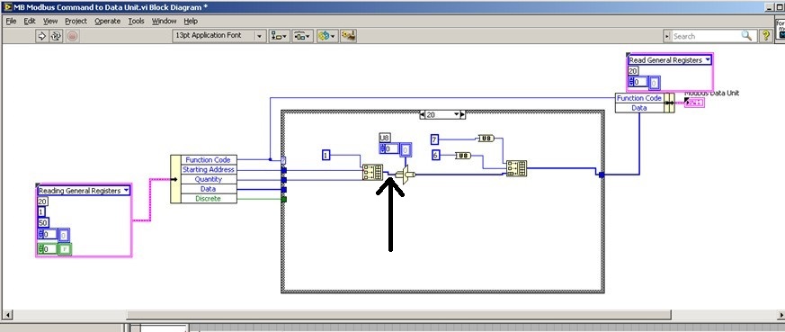
We try to add 20 saving file read function code in order to read the brief in bulk from PLC. We used the modbus for Labview library to communicate with the PLC with Modbus TCP/IP, but when I addes the code function 20 to the cluster of the MB Ethernet Master query entry reading registry Palette entry, the program displays an error. I'll be really appreciated if someone could help with this problem!
We hope all have a good weekend.
Best regards
Sophie
Actually... that is a constraint on the second entry to "build the table? ' It is difficult to tell from the image. If so, what is the data type of this cable?
That must be an array of U16s, because the "quantity" and "home address" are U16. However if the value '1' is a larger data type as U32, labview perhaps at upconversion of the whole table that would result in a larger data set than expected and could cause error 2. You can check on this?
-
invertek modbus communication by car
Hi all
Seems modbus is a way to communicate with the disks for a long time. For me, and because we have a new machine equipped invertel drive P2 is new.
So, after many emails between invertek I couldn't so much as to communicate with the reader with their software. Only her entry to go to modbus.org
For their software, I use a converter usb rs485 and I use pins 4 and 5 (pc connection), but for modbus change for 7 and 8 (modbus)
Join is the manual for modbus for the driver.
My question is, what is the easiest to read VI (for now) of records and the way to the entrance. I need to input 03 (for reading), then the registration number?
Please help for the first step, then I'll build the complete software (I have now installed modbus library)
Thanks in advance
cpalka
-
ComBox MODBUS - difficult to write in the registers of the S.R.I.W.
Hey guys,.
I'm talking to a UPS (ComBox XW +) via MODBUS TCP. I can read the values of read only registers very well, and they line up exactly what I see on the interface of the web page they have. However, when I try to write a particular register r/w, I get an error of the incompatibility of function (-538172 using modbus smithd API). Also, when I try to read the register R/W, I always get the value 65535. This leads me to believe there something wrong with my configuration of device, but just in case, I thought that I would make sure that I wasn't doing anything weird in the code. Please the the image of the block diagram, as well as the manual that I use for the device in the attachment.
There is a small note MODBUS online as well:
http://solar.Schneider-Electric.com/wp-content/uploads/2014/04/conext-TL-using-Modbus-application-No...Hey Thomas!
Thanks for your help, however, this link is not available more when I try to open it.
In any case, this problem is resolved. I was just writing the bad slave ID! The other slave was present on the network, but it is card MODBUS is completely different, that's why I was seeing these weird values.
-
How can I change the address Modbus to Modbus IO server programmatically?
Hi experts,
I use a cRIO 9076 that is configured as a server IO slave Modbus to Modbus TCP communication. I have always used the same Modbus address to configure the server of e/s and it has never been necessary to change so far. So I was wondering if there is a way to change address Modbus IO server programmatically, after it has been initially configured?
Thank you
Volker
Hi Volker,
There is an Express VI, that lets you create or change existing servers of e/s Modbus programmatically createand configure the Server IO. Once you set up like Modbus, you will be able to provide the address programmatically.
In regards to the address - you are right in that the Modbus address configured in the configuration of the server is not really used with Modbus Ethernet. According to Modbus specifications, the address is used when a network connecting Modbus Ethernet to a secondary network series Modbus via a bridge or a bridge. The specs say that the address 0xFF should be used on an Ethernet network. For more information on this topic, Please see page 23.
Hope that helps!
Best regards
-
Analog value read with DSC Module Modbus
Hi, I have a Delta PLC with an AD converter module. I use the four analog channels and in one of them, I have a thermocouple which displays temperature data on a microprocessor thermocouple meter. However, I want to display the data in Labview. The controller communicates with labview through the DSC Module of labview with success, but I am not able to read the data. Looking forward to your help.
Found the solution. addressing to the modbus master was different for this model of plc, so I looked up the address for delta plc Modbus and the analog read list has been a success on labview.
-
Power Meter Modbus rs485 via 9871
Hello
I'm under Labview 2015
I'm currently trying to connect has the place D Pm820 (meter) NI 9871 module in a crio 9076. The project is supposed to read the performance data in the registers of the meter (current, voltage, etc.) using the port rs485 on the back of the meter.
The pm820 has a pinout for rs485 2-wire with 1 (-) 2 (+) and a 3rd Armor/ground wire. The pm820 meter is a slave device that has several different protocols that it can run on (Modbus RTU/ACII8/7 and JBUS).
The setting of the counter are:
Protocol: Modbus RTU
Address: 1
Baud rate: 9600
Parity: None
I use the module 9871 for device communication for the cRio
I use the power cord that came with the module 9871 RJ50 to db9 and have the pins 4 and 8 rider (TXD + TXD +), and then connected to the (+) 5 and 9 meter jumper pins (-RXD, TXD) - and then wired to the (-) meter and ground on pin 1. I have read, it's how wire you the db9 connection rs485 2-wire.
My first goal is just to get the communication with the power meter so that the value that I see in the registry, it is what I should see.
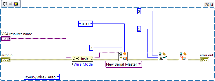
I started using an example VI for holding registers (master modbus on target RT) reading as labview was pre-constructed and changed it so that its contribution would be to port 1 on the 9871 as created controls for my run configuration. Other I left the rest of the VI that it has been opened.
When I run the VI I see numbers appear in the registry list, but they have nothing to do with the power meter. I unplugged the power meter and still got the same result however if you unplug the cable connection the 9871 1 VI will be a mistake (as expected). I have the feeling that the labview speaks to itself through the 9871, but I'm not sure. I looked at other posts, trying to find a solution and came across a mention of having to set the thread mode, but I can't find a way to do it using the modbus library. However I could not find an example reading VISA registers the using visa I see there is a way to do it.
I enclose a picture of my VI and the front panel to show what I mean.
If I could help either make my VI work or at least get pointed in the right direction that would be great. I'm not against the use of the Visa library either. Also if you have examples or resources that would allow that they would be greatly appreciated
It's just a part of my project but just get work communication is my main priority at the moment.
Thanks in advance,
Mike
-
Write to register using EITHER Modbus
OK, so this should be a pretty easy question, because I'm sure most of you have done this before. I need right in a register in a slave device modbus, I know the TCP/IP address and the register but I'm looking for help on how to write data to the registry. I guess most of which can be accomplished by the header, but I don't know how to handle the other header and reading of record keeping.
Thanks for the help,
Mark R.
Thanks to all who responded. There was an error in the manual for the device. It is said to communicate with the device on the port 50. I tried this several hours trying to figure why it was time to connect open so I changed to http by default 80 port since cheating on him could be accessed through a web browser. This changed my timeout of my write function error. Finally, I decided I would try the port of tcp/ip by default 502 as a last ditch. This seemed to solve my issues this project is finished and all communicate well.
Thank you
Mark R.
-
Closing datos por en scada modbus
Muy buen dia a todos.
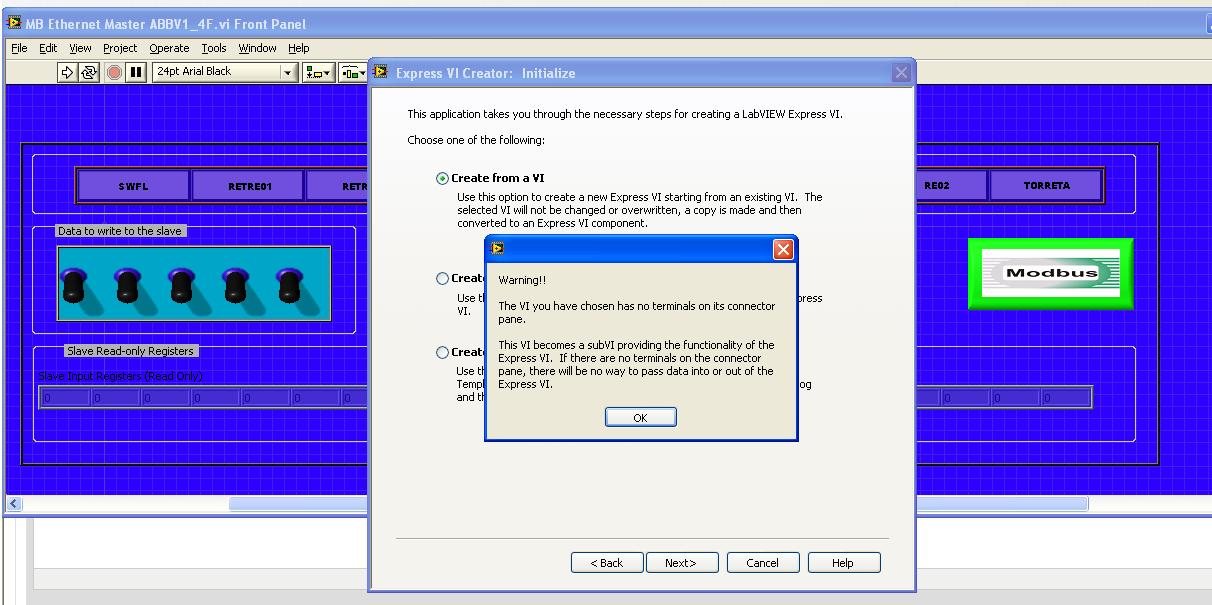
Estoy modificando UN SCADA in the empresa in donde trabajo pero el problema as hay are consta esta para trabajar con FIELDPOINTS, yo eliminate los fieldpoints u OPC powered through y con PLC of MODBUS TCPIP similarly o serial ABB. Comunicación is the prevalence, puedo leer y señales analogicas write y digitales pero el escollo librar trato're como VI individual intensification has the perfeccion, pero ago al of integrarlo hora of SCADA no works, me errores marca el as como modulo escritura y lectura modbus esta receiving characters no aceptados o things asi extranas, estos momentos estoy tratando crear a Subvi don't express pero no is como hacerlo , is that the of primero doy a tools y ahi in crear una nueva express vi, of doy NEW despues en CREATE from a VI selecciono mi VI y me appears lo siguiente:
SE me hace porque mi vi tiene tickets extraño y salidas, in this case tickets las salidas St o o reels pero no be that pasa.
También estoy intentando hacer algo con las share if is you can hacer algo pero tampoco, en so mi problema're than mi SCADA y MODBUS corran al mismo tiempo, tambien initiates include todo el vi in SCADA el plano y cuando llega el programa ahi flow to para todo, ahi is is, variables, supuse than era una structure while , is the altogether there are quick-witted pero solo is me da UN valor.
Ojala me can help alguien esto is to give has a client unos dias UN y todo esta por eso paradox.
Mucho thank knew tiempo, reciban a cordial saludo.
ING. A. Abraham. Alfonseca Melendez
Normal
0fake
fake
fakeEN-US
X NONE
X NONEMicrosoftInternetExplorer4
/ * Style definitions * /.
table. MsoNormalTable
{mso-style-name: "Table Normal";}
MSO-knew-rowband-size: 0;
MSO-knew-colband-size: 0;
MSO-style - noshow:yes;
MSO-style-priority: 99;
MSO-style - qformat:yes;
"mso-style-parent:" ";" "
MSO-padding-alt: 0 to 5.4pt 0 to 5.4pt;
MSO-para-margin-top: 0;
MSO-para-margin-right: 0;
MSO-para-margin-bottom: 10.0pt;
MSO-para-margin-left: 0;
line-height: 115%;
MSO-pagination: widow-orphan;
font-size: 11.0pt;
font family: 'Calibri', 'sans-serif ';
MSO-ascii-font-family: Calibri;
MSO-ascii-theme-make: minor-latin;
mso-fareast-font-family: "Times New Roman";
mso-fareast-theme-make: minor-fareast.
MSO-hansi-font-family: Calibri;
MSO-hansi-theme-make: minor-latin ;}Hola Abraham, the advantage of
comunicarte con directly los lugar por MODBUS FielPoints are that the communication
haces el through pilot directly variables compartidas, ahora o
con estos tambien you puedes Comunicar por MODBUS. Para con MODBUS communication
Server i/o MODBUS to estas using el este esta LabVIEW RT o en LabVIEW DSC, o
the MODBUS libreria utilizando estas. ?Ahora el error that you
Genera el del VI Express are you porque VI not las tiene nada en contacts
Terminal, an esto is refiere don't con as no tickets tiene y salidas. Ahora
probably aqui no using screw Express, the utility of los need live
Express General are building as despues con use en herramientas para
Los programas mas than fr if a component in a specific en programa, y proven
MAS well utility para el Worflow para el programa final.Ahora el problema aqui of
No funcionen juntos can be much more than a problem of integration. Como so
mencionas you colocas a Subvi, con a ciclo while inside of a VI, VI el
main goes a detenido meet (o por lo menos el ciclo in el as metiste
Este Subvi) terminen run one until. Quitar el ciclo Al solo everything is
runs una vez cada vez lo controls has call desde el principal, so solo lo
Mandas call una vez solo you will a dar UN dato.Ahora lo mas algo
con el to use are simple as puedes hacer I/O Server in case of than cuentes
El, there is what sets el I/O server variable ligar puedes compartidas has los
looking for MODBUS, y como utilizarlos compartidas variables in you sistema
SCADA.Estas ligas you pueden ser
utility of:Connected LabVIEW has any red Industrial y PLC.
Developer Zone - National InstrumentsHow to turn an RT target in Modbus slave using i/o
Servers - Developer Zone - National InstrumentsConnected LabVIEW has any red Industrial y PLC.
Developer Zone - National InstrumentsSaludos
-
How to connect Labview to PLC Modicon Quantum (140 CPU 311 10) with Modbus
I was wondering if someone could give some tips on how to connect Labview to Modicon Quantum plc (the card is 140 CPU 10 311). I am eager to serve a Labview HMI to control the controller that is used to implement the control PID with a VFD. Currently I can communicate via Modbus to the API for programming using UnityPro XL, but I have no idea how to connect Labview. I read the article on place OR "connect Labview to any PLC via Modbus", but I don't know yet. Any help will be greatly appreciated.
Hey Greener.
Communicate with the PLC via Modbus usually requires the Datalogging and Supervisory Control (DSC) Module to have this feature available in LabVIEW. The white paper which indicated you using this module, which may explain why you can't get the communication at work. If this is something you don't have, and purchasing a license is not an option, then you might be able to use Modbus unofficial libraries to get the functionality you need. I have included a link below to a Modbus for LabVIEW library that you can try.
DSC module:
http://sine.NI.com/NIPs/CDs/view/p/lang/en/NID/209851
Modbus Library:
http://www.NI.com/example/29756/en/
Kind regards
Ryan
-
Deal with failure when using LabVIEW 2011 and DSC MODBUS communication
I'm currently reading from operating records a PLC with MODBUS/TCP. I confirmed that the PLC will update the values and in response to a MODBUS communication correctly by using a third-party program called Modbus Poll. However, when I try to query the PLC using the LabVIEW shared variable engine, I am unable to read the values of the same addresses that I consult with Modbus Poll.
My installation is simply to a PC directly connected to the controller via Ethernet without a router between the two. I'm using LabVIEW 2011 SP1 with the DSC module.
I opened the Manager of distributed systems OR to display the State of all variables in the Modbus Library that I created, and I noticed that the ILO CommFail permanently the value 'true '. All other variables with a 'read' access mode signal "failure of process". I tried to restart the process and stop and start the local variable engine without success. I also restarted my computer several times to see if any services did not exist, but this does not appear to have solved the problem.
Finally, I resorted to listening to communications on the network card I have the PLC connected via Ethernet using Wireshark and found that while Modbus Poll communicates with PLC, number of MODBUS and TCP packet is sent and received. However, when using only LabVIEW or the DSM OR communicate with the controller, there don't seem to be any communication on the network card.
Something that may be interesting to note is that I could communicate with the PLC and to read values with the DSM just once, when I understood everything first what address I should be reading of. All of this has stopped working shortly after. Prior to this, 'CommFail' was not generally set to 'true' with my current setup. Thinking it was my firewall, I have since disabled my firewall, but this seems to have had no effect on the problem either.
Any help on this would be appreciated.
So, I thought about it. It turns out that the IP address of the server i/o MODBUS must be set to the address of the MODBUS slave, not the local computer. The address of the i/o MODBUS server is defined by the navigation in the Explorer window projects, expanding the variable engine shared library for MODBUS and right click on the server MODBUS (for example Modbus1) item and select Properties.
In addition, the addresses seem to be shifted by + 1.
Thanks for the tip so.
-
Cannot write negative values on server modbus on cRIO 9068
Hello everyone,
I'm moving a project from a platform of 9114 cRIO a cRIO9068, the reason for a difference of heavy in terms of power CPU, memory, performance FPGA etc...
Real time I deploy a modbus TCP server, and I publish just I16 data.
The problem comes when the program tries to write a negative value to a binded on modbus variable. This variable is in the same format (I16), the program could write negative values, between 0 and -32768, but whenever the modbus force set to zero.
I tested the modbus also with the 'system of distributed OR 2014 Manager' but always impossible to write negative values on I16, but I can if I consider the data as I32!
(see files)
Furthermore, I deployed a modbus server on my PC and in this case, everything is fine.
More information:
I work with labView 14.0f1.
The cRIO are installed 'Labview RealTIme 14.0.0' and 'server Modbus I/O 14.0.0.
I tested the feature on three different cRIO 9068 with the same result.
I think it's something wrong with cRIO 9068, can anyone help me?
Thank you
MZ
Hi, Marcello,.
I was able to reproduce the problem cRIO 9068 and it look like a CAR (corrective action request). I've opened a request for Corrective Action (AUTO ID 511039) to report the issue OR R & D.
Have you tried to implement MODBUS slave on ana MODBUS master PC on cRIO? I tried and it works even with I16 data types.
I hope this will help you.
Kind regards.
Claudio Cupini
OR ITALY
Technical support
Maybe you are looking for
-
Cannot receive the Vista SP1 via Windows update
Hmm... O always waiting for SP1 update through WU. I am at a loss of what kind of drivers that may be causing this not be available. Anyone have any ideas? I know that I've posted about this before and others have said to download the standalone vers
-
Keyboard on Satellite A200 problem
Hi, while hoping a bit of insight into what the problem may be with my Satellite A200. It started with one single key works does not, then one other has stopped working. Then I would press a key, but it would come with a different letter on the scree
-
HP Pavilion 15-n220ca drivers windos 7
I hate windows 8, I have install windows 7 64 bit on my computer no UN HP Pavilion 15-n220ca, I can't seem to find drivers on the HP site can someone me rescuer pour find drivers for windows 7 64 bit
-
Use screws of no class within the class
I guess that it is a theory of the question of the OBJECT-oriented programming. Say that I have 2 classes, 1 is used to adjust the tension on a diet and another is used to update a user interface. They are not really related to all that there is no
-
DirectX 11 accidents of Battle Field Bad Company 2.
Original title: looks that directx 11 are causing problems for my system. My current setup is Core i5 750 ASUS p55 mobo 4 GB of ddr3 memory OCZ ssd GTS 250 1 GB After freshly installed Windows 7 Professional, I installed Battle Field Bad Company 2 of