frequency of the digital signal 6009
Hello, how to generate the digital signal with frequency 50 Hz using NI USB-6009?
You can take a look at this:
Can I use a generation of impulses with the counters on the USB-6008/6009 case?
Tags: NI Hardware
Similar Questions
-
time extraction of the digital signal
Hello
If I have digital signals from optical barriers and to extract the time (for a body that passes these 2 obstacles) how can I retrieve this day there using Labview.
THX
I have chata,
Thanks for the answer, and I hope that your well.
Here's an example I've done for a client, eager to discover the time of a flat section of its waveform.
In your case, you must make a detection of pic on both codes, then less locations and a few x with the number of the sample to get the time.
Let me know what you think.
Kind regards
James.
PS Sorry code is a bit hasty.
-
6008 USB shows the digital signal with nothing plugged
So I really hope that's not too bad, I guess it is.
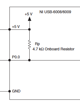
I had problems reading of my digital USB 6008 entry this morning. Everything worked very well last night. Now all digital lines on the device to read a signal if it is has that anything connected to them or not. When I run the DAQ Assistant and test line, it shows a signal to each line. Then I did the joint VI (which should do the same) and it shows a constant signal in each line also. And I have nothing connected to the unit. Should reset somehow, or it is broken? Or am I just missing something?
nckeeley,
Look at pages 21 and 22 of the User Guide Ni USB-6008/6009 and specifications. Digital lines have a traction 4.7 kilohm place resistance to + 5 V. It will be a line of input opne look (and be) high.
Lynn
-
Could someone tell me how to convert the digital signals in table 1 d of digital waveforms
I use 9474 for drving an engine. for that I have uses 2 ports - to activate and another for running. These signals in the form of Boolean values. I am to convert these signals to a table and since iam doing a digital waveform. but when iam connecting these to the module 9474, it show an error "source is a digital waveform and sink is 1-d array of digital waveform... any body can help in these issueee please...»
Pop - up on the thread and choose Insert...
Build the table.
Ben
-
NEITHER USB 4432 readable voltage i.e. the ASPM signal conditioning
Hello
For what I understood that the USB-4432 entries must read IEPE accelerometers report. Read a voltage signal conditioner of my sensor ASPM IE using the option 'IEPE-off with AC coupling.
Thank you
1. What if I use the 5th cahannel of
4432 read the square wave pulse width, i.e. the digital signal
tachometer using any function of sounds or labview software and
Vibration Measurement Suite. If so, how precis specific will be read
frequency (speed) compared to meter modules.Channel 5 is the same as the other channels of the 4432 except it lacks excitement IEPE and TEDS. I can't really say how "accurate", it will be at a faster rate because of the delta-sigma ADC. Someone else wants to chime in on this one?
2.
Is available to trigger analog acquisition of digital triggering. If so, is
It possibel to read all 5 channels togather in a single task.You're talking about!
3.
If there is only one PFI then is possible to trigger two
different tasks, i.e. a task of 02 strings with front amount and
a further task of 02 channels with the falling edge of the PFI even.There are 8 PFI lines, but can only be used on the device at the same time (it might as well be one PFI). You must have all the channels you want to raise in a task and use one as the trigger for starting digital PFI lines. (i.e. 'no'
 ... have a stain on the front and the other on the falling edge won't work, a task only by digital triggering)
Germano-
-
analog sync of input with the onset of the digital output
I'm trying out an analog signal to a file with a specified frequency samples. I also need a digital output to trigger a measurement at a frequency specified on a separate system. The frequency is controlled by the loop exits and timed when the iteration number divided by the period is exactly a whole number.
Both outputs work. The problem is that they are not synchronized. The analog output amounts to about 0.5 ms faster than the digital signal. (I checked with an oscilloscope) They both start in the 1 ms each loop runs for, but I really need them to start at the same instant. What can I do to synchronize? Also, if I'm going in the wrong direction complete, please indicate.
I use a card PCI-6723, which I think someone at some point, said not having a material sample clock. That's why I try to use a timed software loop.
Hi NEA.
You must use the 6723's built-in calendar to accomplish what you want. As the digital output subsystem is only clocked by the software, an appropriate solution should be to use one of the counters to the pulse output.
The attached code should show how. You can use the counter to output a pulse all samples of the AO N task. Material requires the initial delay to have a minimum of 2 ticks, so the meter will be behind the task of the AO by 2 samples in this case. There are different ways to work around this problem if you need (for example write two samples of 0 first).
Best regards
-
Capture of frequency with the NI 9401 in cDAQ-9172
Hi all
I searched through all the examples and find the same results than my own code in Labview. So, I go back to my hardware to solve my problem. I use a digital tachometer that displays pulse with 2 wires (hot and ground). I connected these to the NI 9401 for 16 PINS for PFI 1 and PIN 3 on the ground. When I open the module through MAX, he reads the perfectly when hi and lo as well as count properly if it is placed in the location 5 or 6.
However, I try to use the frequency max task and the task fails to capture anything in the table. I get a time-out error, even if my tach is read correctly. I have attached my settings of the task. Thanks for any help
Your samples to read is set to 100. If all the samples of 100 are not available before the timeout is reached, you will get a time-out error. What is the frequency of the input signal? Maybe just try to read 1 sample on request first.
Best regards
-
PCI6120-acquire an analogue signal on each edge of a digital signal
Hello
I have the card PCI-6120 and Labview 7.1.
I have a digital signal of the encoder. Am interested in buying an analog voltage on each rising edge of the digital signal. In addition, I have another digital signal (index) between which I wish to make the acquisition.
I tried several options. But I can't get on the digital dashboard via the hardware. Please help urgently. Alternative, I migrated to the acquisitions acquisition high speed analog and two digital channels and deteting change in software programming and then find the analog voltage. Which is heavy and inefficient.
Kindly guide correct programming technique.
Concerning
Marie-Hélène
Hi, Maud.
Thanks for the update and I hope that your well today.
Sorry for the delay but it was the Easter holidays!
Thank you for your congratulations.
I put your sampling frequency at the maximum rate of the clock source (encoder). The DAQmx driver uses the sampling frequency (and the number of samples per channel) information to perform various calculations and set sizes for the buffer.
If you set it too high, nothing will happen-guests still just on each edge of the unit receive. If you set it too low, your stamp could be too small and you may lose data.
Hope this helps,
-
MyDAQ - generation of a digital signal and display on an analog waveform graph
Hello
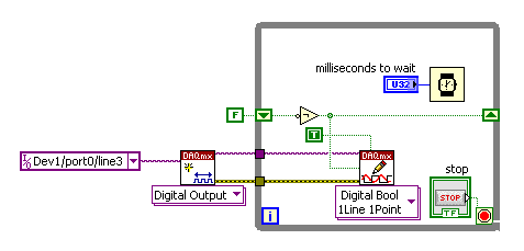
I use the MyDAQ OR generate a digital waveform with a Frequency adjustable. This is implemented in a program, I already wrote it, which generates a TTL 'like' impulse out of the sound card. I display the result on a graph of analog wave form, and I would like to be able to display the digital signals generated by the myDAQ on the same graph. (Not in the same time, one or the other, activated by a button). I've been messing around with tables and conversions, but I can't really do with all this.
It's the vi, I did to generate the digital signal of frequency with MyDAQ. Any suggestions on how to do this if the following is false, would be great too, as I just got the MyDAQ a few days ago. I think there must be a better way, but it's the best I could come up with so far.
Hi Jonny,
The General logic, that you use to create a digital pulse train is very good. This VI you wrote should work and create the pulse train based on timing of software (which is fine because you have not DIO clocked by the material on the myDAQ anyway). However, it is generally advised to start the DAQmx task just before your time loop and then disable the task after the while loop when you press stop.
For reference, there are a few examples of good enough LV that I recommend you watch too much for this application. If you try just to create a digital pulse train, the example Gen dig Pulse Train - Continuous.vi is a good example that uses a counter to create a digital pulse of your desired frequency train. It is generally the preferred method to create a pulse train, if you have equipment available to do (the myDAQ there a meter). Otherwise, there are a few examples DIO who write continuously in a digital line / port.
If you are unfamiliar, you can find the examples by clicking Help > examples find... into LV then navigate to hardware input and output > DAQmx > generating digital impulses or the digital generation.
Also, here is some additional information on the myDAQ and its counters:
Hope this helps.
Chris G
-
I would like to create a digital waveform as instructions for a stepper motor. The task is to get the motor shaft turn at variable speed within each rotation. I tried to do this by dividing the rotation in a number of blocks that each run at a different speed, thus forming the concatenated rotation profile.
The problem is that then the concatenation of the digital signals with the Append VI, I am unable to remember the different frequencies of the individual wave since the Append VI seem to require a constant interval between two pulses. Is it possible to explicitly concatenate accurate digital waveforms to form the desired profile?
Try again with the modified VI.
-
How to convert an analog signal into digital signal
Hello
How to convert an analog signal into digital signal, such that each sample of the analogue signal corresponding to 1.2V will be represented as '1' digital signal and other samples of the analog signal (which are not 1.2V) will be represented (converted) ' 0' in the digital signal.
And how to view the wavefroms or graphical indicators signals.
Thank you.
If you have 1000 samples and you want to convert to digital, you get 1000 digital values. Attached, that's what I mean.
-
Cannot receive digital signals through Media Center after local supplier upgrading to digital cable
I hope someone can help.
Dell XPS computer
Windows Vista 32-bit
ATI Theater 650 Pro TV tuner
Recent upgrade of our cable system has left me without all the digital signals being recognized by Windows Media Center. Have still 13 first typical analog signals. I tried everything to get digital. Here, they are identified as XX - 1. Apparenty the TV Pack Upgrade will solve the problem, but I can't seem to download right from my computer (or at all). Any ideas.
-
Reduce the period of sampling of the digital inputs of NOR-USB-6009
Hello
I need to read a line of digital input in the NI USB-6009 using NOR Express 2013 Signal box. I selected 1 sample (upon request) as acquisition mode. I need to define a smaller sampling period as 1 MS, but it gives error too short sampling period: "the current sampling period is too short. Please specify a longer sampling period. ».
I do not understand the reason for it and a way to slove this.Any help would be greatly appreciated!
Thank you!!
The 6009 doesn't have a clock that you can set for a sampling period. According to the specifications, the digital I/o is software programmed - sample on request you use now. I'm not at all familiar with SignalExpress but I don't think that you can find near a reliable khz sampling frequency on Windows or any other os non-deterministic.
-
VI to convert input signals NI 9402 in a RPM value, based on the frequency of the pulses
Hello
I'm looking for a VI convert an input signal NI 9402 in a RPM value, based on the frequency of the pulses. Is there such a thing that exists in the library of national instruments?
I run LAbview 2014 integrated control and monitoring on on a cRIO 9802 high performance integrated system with NEITHER 9402, 4 channels, 50 LV, LV TTL Module input/output digital, ultra high speed digital i/o for the cRIO module.
Any help would be greatly appreciated.
The easiest way is to use the FPGA to get the time between the edges of your pulse increase (shift registers to maintain the current situation and the time will be necessary). This will give you the period. If it's a single pulse per turn, then the number of laps is just 60/T, where T is the time in seconds.
-
How to measure the digital output of the linear actuator on USB-6009?
Hello
I am a new user of Labview and need help to measure a digital input signal.
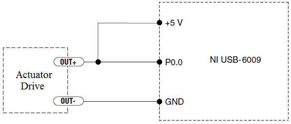
I have an actuator Bimba Original line electric with a motor continuous integrated with encoder, drive and the controller. The drive has a programmable digital output that I put as a tachometer output that emits pulses of square wave 100 per turn of the engine. I put the engine to make a total of 56 rev in 22 dry. I want to measure the speed of motor rotation labview real-time and synchronize it with a few other analog input signals. I wired the actuator for the USB-6009 case as shown below.
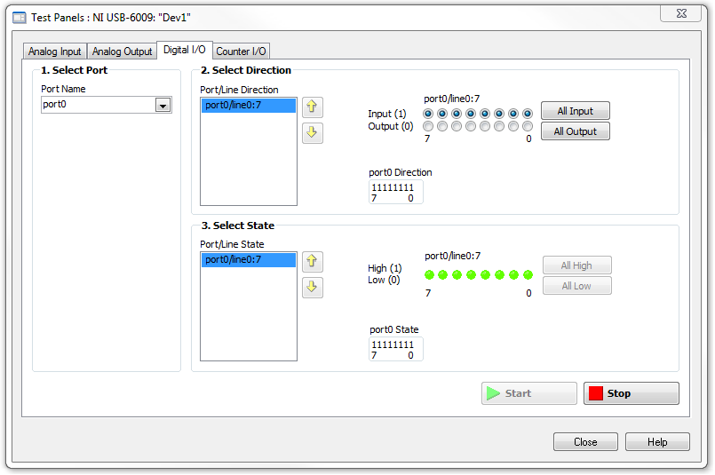
I opened the test i/o digital USB-6009 Panel and fix all the lines of port 0 as inputs. However, when I click on start and run the actuator, p0.0 led flashes, as indicated below.
Shouldn't the led blink in response to revolutions of engines?
I want basically to collect the drive pulse signals and convert them in rpm on labview.
ahsan2 wrote:
I have it wired correctly?
It would help if you do not attach the HIGH signal. Remove the + 5V in the circuit.
Maybe you are looking for
-
Is iCloud photo one 'off site' upward?
While I use a backup device for time machine (airport Time Capsule), this device is in my house and my Mac... I also have and use iCloud photo. Is iCloud photo a "off site backup" in case my Mac and airport Time Capsule are lost in say a fire in my h
-
What is the best for VMware esx 4.0
If I understand correctly, 4.2.1 for windows only supports VMware esx 3.0? IF ACS 5.0 supports VMware esx 4.0? Or is it a solution Manually applciation compete with hardware? Pls help?
-
Limitations associated with connection tables to UCS FIs live.
I understand that to connect directly a table of UCS, the FIs have put (NPIV) mode of the switch. But once you are the FI in Switch Mode, it is impossible to join other SAN switches in the fabric interconnects? It is my understanding that you could
-
No way to stop an Animate scroll in Muse, when she reached the end of the scenario main animate?
-
How this function runs? When I write below the rule... the person meets the condition of age if both TemporalBefore(2007-01-01) and age in years > = 55 or both TemporalOnOrAfter(2007-01-01) and age in years > = 65 How this function evaluates the conc