NI 9514 free servo control jig
Hi, I have a Question because I still don't understand something on my program. First I use a cRIO 9022 and a NI 9514 module with an analog servo AKD drive to control my engine. I already have one using VI scan mode interface and the SoftMotion function blocks and it works OK. The problem is that, from what I understand, this scan mode uses the scan engine clock, where the minimum of research is period 5 ms. I'm running my engine between 500 and 2000 rpm and the "only" thing that I need is to send a signal of TTL output to a given position that I use as a control variable. (I use a NI 9401 for this attached to the block function Position compare). As I said, it works but not very accurate and there are only 2 options, either the control loop is too slow, or it has jitter in the other system I use (I can take images of the rotor and see with precision the angle and 1 or 2 degrees is a big mistake for me, which means that only 0.5 ms in time If I use 720 rpm for example. I'm now 5 to 6 degrees of error).
If my order is the problem, how can I make sure it's the VI the problem and can I do to fix this? I read here http://forums.ni.com/t5/LabVIEW/NI-9514-FPGA-and-SoftMotion/m-p/2173030#M699003 even if I use FPGA with my NI 9514 I still cannot remove the scan engine.
Thank you very much!
Italo
Hi Italo,
Here are some answers to your questions:
-If you can access the PIN Position compare, then you should be fine without the hardware connector that I mentioned in my previous post.
-The exit of the hairpin to compare position is a TTL signal 5V that you can access and use as your digital triggering. This will eventually cause at a pace much more reliable that the digital triggering generated you through the 9401 using the analytical engine.
-Your scanning interface program should continue to work properly. The program that you are using is able to drive the motor at the rate you were hoping for, the only problem is that we are relying on the analytical engine for digital triggering on the 9401, which does not give you the resolution of trigger, you needed. Using the PIN Position compare since the 9514 addresses this concern for us.
Tags: NI Hardware
Similar Questions
-
I'm pulling my hair out here... I hope someone can help to guide me in the right direction. I'm just learning binary and hex, so please forgive me (and correct me!) if I say something wrong. I have to give credit when it is deserved, because I use info from a post on theautochannel.com to drive this development.
I try to control a small indoor RC helicopter using LabVIEW and a USB joystick. I communicate with a transmitter wireless via rs232 (TTL converted), the Protocol is 125000, 8n1. Each image is 14 bytes 2 bytes of header. I would like to transmit data PPM (pulse position modulation) which is actually just a 10bits (1024 possible measures) range that dictates the position of the servo, for each channel.
Byte 3 & 4 are channel 1, byte 5 and 6 are channels 2, 7 & 8 CH 3,... and so on until the bytes 13 & 14 which is CH 6.
Each pair of bytes begins with "00" (binary).
Byte 3 & 4 should look like "00 00 00 xx xx xx xx xx", where the first "00" is the header, then "00 00" is the identifier of the servo, and 'xx xx xx xx xx' represents the position of the servo. The identifier is actually integrated in the position of the servo, the bits serve a double purpose.
That's why it all will look like this:
CH 01:00 00 00 xx xx xx xx xx (position has a valid range from 0 - 1023)
CH 02:00 00 01 xx xx xx xx xx (range 1024-2047)
CH 03:00 00 10 xx xx xx xx xx (range 2048-3071)
etc... If you convert the binary range, you can see how the second half of the bits ID servo are provided by the range of servo.
I intend by entry VISA to send every byte to constitute the entire frame, and then I will pause ~ 10ms between frames. However, my question is how the hell should I code this? !! I think I need to write, take 1 CH for example, bytes 3 and 4 together into a string and then split them back hand to be sent as two distinct bytes. However, I do not know how to mix my header and the first two bits of my ID servo, which is binary '00 xx', with my servo position (which I know I can write in decimal form, as entry VISA will convert it in binary). Any thoughts on the best way to do so, given all this?
An empty string character likens to a binary "0"?
Has totally confused everyone? I really hope not, but I'm pretty tired so let me know if I need to simplify my question. I hope someone can enlighten me as to the best way to combine the binary constant w modification of decimals (or hex). And if anyone has thoughts about a good way to organize my vi together, I understand that too! Right now I'll just use the structures of sequence... I post my code but at the moment, there is not much to look at
Thank you very much!!
No, you do not confuse everyone, but I think you might have confused yourself.

You basically need to do is to create the array of bytes that will be sent, and then use the array of bytes to a string, so you can send it to the serial port. The creation of the byte array can be done in several ways. You deal with 6 16-bit numbers, of which the lower 10 bits are the values of the position of the servo. I don't know what you want on the front panel to look like, but if you have 6 separate (one for each servo) controls with each set having a range of 0 to 1023 (for 10-bit), then you just have to OR each value based on the number of servo. Put all this in a table, add the bytes of the header and the array of bytes to a string allows to get a string that you can send via the serial port. You can also do this in a loop. Joined a VI to show the two concepts. You have not indicated what version of LabVIEW, is 8.2 you use.
-
Resampling in the free transform control
When I take pictures on internet to change or use em for the inspiration, I often need to resize them. Using Image > Image tool size work if I have the image I'm resizing in a separate window.
Then I can choose resampling: Bicubic Sharper. However using the tool free to reduce processing an image gives me none this option, causing the image degrade in quality over the free transform.
Is anyway to resampling for free transformation?
the free transform command uses the default resampling method defined in the general section of the preferences
-
DC motor control - axis of movement back
Hi all
I am currently (trying) to design a control of a servomotor system.
I use a cRIO 9082, NI 9514 C-module, a servo-drive Kollmorgen AKD and a Kollmorgen servo.
My main goal is to make the engine during continuous running + 15 deg to-15 degrees and with varying frequencies.
I checked my system using the 'straight axis' operation - example, that comes with LabVIEW.
How do I start making a model more sophisticated movement?
I modeled the DC motor in MatLAB using PID control. I can do something similar in LabVIEW?
See the image as an attachment to the model of behavior, that I want to accomplish.
Thanks in advance.
Best regards
JZaulich.
Hi JZaulich
You will need to use the NI Control Design and Simulation module to perform the simulation and model of different systems.
http://sine.NI.com/NIPs/CDs/view/p/lang/da/NID/209850
If you install this kit there are a good example called "DC speed control Cascade" engine that can show you how to model the motor and continuous control (both speed and current ". There are also examples of servo control.
Best regards
Anders Rohde
-
Custom control with couple or the input voltage system
Hello
I'm relatively new to LabVIEW and this is the first time that I'll use for an application of movement. I have a controller/chassis cRIO-9074 with a few modules NI 9514 IO, servo motors and drives, and I'm trying to do is to use a custom control in my system (a sliding mode control law) to generate the signal for the movement of the engines. I was able to produce a movement OR softmotion but so far I've been able to produce with position, speed and acceleration as inputs and to optimize PID gains. What I want to do is to send commands to torque or tension from the entrance of my right to command control is torque for motors. What I was wondering is if it's possible with the components that I use now and if someone could direct me to useful articles or books that can help me.
Sorry if is a noobie question but I only worked theoretically with systems of control far and I didn't simulate the results with matlab before that. It is the first time that I had to get the experimental results to validate my proposed control right. Thanks in advance.
Hi,.
This may be possible, but since sending the commands of torque or tension directly don't are not supported in scan mode, you can use your 9514 FPGA mode.
This link describes the components needed to run the FPGA device.
You should be able to find examples in the Finder for example NEITHER, but here is an overview of the use of FPGA that can be useful as well.
-
Servo motor RC directly from sbRIO e/s digital
Hello
I would use a Committee sbRIO to fly a RC servo.
A RC servo control is usually reading a signal modulated TTL level pulse width.
Calendar will be no problem in using a sbRIO, for the FPGA can manage that.
But I am concerned about the level of output voltage of the output digital sbRIO; High level, it is specified as being > 2, 7V (max 3, 3V). It seems to be ok with the high level of TTL level requirement, but I wonder if anyone has tried this.
Thank you very much for comment, that you will have on this subject.
Tony
Hi Tony,.
http://digital.NI.com/public.nsf/allkb/ACB4BD7550C4374C86256BFB0067A4BD
This is compatible with TTL.
Kind regards
Bottom
-
Hello.
I need to educate yourself on the hydraulic servo control with Labview. I have the card DAQ 6024. Can I control the servo-valve with 6024 map and Labview 6.1 and also for the position of the hydraulic cylinder, I will use a lineer potantiomater.
For example I thank you for your advise...
Hello
The 6024 will be able to send and read voltage signals, but you will need to implement the control algorithm in LabVIEW. There is no specific toolkit or a set of functions that NEITHER offer hydraulically controlled. If you have design control tools, you should be able to use it to implement some control algorithms. This application of closed-loop speed will depend largely on the PC that you run it like any process consuming RAM on this PC. Please send any specific questions that you have implemented your control application.
-
I need to set up a login for my older daughter of 5 years on our computer, so she only has access to Mozilla, and once on Mozilla that she cannot access inappropriate Web sites. Is there a step by step guide for someone who has never done this before?
My operating system is Windows 7
Thank you very much for you help and guidance.
Respectfully,.
Derek Mr. Bond
Hello Derek,
I understand that you're concerned about your daughter and there is certainly a way to solve this problem.1) http://www.qustodio.com/
This is a free parental control software that offers what you need(2) otherwise, you can also try this one: http://www1.k9webprotection.com/
Best regards, G-Cloud.
-
Unable to start by Satellite 5105 from recovery CD
Family XP Edition using
The original error was reading disc error, I used the recovery CD and the system started. I tried to use the installation disk of scan and the machine would not pass the free space controls 5% verified.
He then gave error reading disc once again, now for about 8 hours, that he sat to erase all the data of the hard disk 1.
I realize I could have to repalce the HDD, but just turn off the machine or y at - it some special way to leave this?
Thank youHi Lisa,
From what you say it sounds as if your hard drive is certainly u/s, so there is no point in allowing the CHKDSK to continue further. I think that you need to replace the hard drive (or have an ASP to do for you if you prefer) and then reinstall your system from the recovery CD.
Kind regards
-
Block a website using Firefox?
I want to block certain websites to prevent my children to have access to them because they contained porn and gambling
Firefox has no possibility of Embedment for blocking sites.
A few options for you.
- Install the add-on to FoxFilter, the disadvantage is that add-ons are fairly easy to get around - https://addons.mozilla.org/firefox/addon/foxfilter/
- An another add-on that can filter content is the ProCon Latte Content Filter - https://addons.mozilla.org/firefox/addon/procon-latte/
- Install a free parental control 3rd party as the K9 web protection - program http://www.k9webprotection.com/
- Use the OpenDNS service, there is a free version, and with it, you can filter the content on the categories that you choose - http://www.opendns.com/
-
Qosmio X 70-A - performance cooling fans
I can say with joy that this laptop is very well done and to make happiness perfectly but it would be very nice if you could either give free fan control or correct.
Laptop computer quickly becomes too hot and this would be fine if it could be refined a bit so that 60 degrees would be almost fan begins to rotate faster and 70 degrees completely fast.
The fan gets only at full steam 90 degrees which is abnormal and I think that this could lead to damage part
Message has been modified: translation has been added
Each laptop model has some cooling system designed for the hardware platform of the laptop and it is tested, so I think there is no reason to panic.
Is that Qosmio laptops have the best material on the inside so it is possible that the system is set to cool with the performance of the fans more.I don't know what objectives do you need your Qosmio, but if use you it for daily activities such as internet office and write emails, you can use the power saver power plan and change advanced power settings. I think that this will reduce the cooling fan activity and your laptop runs much quieter.
-
Drivers Windows XP for Satellite L650 - 1 M 6 installation sequence
Hello!
I bought laptop Satellite L650 - 1 M 6, but without an operating system installed.
Then I installed Windows XP.
But I do not know the sequence of CORRECT installation of Windows XP for Satellite L650 - 1 M 6 drivers.
The drivers have been downloaded here
http://ru.computers.Toshiba-Europe.com/innovation/generic/SUPPORT_PORTAL/QUESTION: What is the CORRECT SEQUENCE to install the drivers for Windows XP on the laptop Satellite L650 - 1 M 6?
Thanks to adnance!
The downloaded drivers are:
(1) assist
(2) update the BIOS
(3) Bluetooth Monitor
(4) Bluetooth stack
(5) Bulletin Board of
(6) assistant Bulletin Board of
(7) card reader controller
(8) utility, ChipSet
(9) Sales Manager
(10) common module
(11) Config Free
(12) controls of
(13) display driver
(14) DVD player
(15) Eco Utility
(16) facial recognition
(17) hardware configuration
(18) HDD Protection Utility
(19) AlertUtility SSD HARD drive
(20) Hotkey Utility
(21) EngineInterface of Intel management
(22) driver LAN
(23) Media Controller
(24) Media controller Plug-ln
(25) modem driver
(26) device registry tool network ID
(27) information product online
(28) PC Diagnostic tool
(29) PC Health Monitor
(30) play Ready PC Runtime
(31) power Saver
(32) rapid Storage Technology driver
(33) patch recovery
(34) real time
(35) registry patch
(36) gas station of
(37) smooth view
(38) sound Driver
(39) supervisor password utility
(40) TEMPRO
(41) touch Pad Driver
(42) start-stop of touchpad utility
(43) the mode technology
(44) public services
(45) value Added Package
(46) Webcam driver
(47) Lan Wireless driverHello
Order to install right WXP for your laptop model is as follows:
Windows XP Sp3
Synaptics Touch Pad Driver 15.0.8.1
Realtek 6.1.7600.30111 card reader
SW 9.1.1.1024 Chipset installation utility
Intel Management Engine Interface 6.0.30.1203
Driver Intel Rapid Storage Technology 9.5.7.1002
Display driver
Driver Intel Turbo Boost Technology 1.1.1.1007
Conexant Audio Driver 3.80.0.0
ATI HDMI Audio Driver 5.18.0.5502
Atheros LAN Driver 1.0.0.36
Battery Bluetooth for Windows by Toshiba v7.10.12 (T)
TOSHIBA Software Modem 2.1.77 (SM2177ALD07)
Conexant 7.80.2.0 Modem driver
Wireless LAN driver
ConfigFree 5.90.18
Common module TOSHIBA v1.0.0.6
TOSHIBA Power Saver 7.06.00.U
TOSHIBA Hotkey Utility v1.0.0.1
TOSHIBA v3.37.4300 controls
Utilities TOSHIBA V1.0.0.3
Utility TouchPad On_Off v1.0.0.1
TOSHIBA HDD Protection 2.3.0.0
Smooth view TOSHIBA 2.0.0.25According to your list, you also downloaded stuff from Win7.
For example: where did you find package of added value for WXP?Please be careful with this stuff.
-
using the reference find send me modal autoguiding errors
Hello
We have an NI PXI-7354 controller not to not/Servo control a player Primatics PN 0-7205-0012 2-axis, 2 rotating turntables Micos DT-120 running. Recently we know modal errors during autoguiding'-70119 (NIMC_limitSwitchActiveError), move the desired can not be completed, because the entry limit is enabled in the direction of the market. »
This system has worked for years, a dthi sjust began to appear on homing which occurs once a day. This happens when the move to find reference goes to the opposite limit, because it is programmed and configured for this purpose. It then performs a small movement to the front, and then this error occurs. Now, I understand that this is part of the command search referrer. It seems as if grace to carry on the switch, or perhaps in the stadium itself when it moves forward to the switch in an attempt to approach of the reverse switch slowly with specific accommodation, that is not actually the switch, and the movement fails. It is not easy for me to change the switch on the scene, but it can be done. I wish I could say find reference go further forward, then he actually gets the switch before it he comes again.
So, I guess that's supposed to happen
1: the reverse of the race during the domiciliation
2: switch hits
3: small forward
4: move in the opposite direction
5: Press the switch - success home
Step 3 moves a pre-programmed amount? If so how can I change?
Alternatively, step 3 move until the limit becomes inactive, in which case I'm having bounce or noise on my switch entry.
I tried to adjust the position of the switch House, there is a small amount of adjustment possible. I also changed the speed of the stroke finding reference to 50000 c/s 25000 c/s and I have yet to see another failure, but I am not convinced that this is the best and most permanent action plan.
Any help would be greatly appreciated.
Have you had a chance to watch http://www.ni.com/product-documentation/4190/en/ ? Your thoughts sound than the limit switch is always on even after step 3, which must turn off the switch. Looks like that means to get around this issues is perhaps to change the direction of final approach or the speed of movement. From this page on the limits to find: http://zone.ni.com/reference/en-XX/help/372134F-01/ni-motion_help/findforwardandreverselimits/ it seems that any direction final approach should work, because in step 3, he should see the switch disable before approaching again, but maybe give changing the final approach response to try.
-
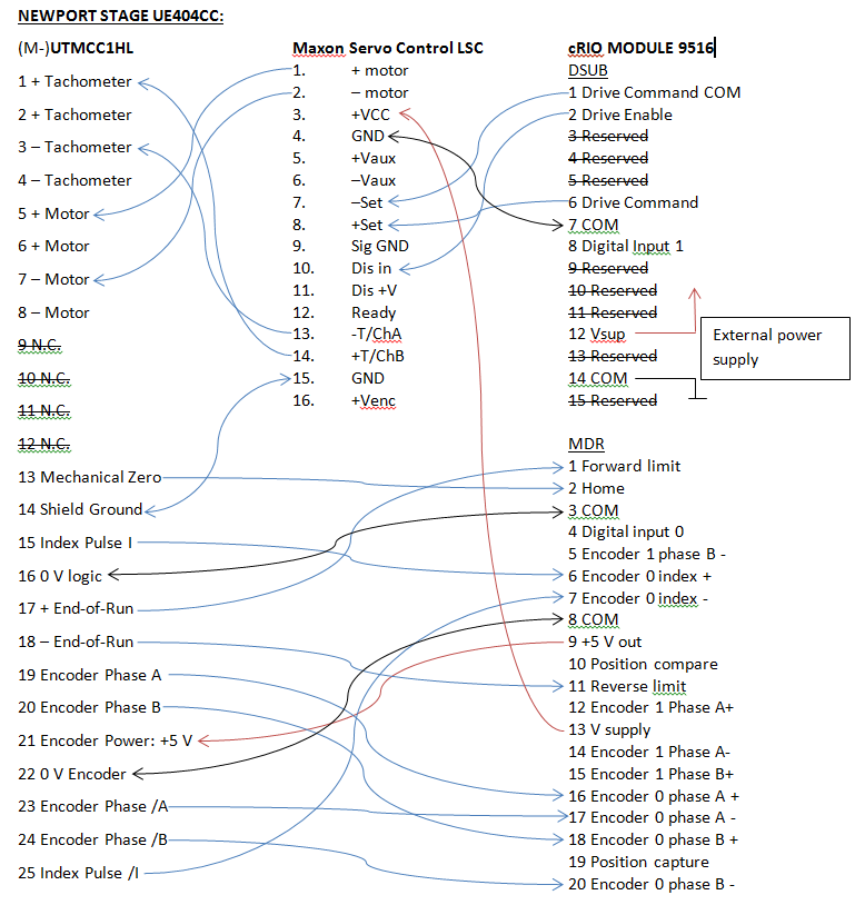
Hello
Currently, I am controlling a Newport plate using a cRIO, controller of Servo of Maxon and one NI Servo Drive Interface module. My configuration is:
- LabVIEW 2011 SP1
- F1 OR SoftMotion Module Premium 2011 SP1
- cRIO-9074
- NEITHER 9516 Servo Drive Interface
- MAXON 4-Q-DC Servo control LSC 30/2
- Newport Platinum: UTM150CC1HL (engine: UE404CC)
After looking through the books, I wired the linear step, controller of servo and 9516 module as follows:
(Wiring diagram .doc attached as well)
Note: the only difference between the pattern of wiring and I install, is that I disconnected the 9516 'Drive turn on' the Maxon "say in." That's fine with the LSC Maxon as if 'say IN' is not connected or to ground potential the power stage is activated.
Before wiring this configuration, I used the LSC Maxon and the scene of the UTM of Newport with an external power supply and controlled the step with internal potentiometer of Maxon. This succeeded.
Now I'm trying to control the scene with NI SoftMotion and am following the "Getting Started with NI 951 x series C Modules and LabVIEW" manual. I followed the manual and an axis of configuration and coordinate space in the Project Explorer and then tried to test the scene with the interactive Test Panel. After this step, it's where I run into problems. I can get the scene to move when changing the Position of the target, but any value I enter the Position of the target, the step will be only a small amount. If I put a positive value, it will move a sense, a negative value, it moves in the opposite direction. No matter if I put rev 10 000 or 100 rev the scene moves the same amount.
In my view, that the encoder works because when I move the scene manually the value of the current Position on the interactive Test Panel changes accordingly.
I'm a novice at this type of control so am not sure how to make sure my installation works correctly. I don't think that this is because the scene shifts only in small increments. Any help on what I should check/adjust to get my system working properly is much appreciated.
Thank you
Kyle
(Manuals for Maxon Servo controller and Newport Platinum are attached)
Usually when you have no control of the position and the axis continues to operate, then there is an inversion of the order. This usually results in a complete couple runaway. I would lower the position limit back to where is was and Exchange A and / not son. Try to run it again and see if you have the control. Don't forget that you have a way to stop the axis(E-stop) in case this new wiring translates into a real runaway.
-
Cannot run Simulink DLLs at the same time that the execution of the target time real VI
Hello
What I try to do is run a dll created in the Simulink model to control some servo through a CompactRio 9014.
For the moment, I managed to create three screws
(1) in the FPGA target that performs the PWM channel desired
(2) which takes the value of a variable that contains the desired position and network that feeds to the 1st VI
(3) a VI that is running on the host computer that changes the value of the network variable to change the position
I can get these three work screw and the servo controlled, but when I try to update the value of the network variable using simulation, by deploying to the target of RT simulation and running, he said:
' Access denied: this objective is already used by another host or project. »
I guess that's because the project is already connected the cRio, so I unplug and am able to deploy the model files.
However, when I try to run one of the screws in the Targer RT as well as simulation I get the error:
"This VI is downloaded to the target, but is not present in the project you are trying to deploy. All the screws on the target will be closed unless you choose to add the missing project VI. »
With a large number of missing screws...
I'd do this wrong, i.e. is there a simpler way to control inputs FPGA using the simulation, or is there something I have missed?
Thank you
Geoff
Hi Geoff,
I think I understand what you're trying to do and what you've done so far.
If I'm not mistaken you have passed through the SIT connection manager, set your target RT (select DLL, mappings and hardware i/o) and this is his 'magic '. If this is the case of look for the project pilot LabVIEW which was created by the SIT connection manager. This should live in the same folder where is your DLL. Open the pilot project, search for VI driver and open it. Then go into the Sub - VI # 5 has with the name of the loop rate Base. It's the Subvi who reads/writes on the material and the reads/writes the data to the DLL/OUT model. If you want to read the output of your model and then manipulate the data that is where you need to add your code.
Inside of this Base rate loop VI there is a Subvi with number 4 and called SIT take model Timestep. This VI is the one who makes the call to the DLL model. The output of this VI is your data from the model. This data goes into slot - VI # 5, which is responsible for the drafting of these data to the material. Since you want to manipulate that data from the model, you need to recover data from the wire coming from the Subvi 4 (SIT take model Timestep) before it gets to the Subvi # 5.
In this VI of Base rate loop, you will see that there are a few empty block structures. These images are for you to put any code you want. The reason is that any changes you make to the driver VI and subVIs that aren't inside of these frame structure will be lost if you decide to go in the connection manager to sit DOWN again and make some changes. The VI pilot gets new script whenever you do something in the SIT connection manager. Whatever it is inside these frames will not be erased.
So, if you have a code you want to run in parallel to the simulation you just have to drop it inside this driver VI. Very probably within this Subvi 5 (Base rate loop). To add your code just drop the VI in one of these settings and make any changes that him so that he can read the data in the model. Furthermore, the model (Subvi 5) data in a table. For the index of each element in the array and its meaning look for a file in the same folder where the DLL is named
readme.txt ports. This file has a description of the inports and small ports and their indexes. This VI driver is called when run you the host VI so you won't have to run sepearately.
Kind regards
Ricardo
National Instruments
Systems engineering
Maybe you are looking for
-
How can I remove Brand Thunder?
How can I remove Brand Thunder? It's boring. It isn't in my modules under extensions or appearance.
-
Satellite Pro M70 overheats and turns off
Need to support some tech with this problem. Satellite Pro M70 constant over heating problem. After use of 20-30 minutes of normal (web navigation etc.) the bottom of the laptop becomes really hot near the fan, unbearably hot to the touch.If I play g
-
What version of windows do need it to upgrade?
I couldn't upgrade my windows 2000 to XP or anything newer. I started to use firefox because it didn't slow down my computer and exployer I never liked. If I update the Flash Player do you recommend it will slow down my computer? I would like to know
-
Satellite A300 - 10 M: how install driver WLAN
I downloaded the Atheros WLAN driver but do not know what are the files to be opened to load the driver on the laptop. Any help, please? Thank you
-
HP pavilion dv5000: power on password
My lock screen says system disabled [14154]