servo
Hello.
I need to educate yourself on the hydraulic servo control with Labview. I have the card DAQ 6024. Can I control the servo-valve with 6024 map and Labview 6.1 and also for the position of the hydraulic cylinder, I will use a lineer potantiomater.
For example I thank you for your advise...
Hello
The 6024 will be able to send and read voltage signals, but you will need to implement the control algorithm in LabVIEW. There is no specific toolkit or a set of functions that NEITHER offer hydraulically controlled. If you have design control tools, you should be able to use it to implement some control algorithms. This application of closed-loop speed will depend largely on the PC that you run it like any process consuming RAM on this PC. Please send any specific questions that you have implemented your control application.
Tags: NI Software
Similar Questions
-
7344 PCI behave erratically, the random movements of servo
I use a PCI-7344 to control a 3-axis test bench. Today when I booted with on all the settings it has not worked, just kept servos moving randomly, even when controlled by MAX and a script of movement. Even the kill command has failed. I checked for the disconnected wires, but nothing has moved since the last time I used the system.
The servos for all axes acted weird. The current position, the target position and the following error message remained at zero, even though the engines were spinning. On an axis, the MAX software would show the current increase in position and values of random speed while the position of the target and following error message has remained at zero.
Something went wrong and I don't know how to fix it this time. Does anyone have an idea what to do? Since I was put on this project, I never enjoyed working with NOR-MAX or the PCI-7344. It seems I have spend more time to use it for experiments in fixing it.
It turns out that someone disconnected the cable used to power the PCI-7344. Once I plugged it back in it works well again.
-
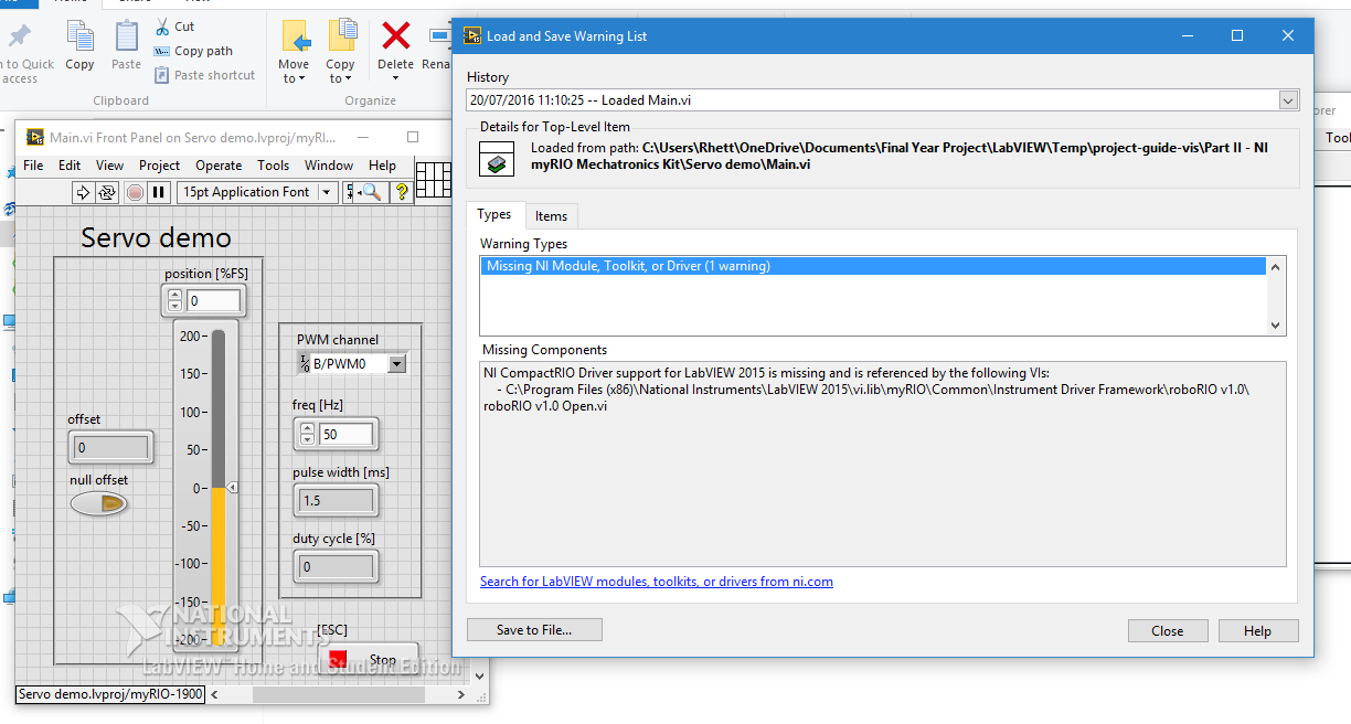
myRIO Servo demo does not: Servo sweeps back
Hi all
For the first time using LabVIEW and myRIO and I thought I'd run the demo of Servo. The question that it displays the following error message:
If I choose to ignore the error my servo works but don't stop at a point (hold the angle) and sweeps rather backward. This can be seen in the following video:
I'm honestly at a loss, I have virtually no experience with this hardware and software and the standard demo software does not work. I use an analog servo CS - 239 MG Corona.
Any help will be greatly appreciated

Hi Kathryn,
Thanks for all the help, you were extremely helpful
the solution was that I needed to power a battery pack as the myRIO provided far too little power. I found the solution in another forum of NOR and the OP knew exactly the same question. I have a battery pack on order and will update with the results.Kind regards
Rhett
-
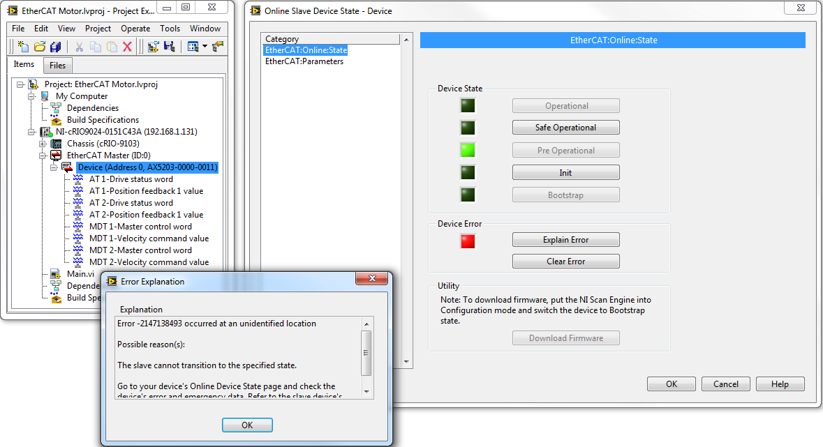
Servo on EtherCAT: parameter invalid when going from pre-op to SafeOp
Hello
I'm trying to control a 3rd party via EtherCAT servo drive:
- Material:
- Master: NOR-cRIO 9024
- Slave: Beckhoff AX5203
- Software:
- LabVIEW 2013 SP1 (32-bit)
- OR-Industrial Communications for EtherCAT 2.7
Use of the test panel LabVIEW (see image below), I am able to switch the slave between Bootstrap, Init, and States pre operational. The LCD screen on the slave displays the correct States I selected, so I know the basic EtherCAT link works.
However, when I try to transition from pre operational to the safe working condition, I get an error.
- LabVIEW, said 'the slave can not move to the specified state' (see image below)
- Display LCD slave displays error 0xF4A5, which, according to the website of Beckhoff , is "a parameter error has been detected in the SoE communication layer"
I'm at a loss at how to begin troubleshooting.
The explanation of the error says "go to the status page of the device your device online and check errors and emergency unit data. However, I find no error or given emergency in the Online slave device status page. There is that the "EtherCAT: online: State" and "EtherCAT: settings ' (picture above).
I wonder if this problem is related to any of the following:
- Import the XML device profile was not entirely successful. I described this to http://forums.ni.com/t5/Motion-Control-and-Motor-Drives/3rd-party-EtherCAT-slave-Importing-XML-Devic...
- My "EtherCAT: settings" page is empty, there is nothing in the dictionary of the object.
Advice would be greatly appreciated!
Hey,.
Obviously, NEITHER was able to get the ability to work with Beckhoff and supports so that officially AKD. So regarding NI Industrial Communications for EtherCAT supports the SoE, see the reply to your other post on the forum.
-
motor DC servo to matlab simulink
Hello
I like the design of servo motor dc to matlab simulink.but I don't know how to design so if someone can help me please
Hello
I think you post on a wrong forum... Why not try the Matlab forum?
In any case, have you looked at this for example:
http://CTMs.Engin.umich.edu/CTMs/index.php?example=MotorSpeed§ion=SimulinkModeling
http://www.MathWorks.com/help/physmod/Elec/UG/example--modeling-a-DC-motor.html
Best regards
K
-
NI 9514 free servo control jig
Hi, I have a Question because I still don't understand something on my program. First I use a cRIO 9022 and a NI 9514 module with an analog servo AKD drive to control my engine. I already have one using VI scan mode interface and the SoftMotion function blocks and it works OK. The problem is that, from what I understand, this scan mode uses the scan engine clock, where the minimum of research is period 5 ms. I'm running my engine between 500 and 2000 rpm and the "only" thing that I need is to send a signal of TTL output to a given position that I use as a control variable. (I use a NI 9401 for this attached to the block function Position compare). As I said, it works but not very accurate and there are only 2 options, either the control loop is too slow, or it has jitter in the other system I use (I can take images of the rotor and see with precision the angle and 1 or 2 degrees is a big mistake for me, which means that only 0.5 ms in time If I use 720 rpm for example. I'm now 5 to 6 degrees of error).
If my order is the problem, how can I make sure it's the VI the problem and can I do to fix this? I read here http://forums.ni.com/t5/LabVIEW/NI-9514-FPGA-and-SoftMotion/m-p/2173030#M699003 even if I use FPGA with my NI 9514 I still cannot remove the scan engine.
Thank you very much!
Italo
Hi Italo,
Here are some answers to your questions:
-If you can access the PIN Position compare, then you should be fine without the hardware connector that I mentioned in my previous post.
-The exit of the hairpin to compare position is a TTL signal 5V that you can access and use as your digital triggering. This will eventually cause at a pace much more reliable that the digital triggering generated you through the 9401 using the analytical engine.
-Your scanning interface program should continue to work properly. The program that you are using is able to drive the motor at the rate you were hoping for, the only problem is that we are relying on the analytical engine for digital triggering on the 9401, which does not give you the resolution of trigger, you needed. Using the PIN Position compare since the 9514 addresses this concern for us.
-
Servos and HC-SR04 in a code (arduino)
Hi guys,.
How can we use servos and HC-sr04 in the same code?
I'm in a situation of catch 22 where I can't use both of them as LINX supports HC-SR04 but no servos, LIFA media servos but not the HC-SR04.
I am stuggling to make a Subvi pulseIn for this.
Is there any solution for this?
It's the easiest way to do it! In fact, the hardest part is written the Arduino for the custom code. From the link I sent you, there's a Subvi, which already exists to invoke the custom command you defined.
The toolkits Arduino, both work in the same way - you run a firmware pre-compiled on the Arduino which is the interface between the hardware and it speaks to LabVIEW using a protocol series. The Toolbox said, you don't need to write LabVIEW code for the serial Protocol, nor do you need to write the Arduino Sketch yourself. The fact that you can change the sketch to add custom commands is a very powerful feature and saves you more having to write your own sketch (or LabVIEW code) from scratch!
-
Pulse/counter of encoder data wrong servo motor
First of all, I am very new to the use of labview. I'm trying to complete a project, a former employee was working on that.
For a quick background on what I'm working with, I use an NI DAQCard-6036E connected to a SC-2345. SC-2345 is then connected to a load cell, Omron R88D servo driver and an omron servo motor. The actuator is an incremental encoder with resolution of about 2048 pulses per revolution. My labview program includes a counter that records the data of the encoder on the servo-motor. I was able to get accurate data during the test through the program of measurement and automation of the engine manually. Also when running through the specific DAQ assistant, I use for my counter, I'm getting correct readings by turning manually engine. Once I run my full program, instead of get 2048 pulses per turn, I'm between 34000 and 36000 pulses per revolution. The more logical assumption is that I get vibrations in the engine itself or some kind of noise disturbs my signal. First, I tried to change the possible settings via the omron servo driver that could reduce the vibrations of the engine. I try to change the stiffness settings, enable, and disable the automatic adjustment feature and a few other parameters specified by the user manual which could cause vibrations. If turn the settings from rigidity as low as possible, I am able to get around 2000 impulses per turn, but data are very sporadic. In addition, my equipment must be very stiff, and with setting the lower rigidity for the servo driver, I can almost stop the engine with a minimum of force. My equipment must be able to travel at a near constant speed with fluctuations of up to 200 N force. Any suggestions on the direction in which I should go in search of a countermeasure?
Thank you
Experience with actuators is that they can produce large quantities of electrical noise. I guess that noise can enter the signal of coders. Look carefully at your wiring and make sure that you do not have a ground loop between your hardware OR and the actuator.
-
myRIO digital servo drive with PWM
After scouring the internet for answers, I realized that I have neglected this resource.
I'm testing some small digital servos that will be used in a senior design project. When we received the myRIO I created a simple VI to drive a servo using PWM with a frequency of 50 Hz and by varying the duty cycle between 5 to 10%. I used a good servo is provided with an arduino kit, and it worked perfectly. However, the Blue Bird BMS-385DMAX servos arrived and when I tried with the VI I did, it didn't work. I confirmed that the servo works by running with an arduino, it just does not work with the myRIO. I'm not an expert of labview, and I'm new to the platform of RIO; any advice would be greatly appreciated.
I joined the project. Ignore the KeyDutyCycle VI and the variable shared; It was something I experienced, but has not used.
You use the myRIO + 5v and Gnd of to power the Servo?
MyRIO + 5v is limited to 100 my output which may not be sufficient to power the larger servo. Try feeding the enslavement of another source, but still using the PWM myRIO. MyRIO PWM (and all other outputs digial) should be ~3.33v as 'high '.
-Sam K
Join us / follow theGroup of pirates of LabVIEW on google +
-
I'm pulling my hair out here... I hope someone can help to guide me in the right direction. I'm just learning binary and hex, so please forgive me (and correct me!) if I say something wrong. I have to give credit when it is deserved, because I use info from a post on theautochannel.com to drive this development.
I try to control a small indoor RC helicopter using LabVIEW and a USB joystick. I communicate with a transmitter wireless via rs232 (TTL converted), the Protocol is 125000, 8n1. Each image is 14 bytes 2 bytes of header. I would like to transmit data PPM (pulse position modulation) which is actually just a 10bits (1024 possible measures) range that dictates the position of the servo, for each channel.
Byte 3 & 4 are channel 1, byte 5 and 6 are channels 2, 7 & 8 CH 3,... and so on until the bytes 13 & 14 which is CH 6.
Each pair of bytes begins with "00" (binary).
Byte 3 & 4 should look like "00 00 00 xx xx xx xx xx", where the first "00" is the header, then "00 00" is the identifier of the servo, and 'xx xx xx xx xx' represents the position of the servo. The identifier is actually integrated in the position of the servo, the bits serve a double purpose.
That's why it all will look like this:
CH 01:00 00 00 xx xx xx xx xx (position has a valid range from 0 - 1023)
CH 02:00 00 01 xx xx xx xx xx (range 1024-2047)
CH 03:00 00 10 xx xx xx xx xx (range 2048-3071)
etc... If you convert the binary range, you can see how the second half of the bits ID servo are provided by the range of servo.
I intend by entry VISA to send every byte to constitute the entire frame, and then I will pause ~ 10ms between frames. However, my question is how the hell should I code this? !! I think I need to write, take 1 CH for example, bytes 3 and 4 together into a string and then split them back hand to be sent as two distinct bytes. However, I do not know how to mix my header and the first two bits of my ID servo, which is binary '00 xx', with my servo position (which I know I can write in decimal form, as entry VISA will convert it in binary). Any thoughts on the best way to do so, given all this?
An empty string character likens to a binary "0"?
Has totally confused everyone? I really hope not, but I'm pretty tired so let me know if I need to simplify my question. I hope someone can enlighten me as to the best way to combine the binary constant w modification of decimals (or hex). And if anyone has thoughts about a good way to organize my vi together, I understand that too! Right now I'll just use the structures of sequence... I post my code but at the moment, there is not much to look at
Thank you very much!!
No, you do not confuse everyone, but I think you might have confused yourself.

You basically need to do is to create the array of bytes that will be sent, and then use the array of bytes to a string, so you can send it to the serial port. The creation of the byte array can be done in several ways. You deal with 6 16-bit numbers, of which the lower 10 bits are the values of the position of the servo. I don't know what you want on the front panel to look like, but if you have 6 separate (one for each servo) controls with each set having a range of 0 to 1023 (for 10-bit), then you just have to OR each value based on the number of servo. Put all this in a table, add the bytes of the header and the array of bytes to a string allows to get a string that you can send via the serial port. You can also do this in a loop. Joined a VI to show the two concepts. You have not indicated what version of LabVIEW, is 8.2 you use.
-
Servo motor RC directly from sbRIO e/s digital
Hello
I would use a Committee sbRIO to fly a RC servo.
A RC servo control is usually reading a signal modulated TTL level pulse width.
Calendar will be no problem in using a sbRIO, for the FPGA can manage that.
But I am concerned about the level of output voltage of the output digital sbRIO; High level, it is specified as being > 2, 7V (max 3, 3V). It seems to be ok with the high level of TTL level requirement, but I wonder if anyone has tried this.
Thank you very much for comment, that you will have on this subject.
Tony
Hi Tony,.
http://digital.NI.com/public.nsf/allkb/ACB4BD7550C4374C86256BFB0067A4BD
This is compatible with TTL.
Kind regards
Bottom
-
interruption of a structure of consumption of prodcer to regularly test the position of the servo
Hey guys, I'm relatively new to labview and currently trying to make a multi snake like robot scene. I was interfacing with Controllers USB pololu and the need to manually control the first step and I have the remaining steps to follow, I have the first stage, using the controls on the front panel. I use a model of consumption of the producer and have pushed the button Activate an event and then queued a case in a second "loop of material."
my current problem is now I want to start working on the control of the secondary step passively, so I want to move the front of the stage tilted upward and then start rolling on before and the second stage begins to follow in the same position. I want to interrupt regularly and check the positions on the servos to compare and to act accordingly. My first thought is to interrupt the timeout in the case where structure and test if the servos are in the same position. the problem is that my visa reference is in the other loop.
What would be the best way to go about this? should I just queued in my gear loop on a time out and then test the position of the servo. or is there a way to share my visa resources in the loop of the producer? I originally wanted to store the reference in the loop of producer and pass whenever I went to the consumer loop but I couldn't figure a way to return the updated reference and I kept getting errors.
call loops are an option here? any advice would be helpful. even if you have a better structure to redo the entire project. I'd love to hear it for next time if nothing else. also if theres a better void / forum bad gladly move the pole.
Thank you guys
1. I aim to convey information/data to the loop of the reactor of the user interface. Leave the loop creator UI just intercept the events of GUI and send jobs to the reactor loop. You can create more brains to the reactor loop and let it also receive the strap of material information/work.
2. a simple concept for a regular position servo application would be an additional loop. It's the only work is have a wait timer, then queue on demand to the loop material to ask him to send the position of the servo. It will send to the loop of the reactor, as always, and the loop of the reactor will have built to react appropriately when it gets the position of servo information.
3. I would not speak for the servos in any other place that the loop of material. There are all kinds of mess if you can send orders series of different loops at the same time, can receive the answer poorly or not at all.
Sorry, don't have time to go into details, but hope this helps a little, when you think about the implementation of the app.
-Kevin P
4 P.S. I also wanted to talk about: it seems that both your reactor and Hardware loop are consumers of the same queue. Although I see not how did you preview first and then queue only if necessary, he is still not a recommended approach. Consider: If a loop is blocked when one of his messages is in the front of the queue, it will make the other loop stuck too.
-
Command of RC Servo motion control/KollMorgen AKD Modbus
I'm just learning about LabView on a project to control a RC Servo. I have implemented a train VI with a USB-6210 pulse generator and you can control the position of the servo using a button control. I want to be able to program the movement of the servo to follow a sine, square and triangle wave. I tried to use the function VI generator to generate the signal but can't get the servo to move. Someone can give me some tips on how to generate the desired waveform and use it to vary continuously the duty cycle of the pulse train? I thought that it would just to replace the button with the function of driving control?
My ultimate goal is to use the concept of driving a car KollMorgen AKD using Modbus to perform a similar function.
The express VI allows you to simulate the sinusoidal signal only circulates once only 1 data point out. In order to run continuously, you need to place inside a loop. I don't see an interest to use a local variable for your PWM control button. Should he wire directly to the vi "Not equal?" inside the loop. If you try to replace the control of knowledge with the sinus generator then you must put the generator sined inside the loop and the wiring that directly to the where you have connected PWM local variable.
-
RS232 driver vi for Advanced Motion Controls Digiflex Performance Servo Drive
I was wondering if one has developed a driver vi rs232 to control a servo Digiflex AMC. I'm not a guy aware of rs232 driver and this seems the only way to control this Driveware drive other than using the software supplied with the player. There are a few control files that are labeled Active X, but in fact do not work with the property to invoke. The Protocol series "focuses on the character, binary, master-slave." After calling the record company their guru said he knows of only Labview Guy who took this task and has been a success. The only information that it could give me was that he lived in the (San Francisco) Bay area.
Thank you
MCE
MCE,
Unfortunately, our collection of instruments (ni.com/idnet) driver has not all the drivers for your device from the CMA.
You can still use LabVIEW to communicate via RS232 to your device. You will get to know very well the manual of your device programming
here are some other links that may be useful:General concepts of Serial Communication
Instrument control tutorial series
Kind regards
-
My eos 500 d take pictures to less than the value of the manual and HAVE the value servo... Help!
Hi all. my camera will not take photos more in automatic mode or manual mode unless I have it HAVE servo value. It will be always filming and take pictures of in this mode. the problem is the same with all lenses. Anyone have any ideas?
Assuming that you test in Nice bright lighting, it is probably a failure of the lens, but there's a little more tests needed to be sure. When the appliance is in mode "One Shot" (not in "AI Servo" mode) the camera also uses what is called the "Update priority". This means that when you press the shutter button to take the picture, the 'priority' is on the guarantee that the camera was focused BEFORE it will allow the camera taking the picture. If you pass in "AI Servo" mode, the camera switches to what is called the "release priority" (most popular with sports and action). Priority of release explains that when you press the shutter button... the most important thing is that the camera taking the picture "right now" (if the camera had time to focus or not).
Once again, you must have enough light to test (outside on a day... that's fine). Don't test it in dark situations - especially on the subjects of low contrast.
Please turn on the camcorder in "live view" mode, with the target set to autofocus (AF/MF switch on the position of the AF).
It to focus and take a picture?
The reason I ask is because your camera has in fact two independent autofocus systems. He uses a normal mode (looking in the viewfinder to frame the shot) and the other in "liveview" mode (when using the LCD screen on the back to the chassis so.).
It is extremely unlikely that two development systems can fail (because they are independent of each other. The camera uses one or the other, never both at the same time.) If the camera cannot focus with ONE of these two methods point, then the problem is more likely to be objective.
The camera sends signals to the intermediate target electronic contacts that you see at the back of the lens. But the engines are actually inside the lens itself. If the lens electronics or engine does not then the lens will not focus, and since you are in 'One Shot' with "Priority Focus" mode, the camera will refuse to take the picture because it cannot lock the focus. BTW... If you pass the lens to position "MF", the camera will still be the shot because the camera is no longer trying to focus.
If you have more than one objective... try using a different lens.
Maybe you are looking for
-
whenever the browser now opens, it opens to yahoo where a popup lights and say you are selected for a prize with a value of at least $50, if you take a short survey. It crashes me to do anything. same thing when I go to facebook but no other site. it
-
Hello I want to upgrade the memory of my laptop. It was delivered with 2x256MB modules and now I would like to know:-If it should always be two modules installed (like 2x512MB, 2x1024Mo etc - otherwise, I would install a single module of 1 GB)?-If I
-
Council of low profile counters/timers
NOR (or someone else) made a profile Board low counter/timer? Perhaps with similar to 6602 record? If no, are there other options I could look in (I think that sampling rate may be too high to use USB)?
-
Here at this level a bit if possible, anyone know what I can install the fastest processor please
-
Construction (error internal.llb) .exe error
Hi all I have built many exe, but for some reason, this one is hard! I get an error that says: Error 1003 has occurred at \\Rochester\mtp\Test Rigs\NC4\NC4 Air Cap\Code Development\Air CAP v2.0\exe\internal.llb\Air v2.1.vi Rig inspection Cap I spent