One button dialogue by digital input
Hello
A question about the Vi of dialog a button. I have a request I want to change. We have a physical button connected to a digital input when it is pushed on Board that we want to move forward in the labview program. This is just a momentary pushbutton if. The way his game up to now the user is told to press the Start button and click OK in the dialog box only one button. See code. The way its programmed, they have to hold the button down and click OK. Works great so far.
We change the environment to give the operator the ability to use the keys by a strop when the unit under test, which means that they will no longer able to click with the mouse. This code is used in quite a few places... I was wondering if there was a real quick way to change this so that the user should not click on OK to continue in the Code.
See attachment!
Thank you
An indicator of the great string on the front panel. Display the prompt of the indicator. You can change the color or to Flash through property nodes, if you wish. Clear the flag by writing an empty string when you push the external button.
you need to hide the other parts of the façade while the prompt, you can use the Visible property for the KPI tabs. A tab with only the quick flag looks a lot like a dialog box or be customized in just like you want. Make tab an indicator (change control) and what page by simply writing to its controlling terminal. You can do some very versatile user interfaces with relatively little effort programming like this.
Lynn
Tags: NI Software
Similar Questions
-
Trying to create a push-button locking with digital inputs
Hello world
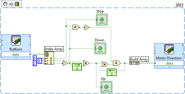
I am writing a program to control a motor with 3 push buttons, upwards, downwards and stop. I want the top button to lock when pushed and delatch when the stop or down are pushed. I tried the example program Latch.vi REARMABLE of this Web site, but no luck. It seems that out of the gate AND is indeterminate. I have attached to my program, any help would be great! Thank you
Use Index Array to get the desired Boolean value of the table. If you do the wiring one index, it will give you element 0. With this, you can have all the switches wired to different pins of the same registry on your DAQ hardware. Then, you can read a byte and unravel what bit does what. You will also need to build Boolean individuale in a table before you write in the acquisition of data. Here's a quick example:
You must decide which games to buttons that bit. I have not yet checked your lock algorithm logic.
-
Raising an event based on digital input? Treatment of a condition of emergency stop
I'm working on a test sequence into LabVIEW. I have a security which I am followed by a digital input the relay status, and I would like to pass to my failed state that I am in a State of emergency. (In my case, this happens when a barrier is broken or emergency push button is pressed).
It would be easy to do if I could use a digital input to trigger an event. However, this doesn't seem to be possible. I tried bind my digital input to a control, and then follow the State of the control as an event, but that doesn't seem to work.
My main problem is that I can be in one of the stages of test 5 seconds approximately. So far, I have not found a way to out or interrupt this step if my digital input changes state. I can get it to transition to the failed state after the step in progress, but I want that it to transition immediately when the safety relay is broken.
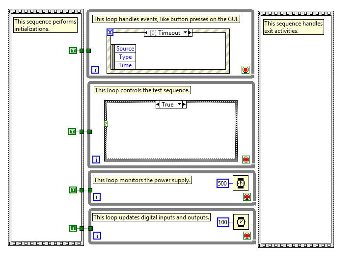
I've attached a picture that shows the basic structure of my program. The actual program is much more complicated, so I hope this is enough information to get started. I have stops in each loop attached together with the help of a subvi, which basically returns a Boolean TRUE if you press the 'stop' on the operator interface (it is one of the events of my structure of the event).
It seems that it would be a fairly common situation that there must be some answer I'm missing. Can anyone help? Thanks in advance...
You need (somewhere) a loop that monitors the digital status and can detect the transition Fail. The timing of this loop of 'surveillance' apply to how fast you can respond to failure.
But now you need to trigger an event when this happens. When I started programming in LabVIEW, I learned on the events of signs of value that could trigger programmatically a value indicator has changed. However, a few years later I learned the user events, a more flexible method for generation "software interrupts' who have a number of advantages over value of signage.
I don't know if you are looking for using LabVIEW or LabVIEW examples user events you'll find a good explanation for how to use these (use the Help Index, and then type user name).
Bob Schor
-
Digital input and output problem
Hello:
I do a test for digital i/o:
for a table of the digital signal to an output of data acquisition in the digital input to detect the output signal.
(bascially, it's like a loop that goes outside the material)It's pretty simple, as shown in the attached fichier_1.
It works well.
The manual light switch controls, which means that inputs and outputs are ok.Then I went on the low level DAQ for better speed, as in attached fichier_2.
But it does not work. Especially when I pressed stop to abort the loop, an error has occurred:To speed up, I went to the low-level data acquisition as the fichier_2 attached.
But it does not work. Espeically when I press the "stop"button to exit the loop, the error occurs.Possible reasons:
Requested value is not supported for this property value.
The value of the property may be invalid because it is in conflict with another property.Property: SampTimingType
Asked the value large clock
You can select: on requestI don't understand why the sampling time has a conflict here.
(It is probably just something very simple in data acquisition, but I checked a few examples and did not find a clue).
Hope someone can give me a suggestion.Ultimately, my goal is to make the attached file_3.
In this one, I generate a digital output, and then lead to the entrance.
Then I can take it as a signal to trigger my other task.Note:
I use a similar conti signal to control one of my camera.
I need to sync it with my another task.
So I think to generate a digital output (which share the same clock as the signal similar to the data acquisition device), then put it in one of the digital input.
By detecting this digital input, I can trigger my task and synchronize with this signal similar.
My camera's USB-6211.
I am aware of the latency of USB, but once the value is a constant value, then the synchronization is always good for me.
Actually, I was using an analogue at the entrance of the to do it before, it may work, but the synchronization error is too big for me.
I need to do some calculations/judgment for this analog value, which makes the time difference varies.
So I'm trying digital entry now and I hope that the digital input can trigger my task with a stable latency.Thank you very much
Have you looked at the specs? It clearly states that the digital I/o is a programmed software. You have not any hardware clock at all. The best rate that you could possibly achieve is around 1 kHz and which would have a considerable jitter the nature of non-determimistic of windows.
-
Hello
I searched for centuries for the answer to what I thought was a simple question - the iMac has one digital input (optical or other)?
I know that the headphone port doubles as an analog audio to as well as an optical digital output, but this port also accepts input optical? If not, is it possible to enter a digital signal via a USB port?
I have an iMac (20-inch, mid 2007).
Thanks to all who can help.
AL
Yes exit usb audio and are truly comprehensive external soundcards, they can have any type of entry and exit of the machine to be desired that they have
and if they do a driver of OS x for him it's just a matter of connection installing the driver and choosing the entry in system preferences for being that
If the audio minijack that also take in charge the headset for iPhone I believe support the digital input and I don't know if
-
Hello
I am relative new to LabWindows.
I have a program that starts when I press a button. The program controls a motor. Now I press a button on the motor and the program must cease (Safty Stop). The button is connected to a digital input on my card (PCI Express 6343). Now, I have the question, how do I program the interruption? I know not how do in CVI (controls the digital input whenever the program runs).
I hope someone can help me.
Best regards
The starting point must be to look relevant examples that NEITHER provide:
ReadDigChan - ChangeDetection.prj
and
ReadDigChan - ChangeDetectionEvent.prj
However, I must advice against using a PC as a "Safety Stop". As a general rule, the PC are completely inappropriate to the core functions of security, unless you follow the standard IEC 62304 relevent to the letter. Tip: it's hard to do with a PC. To implement safety functions such as emergency and interlocks stops you buy much better a specialist dedicated safety relay and following the instructions of the manufacturer. If life-threatening energy (either electric or medcanical) may be present, then consult a professional engineer.
-
How can I set up a digital input task to read continuous samples?
I am trying to create an exclusively digital task that will make digital readings at a rate timed by the material using a PCIe-6509. However, when I try to put the task timing as follows (which works on a PCIe-6509), I get the following error:
Requested value is not supported for this property value. The value of the property may be invalid because it is in conflict with another property.
Property: NationalInstruments.DAQmx.Timing.SampleTimingType
Required value: NationalInstruments.DAQmx.SampleTimingType.SampleClock
Possible values: NationalInstruments.DAQmx.SampleTimingType.OnDemand, NationalInstruments.DAQmx.SampleTimingType.ChangeDetection
Task name: DigitalInputTask
State code:-200077
The relevant parts of my code are:
public class DigitalInputReader: IDisposable
{
public DigitalInputReader()
{
dataReadyHandler = new System.AsyncCallback (DataReadyEventHandler);daqmxTask = new DigitalInputTask();
daqmxTask.Configure (Globals.NI);daqmxTask.Control (TaskAction.Verify);
daqmxTask.Control (TaskAction.Commit);daqmxReader = new DigitalMultiChannelReader (daqmxTask.Stream);
}public class DigitalInputTask: task
{public DigitalInputTask(): {base ("DigitalInputTask")}
public virtual void Configure (NiConfiguration niConfig)
{
<= niconfig.digitalinputs.count="" -="" 1;="">
{
String physicalChannelName = niConfig.Device + "/ port" + niConfig.DigitalInputs [i]. Port.ToString () + "/ line" + niConfig.DigitalInputs [i]. Channel.ToString ();
String nameToAssignToChannel = niConfig.DigitalInputs [i]. Name;DIChannel ch is this. DIChannels.CreateChannel (physicalChannelName, nameToAssignToChannel, ChannelLineGrouping.OneChannelForEachLine);
c. InvertLines = niConfig.DigitalInputs [i]. InvertLines;
}
var signalSource = "";
This. Timing.ConfigureSampleClock (signalSource, Globals.MachineSettings.SampleRate, SampleClockActiveEdge.Rising, SampleQuantityMode.ContinuousSamples);// Globals.MachineSettings.SamplesPerChannel);
}
}The last call to Task.Timing.ConfigureSampleClock, it's which throw errors.
Of the options available, or SampleTimingType.OnDemand or NationalInstruments.DAQmx.SampleTimingType.ChangeDetection provide the same precisely timed calls that I am familiar with the analog input interruptions.
How is it possible in a digital task? I mean, it seems that I could set up another task to do call by material for the production of a clock signal and use the ChangeDetection synchronization mode, but this seems a bit complicated for what should be easy to do. What Miss me?
Update: I thought about it. You cannot call ConfigureSampleClock when the digital input card is a device of 650 x, because these devices have any automated examples of clock. They are configured to run in mode default finite samples. You must make all sample synchronizing with these devices in the software.
Be cautious, however, because the .NET timers ensure they put any faster than their scheduled interval. In practice, they are usually 5 to 10 ms slow by tick. This means that if you want to read samples every 100 ms by sample clock, you'd end up reading all 108 ms samples. All counters based on the elapsed time and number of samples would be away after a few seconds of it.
Instead, you must do one of four things: write a doggone driver that runs in ring 0 and interfaces with the PCIe card in the required interval (i.e. on NC, not you, in practice), tolerate the inclination of the clock, use a multimedia timer as an interruption audio or video that is more likely to respond to the correct interval, or , my solution, an accurate clock allows you to set the interval of the timer. I wrote the following code to the timer:
var CorrectiveStopwatch = new System.Diagnostics.Stopwatch();

var CorrectedTimer = new System.Timers.Timer()

{
Interval = targetInterval,
AutoReset = true,
};
CorrectedTimer.Elapsed += (o, e) =>
{
var actualMilliseconds =;Adjust the next tick so that it's accurate
EG: Stopwatch says we're at 2015 ms, we should be at 2000 ms
2000 + 100 - 2015 = 85 and should trigger at the right time
var StopwatchCorrectedElapsedMilliseconds = newInterval +.
targetInterval-
CorrectiveStopwatch.ElapsedMilliseconds;If we're over 1 target interval too slow, trigger ASAP!
<=>
{
NvelIntervalle = 1;
}CorrectedTimer.Interval = NvelIntervalle;
StopwatchCorrectedElapsedMilliseconds += targetInterval;
};I hope this helps someone.
-
Hello
After reading everything that specifications and manuals, I decided to ask a general question.
In the data sheets, user guides I've read, in general, there are two warnings for DIO:
-Do not connect the outputs digital circuits which operates above the limits.
-Do not drive the line with tensions outside its operating range.
Generally speaking they tell me I need to know when dealing with output and voltage when dealing with entries. So I have this question, can I wire a power supply for digital inputs directly without exceeding its "beach of normal operation and without any protection circuit? In fact, my feelings, this is not possible. But why certain documents produced clearly mention that the impedance internal inputs while that of others is not clear those? How can I determine if I can connect a signal directly to an entry (for example USB-6525 indicates a current limiter circuit, but I don't see a clear explanation in the datasheet USB-6251)?
As long as the input voltages are within specified limits, no damage will be the DAQ hardware. Logic devices often have two lines of non overlapping input, one for low input and high input. If the input voltage lies between the beaches, the performance of the device can be unpredictable. Also, check your power supply to make sure that this doesn't not exceeding when turned on or off as that could exceed the DAQ limit.
Lynn
-
Hello
Is it possible to trigger action digital input using the signal I want to measure? In the example:
I want to measure PWM on P0.0 after first rising edge PWM on P0.0, but using only this line P0.0 (no PFI in use, only one used digital entry).
IM using X SERIES USB-6353.
Some DAQ cards can trigger on analog edge of the signal you want to measure. If a DI data extraction, it is possible to select only the PFI or similar as trigger. What is your application? What you want to achieve?
I can imagine you could workaround: record streaming samples of DI and do a SW trigger in your program, so you can get the same samples prédéclenchés (as in a digital oscilloscope).
-
6259 switch digital input to output
Hi all
I use the NI PXI-6259. One of the digital inputs I want to switch to digital output, send a serial code and switch again one digital input.
Does anyone have experience with this kind of configuration change during execution of the VI program.
Thank you
Basically delete the task that he had as an input, create another task DAQmx with channel configured as output, this task, erase it, create the task with channel configured as an input.
If you need a tight with switching schedule, I wouldn't recommend this Board. You may need to set up a Council of RIO with LabVIEW FPGA.
-
Hello
I'm learning about labview data acquisition. So, I made a base for digital vi, with a virtual digital input device. For some reason any I can not output anything other then zero, but when I run the daq assistant (when you install assistant daq) Boolean values between 0 and 1. But, in my VI I can't get any other input then set to zero.
I enclose my VI.
Thank you
You should associate your stop button at the entrance to Stop on the DAQ Assistant. You are openening and close the task each time when you do not do this. According to me, which is also reset the activation/deactivation of the simulated device.

-
Two button dialogue - fire once
I have an application where I need to get a lot of responses from the user through two button dialog boxes. I need to feel the change of State of a locked DI and when he goes UP, display a dialog of two buttons for the user to interact. As this happens inside a while loop 100ms, I need to remove the dialog box after the user selection is made. Otherwise the pop up will happen several times as the DI is locked in a HIGH State.
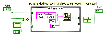
While I was able to get the feature with a registry change (see attachment to LV2009), I was wondering if there was a better way to do this kind of "once-only-messages?
Thank you
It is not a good idea to change the status of the digital input which is "read only".
The final VI with the required change is as below:
-
Best way to encode several digital inputs of choice / binary indicators
Hello.
I need some suggestions.
We have several libraries API (to control our material) written in C and distributed as a dll. For many of them, we have a library of LabVIEW VIs wrapping (using the call library function node).
We have several functions in which the entry (in the original C library) is an unsigned integer, which is supposed to be several flags ORed together (each value one bit).
I've seen more than one title, that this interface has been transferred to the wrapper live
1 digital input. User must understand and use it exactly like the C programmer
2 try to make more enjoyable - an entry that is a table, which appears on the front panel, as a sort of list box multiple choice of entry (internally in the block diagram that is used to create the correct entry to the C function)
I think there are others, but this is what I remember right now. When I saw option number 2 (looking at the front) I thought it was much more enjoyable. clearer and more intuitive (the user can select choice named, no, not strange %valeurs hexa%, etc.). However when I put on a block and tried to wire diagram, I had to provide an array of numbers; I had no idea what the values were supposed to be. Option 2 seems so much better for a user interface, but for an API, I think it's actually worse.
What do you see, if you were a programmer building my functions into your application?
Thank you.
Batya
Since each value is a bit simple, I would say that the wrapper have Boolean values in the connector pane and convert it internally to the correct bit field. Another option is to use a cluster of Boolean, but which may be less friendly to the user of the API. I suggest you do this only if you have several options.
-
How can I measure the time between each two successive increase edges, using digital input?
Hello
I have tried two measure the time in seconds between each two successive rising edges on a digital input.
So far I managed to detect the rising edge, increment a counter at each rising edge and take the time during which the increase is edge
all I need now is subtract edge currently rising from the previous era of edge rising to calculate (T), which can be 1/frequency and display in real time for the user.
but I do not know how to do this

Can someone help me please!
Woah!

Sorry Apok, but your code becomes much too complicated and salty. I don't think that all records to offset or Boolean conversion/operators are necessary at all.
If you want to measure the time between two keys so it's another (much less complicated) way. It simply records the time when press button in a registry change, then compares the two.
-
Question of the digital input USB-6009
Hello
I use USB-6009. I have problem in Input.I digital did not connect anything on all channels. But all of the DI/O channels generate 5 volts. And I tested the DI/operating system in the Test Panel also. All digital inputs are high. How I use it? Please suggest me the solution.
You're the one who said it was generating 5V. And I said that a fine should be detected as a logic one. Connect a gnd input.
When it starts, all of the default value of I/O at the entrances.
Maybe you are looking for
-
Hey mozilla, please consider the implementation of the option (in the privacy settings) always start in private mode.Thank you
-
How to enable virtualization in the BIOS of HP Pavilion p7 - 1227c
I was able to install Windows 2008 Server R2 and hyper v Server. The problem happens after you create the new virtual machine, and then start, this "the virtual machine could not be started because the hypervisor is not running. Thanks, in advance. T
-
WLAN stopped working - Satellite X 200/N00, Vista Ultimate 32-bit (SP1)
When I bought this laptop earlier this year, everything worked fine without any significant problems. A few weeks ago but my WLAN connection has stopped working - more specifically, it does not get a valid IP address of the router. Laptop is a Satell
-
Trying to find how to have a second screen for a HP TouchSmart 23-f2313? I currently use an Xbox 360 and Play to watch movies, etc. from the pc, but I can't find all the topics that cover how to add another graphics card or what options are available
-
My LCD is flashing. If I bend/wigggle it the flicker disappears. No idea what can be the reason?