OR USB-6008 control
Hello
I am currently using a map of measurement computing USB - DAQ 3101, but now uses a card DAQ NI USB-6008 and need a bit of help with conversions of connector and pinout. MC USB-3101 has a pinout 56, where, as the NI USB-6008 housing has a pinout 32. I've done the research, but found different results. Someone at - it a concrete conversion pdf or Web site for these conversions?
Thank you
Hello Steve,.
Thank you for your email back! I now see what you were asking. The VOUT1 and the VIOUT2 I feel would be the equivalent of the 6008 AO 0 1 AO and GND. So pines 14-16 These would be the pins that you would use to produce a voltage based on the specifications of the card. It is not a "NC" or not connects to the 6008, as all the pins are used. Let me know if it helps! Have a great day!
See you soon!
Corby_B
http://www.NI.com/support
Tags: NI Hardware
Similar Questions
-
MAX and Mac (to control on Labview, NI USB-6008)
Hi, I would like to order my USB NI 6008 card in my Mac. I'm using Labview, but I'm a real beginner. I get my sensor on my USB card data and I can use them in Labview to control an electric trolley. This project is for my review: engenering school.
So, on PC (Windows), it's ok, but on my mac, I do not find MAX. And if I understand, I need MAX to create the DAQ Assistant and a few other VI in Labview. However, I have yet install Base DASmx 3.4 for mac os.
Could you help me please?
I'm sorry for my English, it's so bad. I'm studying french and I'd rather post here because I found no answers in the french part of forums of NOR.
See youi soon.
Thank you
Thomas L
The USB-6008 camera is supported with DAQmx Base, Yes. You do not get MAX, but you can always control your USB-6008.
Install LabVIEW 2010 and DAQmx Base 3.4and this should give you the DAQmx Base vis in LabVIEW palettes.
-
NEITHER USB-6008 connect to thermocuples and pressure sensors, control valve
I am endevoring to build a gasification plant biomass for bench scale test process control plans. NEITHER USB-6008/6009 will be adapted for use as a data acquisition. I'll take RTDS, thermocouples and pressure sensors. I don't want to use industrial automation controllers. It is also possible to use the channel of analog output for sending signals to a control valve position (using sufficient current/voltage between the two drivers).
(1) OK. I just wanted to be sure that you were aware of the potential dangers.
(2) an RTD is a resistance that has small changes in resistance per degree of temperature change. To measure that you have need of a current source and a sufficient resolution in order to detect small changes. At 25 degrees C a typical RTD is 109,73 ohms and resistance ohms 0.38 per degree changes. If you had 1 my crossing this RTD voltage through it would be 109,7 mV and the voltage change of 0.38 mV by degree.
The resolution of the 6008 on the most sensitive range is 0.49 mV > 1 degree. The accuracy of the 6008 is 1.5 mV typical.
For a Type K thermocouple, voltage at 25 degrees is 1.407 mV and change by degree is 39 µV. Millivolt solving half of the 6008 translates into about 12 degrees.
If you need a source of excitement for RTD and a kind of amplification for thermocouples and RTD before she would make any sense to try to use USB-6008.
(3) I have not used anything except LabVIEW with DAQ devices and drivers. I think DAQmx can be used with MATLAB and other languages.
(4) the 6008 is the low range made by NOR. You will need to go to a more expensive camera or add signals conditioning circuits. Talk to your representative OR assistance in the choice of a suitable device.
Lynn
-
RELAY CONTROL WITH THE HELP OF USB-6008
Hi all I'm new to labview, I want to control the relay using USB-6008. could someone help me find valuable solution, because this is my final project mechanical engg. I need the electrical diagram and whether it is digital command also mention details of ports/lines I have to connect.
In this, I joined the relay diagram, in which I have to just to magnetize this nucleus to attract this soft iron. so I need to do ON and OFF. Please guide me and thanks in advance too.
-
Pt100 (USB-6008) configuration problems
Hello
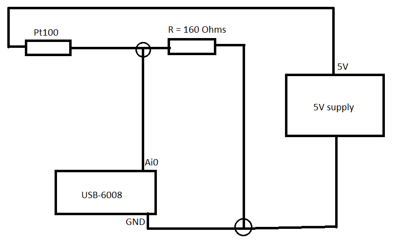
I'm using the hardware DAQ USB-6008 (I know that's not accurate and all) and I use the Pt100 (QAP2010, click for plug technique).
I connected it like this.
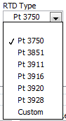
Now in LabVIEW, these are the only options (DAQmx new task-> acquire->-> RTD temperature signals).
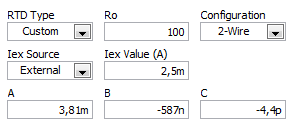
If I choose for custom settings, I get these options (I don't know what variables that is).
I use a small greenhouse where I need to measure the temperature and humidity and control environment (by using a fan to cool the cartridges to greenhouse and heat to heat).
My goal is to read the temperature using a graph on the front panel.
Can someone help me how configure/choose the right options? If you need more information I'll provide them as soon as possible!
A quick search for RTD class B shows the precision and the coefficient. As Fan Ravens stressed resistance according to the temperature is plotted in the data sheet. To control the temperature in greenhouse, a simple calculation of the slope of this graph is not good enough.
Note that the USB-6008 case limited an active player on the outputs analog and it controls only the voltage. So you will need at least one external resistor and possibly and external power to excite the RTD. These options that you have linked is not applicable to the USB-6008, which is a very simple device. You should perhaps simply to measure the voltage and calculate first resistance, then the temperature.
Lynn
-
Do another counter for usb-6008 VI using Labview 8.5
I want to create another counter for usb-6008 using Labview 8.5, it is necessary to calculate the two gears simultaneously.
The best way to proceed is to use the meter. The counter counts
signals without having to interrupt the system or use the USB bus.
When you ask the number of ticks that saw the meter, one
request is thrown from the CPU to the USB line to the 6008, which then
request counter "ticks how have you seen? This number is
returned on the USB bus, goes to the CPU and display on your
screen. Given that the DIO lines on the 6008 are software timed, it is
no way to guarantee that the data back to the central unit is
deterministic. The conceptual difference between software-controlled
DIO (that nondeterministically returns an entire stream) and a
meter software-tick-application-controlled (which returns a unique number
with the number of ticks) prevents us from using the DIO lines on the
6008. the best way to count more edges is buying more 6008 s.
Another possibility would be to buy a PCI card to counter such as
the PCI-6602, who owns 8 counters. Most of the counters we offer in the
USB form factor is 2 per device. -
USB 6008 analog i/o has stopped working
Hello
I have been using a USB-6008 for a few weeks now and it has worked well. I've been using the outputs digital, analog inputs and outputs this morning and they worked very well. I worked on something else for an hour or two and then resumed using the 6008, find the analog pins have stopped working. The show output analog on 1mV any value I send to them and the analog inputs always read - 10.3, despite limits MAX being set to 0 and + 5 (and me only using 0 - 5V on them). I tried all the inputs and outputs, in all ways (CSR, diff) with the same results. The digital outputs all work very well. Yes, he is grounded properly. Yes, the wires have continuity. My multimeter don't lie about me, either.
I took the MAX test panel to solve the problems. The unit passes its tests of self-control, and my Labview program does not return errors by contacting the 6008. I don't connected the 6008 which could exceed the voltage or the current limits of entrances and exits. In fact, all I did was unplug it when I stopped using it as soon as possible and then reconnected it when I went back to work. The material to which it is connected has been turned off during this time.
Any ideas? Thank you.
Problem is solved. If anyone finds this is interested, the problem was at the level of the material, that the 6008 has been connected. I'm covering, among other things, to a PIC Microcontroller. I just changed the oscillator on the PEAK, and inadvertently changed parameters parameters of the ADC as well. This caused the pin used as my reference voltage (connected to + 2, 5V output of 6008) to transform itself into a digital camera of output, a value of 0. This short-circuit the + 2, 5V output of the 6008, causing it to close.
Lesson learned: check your material carefully, even if it does not make the difference in a first time!
-
E/s digital USB-6008 changes when the system starts
I was intending to use the USB-6008 housing in a critical application in which the digital I/o lines are used to trigger relays. The relay should activate when I ask them programmatically. Otherwise, they must remain open. The problem is that during a reboot of the operating system, the e/s digital USB-6008 go up and down several times - opening and closing my relay. It is not acceptable for my application.
Is it possible to prevent the lines to reach logical high except if ordered to do so?
There is no way to set the startup on the 6008 States.
As the system USB boot devices and turns on power to the computer and off the power to the USB ports, on the DIO lines go up and down several times.
You will need to put a logic of material extra, just after data acquisition to ensure that potentially dangerous output combinations cannot affect the relay and the elements they control.
-
Loss of communications with USB-6008
I have a USB-6008 be used to control a couple of valves with its digital output channels. The digital output channels are a relay that energizes the solenoid valves (valves are 115VAC) switching. The USB device is connected to a USB port on laptop.
The software/hardware was working fine, then some time while it was connected there was a power surge. There was a 2 a fuse on the 115 VAC line that blew.
After this communication surge was no longer able to be implemented with the box USB-6008. Is it possible for a power surge affecting the USB device, even if his power comes from the power supply of 5V USB?
Things I checked so far.
Restart the computer with the USB unplugged and start back up - no connection
Check the Device Manager for the USB device to be present - not visible in the Device Manager
Check MAX for device - does not present as gift
Check the wiring to the son of course drop - no defeated cables
try on different laptops - connection
Connect other USB devices to the laptop USB - another fine feature of devices USB slot
Check the + 5V channel on the USB device and do not read a voltage
Any indication seems to be that, somehow, the USB device has been damaged during this surge? Is there some kind of diagnosis offline, I do without seeing the unit online?
Hello the plough,
It looks like the surge caused a sort of feedback of the valve of your USB device. This USB device is not designed for industrial applications and can easily be damaged in the situation you described. For a USB device with a greater ability to withstand this type of power surge, you should watch the box USB-6525. A better solution would be a CompactDAQ or CompactRIO system with a NI 9401, which is designed to withstand 1 000 Vrms, verified by a 5 s dielectric withstand test.
-
Error-200077, USB-6008, deterministic application
Hello
I acquire and generate analog signals using a device USB 6008 to achieve control of feedback. I use a loop of simulation to generate the output of the controller, so need to synchronize signals input/output with the calculation software. I have the following questions:
1. when I use a sample for the analog output clock, I get an error (-200077). What is the cause of this error and are there solutions?
2. what values of step size and calendar period (simulation loop settings) should I use to ensure that determinism?
Your comments are appreciated.
Thank you.
The 6008 doesn't have a clock output. It's software timed and so not deterministic.
-
USB-6008 appears in Device Manager but not in MAX or Labview
I use Windows 7 Ultimate 32-bit and you want to use a USB-6008 in LabVIEW 8.5.1. The device appears under data acquisition devices in the Windows Device Manager. The flashing on the device, but the device does not appear in the Explorer of Measurement & Automation 8.7.1. am I missing something?
He doubts.
First, check the easy things... to refresh the list of devices to MAX and see if it comes to that. I'm guessing you've already tried this, but it never hurts to check.
My bet is that it's a database corrupted Max. This happens from time to time. Usually when I see it, the 'Dev1' always appears in LabVIEW if you plop down constant DAQ hardware or control.
There are tools and processes to erase and start over with a new database, but in my experience, the best way to resolve it is simply update or reinstall MAX.
-
How can I improve the rate of acquisition with daqmx and usb-6008?
Hello
I am trying to acquire data of analog voltage with a USB-6008. I'm under Labview 8.5 student on an HP laptop with a 1.33 Ghz cpu and 736MB RAM, apparently. I tried using the Daq assistant and the low-level Daqmx functions. My best results come with a task set in MAX for my analog input, and using the function 'Daqmx read' the 'unique double 1 d sample' value in a while loop. I insert the values returned in a table which built in the while loop, and then when I'm done, I check the number of samples in the table. In the test VI attached, I also use the time to Get before and after all loop. The best sampling rate I made using this method, is around 40samples/second. I have attached a VI below that illustrates this concept. In my actual application, the data acquisition code runs at a time while loop with 1ms, parallel to other code that controls the device I'm collecting data of. The sampling rate is roughly the same for my test below VI and my application program.
The 6008 datasheet gives the sampling frequency maximum 10 kHz. I'd be happy with 2 to 2.5 kHz, or as soon as possible; I'm sure that I can achieve a little more than 40 Hz. My first idea was tied to the hardware, but the 6008 cannot make acquisitions NI hardware.
My question is: How can I implement a faster sampling of analog voltages to a USB-6008 in LAbview? If I can't do it, is there another way I can taste the data more quickly?
Thank you
-SK-

To the best of my knowledge, the USB-6008 can do timed equipment acquisition. Don't forget that this is a multiplexed device, so if you add 8 channels so the maximum you can set is 10 k/8
If you are new to LabVIEW, I suggest that you try this sample program first
\examples\DAQmx\Analog In\Measure voltage. llb\Acq & Graph tension-Int Clk.vi Amit
-
Incorrect value for analog output USB-6008. Cannot not out more than 3V
I use USB-6008 analog IO, but the analog output (AO0 or AO1) can go up to 3 - 3.5V. The output can follow accurately the value of 0 to 2, 5V, but then he start the values adjusted trolling and not can not spend you 3.5V exponentially.
The only strange thing the entire circuit is that I connected all patterns (analog source and I/O 5V) between them, but I don't see what affect the output.
Kind regards
ISSOKO
Thanks for the quick reply Ana.
It is not the Council NOR, nor the Council of motorization. Apparently, the interface for motor control (motor spirit C: solutions - cubed.com), load the analog output. A tension following actually isolated op amp output USB-6008 and solved the problem.
Best regards, ISSOKO
-
USB 6008 DI sampling frequency
Hello
I would like samples N to a digital input on 6008 channel. In the port of GOT it, it is possible to put samples/channel and sampling frequency, but I couldn't find a way to do the same for the channel of DI.
If I use MAX to read the N samples on request, I can increase or decrease the number of sampels to read but rates of mutation has no effect.
using the:
DAQmxErrChk (DAQmxCfgSampClkTiming (g_TaskHandle, "", samplesPerSecond, DAQmx_Val_Rising, DAQmx_Val_FiniteSamps, sampsPerChan));
also gives me error.
I don't know who do :-(
Concerning
RB
Hi RB,.
Digital I/o on the box USB-6008 are "static", meaning that they are controlled by the software. There is no sample clock to set the time a sample is read/written. Your software provides synchronization for DIO.
Measuring mode 'Samples on request' refers to avoiding.
Hardware timing (a sample clock) is available on most of the products OR providing DIO. As a low-cost product, the USB-6008 housing does not hardware timing for DIO.
Best regards, Topp
-
Reading NI USB 6008 of executable
Hi all
I tried to find a solution in existing topics, but unfortunately could not find a suitable solution.
I use a USB-6008 read a voltage on ai0. When I run the VI with the USB device connected to my development pc it works very well (DAQ assistant was used to read the value on ai0). After making an executable on my development pc also works. However, when I move the executable file on the computer on which I want to use it does not read voltage. If I start NI Max, I noticed that the computer is able to read the value, so physically everything should be good. To me, it seems that some link/link is missing from the software. Anyone know what may be missing/defective in my executable?
OR DAQmx is installed on the computer on which it is to run.
Is the device and channel named in the same way on desktop deployment as was the development of your PC? Display the MAX on each PC and compare.
Maybe you are looking for
-
Hi all I would like it when I display a new Panel with several buttons, the button I decide is the only one to be pre-selected, so that when I press the space bar this button and not the others is enabled. Does anyone know what ATTRIBUTE should I use
-
msdtcresetlogfor xp where can I find it?
msdtcresetlog for xp where can I find it?
-
I'm changing the system font type, but the button is dimmed in the Advanced view under appearance.
-
Today connected to the sound of a siren going! PC is fine, but he's trying to tell me something?
-
BlackBerry 9860 reverse Smartphones of the display screen and mirror
I read through some topics discussed on the problem and none showed a reasonable solution. Pls if any1 knows that a permanent solution to this problem work should pls answer... I only change my port of loading and it showed say problem... I did every