PCI 6221 generating an output voltage
Hi all
I'm trying to use a card PCI-6221 to provide a voltage of 5V analogue output and use it HAVE read the returned signal using labview. Anyone know how I can do this using this hardware device?
Thank you
Hi lrving9,
First you need the DAQmx driver, here is the link for you to install the latest version.
NOR-DAQmx 15.0.1
http://www.NI.com/download/NI-DAQmx-15.0.1/5353/en/
If you already have it, so go ahead and take a look at this example:
It shows you how an analog DC output voltage.
Community: Output analog voltage constant
https://decibel.NI.com/content/docs/doc-18631
So you have a block of connection to connect the signals?
If you do, then you can simply create a task to read a continuous voltage entry, as in this example
Community: - Input voltage
https://decibel.NI.com/content/docs/doc-25105
If you do not have a connection block and have no way to connect the OD to HAVE, then you can read the inner channel of AO, as shown in this link (there is an example at the bottom):
It is Possible to read the value of the digital or analog output channels?
http://digital.NI.com/public.nsf/allkb/CB86B3B174763C3E86256FFD007A2511
Also when you install the driver a few examples are installed as well, this shows you how to get them:
Where are the examples of NOR-DAQmx installed?
http://digital.NI.com/public.nsf/allkb/E3BAF6FC4017960B8625755A00525D37
Kind regards
Caroline
Tags: NI Products
Similar Questions
-
DAQmx task start-up delay / quickly generate arbitrary output voltages
Hello
(Sorry, I m new to this forum and could not find a reasonable solution by using the search)
I develop a c# multithreaded application that generates a waveform in the 'background' using output buffering simultaneously, captures the images via a firewire camera and treat them. I have a second channel DA free that I would use when debugging a marker in real-time so that I can check on an oscilloscope which is the relative condition of simultaneous processes, i.e. output a voltage of 1 V while treatment step 1, 2 Volts to processing step 2 etc. or I would be out a short spike at some critical point. This is done using a task as
DA_Task_sgl = new Task();
DA_Task_sgl. AOChannels.CreateVoltageChannel ("/ Dev1/ao0", "DA0" - MXVOLTAGE, MXVOLTAGE, AOVoltageUnits.Volts);
DA_Task_sgl. Control (TaskAction.Verify);
DA_Task_sgl. Timing.SampleTimingType = SampleTimingType.OnDemand;
DA_Writer_sgl = new AnalogSingleChannelWriter (DA_Task_sgl. Stream);then, when I want to change the tension
DA_Writer_sgl. WriteSingleSample (true blood);
A similar technique worked pretty well using Traditional NI DAQ, but with NIDAQmx and the concept of task, it seems that a voltage of output value takes about 1.5 ms (also of time CPU) which is too slow in many cases. With Traditional NI DAQ two consecutive calls to AO_VWrite() may generate a COB with only a few µs endeavors instead. I guess that the delay in the NIDAQmx is mainly determined by start and stop work, etc.
Is there a way to avoid all this (in NIDAQmx) and more direct access to the underlying hardware?
(Please Don t tell me that it is a limitation of Windows, NOR-Trad code clearly shows that it was possible, clearly the thread may be interrupted during the output voltage, but is also my treatment, exactly what I want TO check with this technique, but that 1.5 ms the delay is still there!)
(Currently used card PCI-6014 with NIDAQmx 9.x, but I think that it s not the card which is itself too slow, I can get the update rate Analog > 100 kHz on the string of voltage waveform via DMA)
Thank you
Joachim
Hi fabwes,
The snippet you posted on request AO. This means that whenever you write we go and search equipment to generate tension. Your assumption is correct, the slowness that you see is because of the job template. Whenever you are calling WriteSingleSample the task is launched, the tension is out, and the task is stopped. I suggest the following code:
DA_Task_sgl = new Task();
DA_Task_sgl. AOChannels.CreateVoltageChannel ("/ Dev1")("/ ao0", "DA0" - MXVOLTAGE, MXVOLTAGE, AOVoltageUnits.Volts);
DA_Task_sgl. Timing.SampleTimingType = SampleTimingType.OnDemand;DA_Writer_sgl = new AnalogSingleChannelWriter (DA_Task_sgl. Stream);
DA_Task_sgl. Control (TaskAction.Start);
DA_Writer_sgl. WriteSingleSample (false / * since we are already started, this parameter is essentially ignored * /, tension);
This slight change gets the load to start the task of the road before start you writing.
-
C++ PCI-6703 generate analog output
Hello
I'm new on Measurement Studio for VC ++ and I need your help.
I have a PCI-6703 with a box-CBS 68.
I installed the drivers necessary for NOR-DAQmx measurement & motor with Solution Explorer.
I installed the software measurement Studio 2009 (trial pending the validation that my project leader buys the full version).
I work in Visual Studio 2008 and VC ++ (I can't use LabView (if it was not easier) to synchronize the codes for the entire project).I want to generate analog voltages (10V) at the exit of the PCI-6703 for SCB - 68 box. This will send signals to an eCard to turn lights.
I tried these lines of code, but it does not work (I am inspired by the codes I found on the forum):#include
#include "windows.h".
#includeint main (int argc, char * argv [])
{
TaskHandle daqmxhandle;If (InitCVIRTE (0, argv, 0) == 0)
Returns - 1; / * memory * /.DAQmxCreateTask ("", & daqmxhandle ");
DAQmxCreateAOVoltageChan (daqmxhandle, "Dev1/ao0", "",-10,0, 10.0,)
DAQmx_Val_Volts, "");
for (int i = 0; i)<>
{
DAQmxWriteAnalogScalarF64 (daqmxhandle, 0, 10, 10.0, 1);
Sleep (3000);
DAQmxWriteAnalogScalarF64 (daqmxhandle, 10.0, 1, 0, 0);
Sleep (3000);
}
DAQmxClearTask (daqmxhandle);
return 0;
}-----------------------------------------------Error----------------------------------------------------------
1 >-rebuild all started: project: test1, Configuration: Debug Win32 -.
1 > deleting intermediate files and output from 'test1' project, configuration ' Debug | Win32'
1 > compilation...
1 > test1.cpp
1 > c:\program files\microsoft sdks\windows\v6.0a\include\winnt.h(7256): warning C4005: 'THREAD_BASE_PRIORITY_MIN': macro redefinition
1 > c:\program NIUninstaller instruments\measurementstudiovs2008\vcnet\include\cvidef.h(140): see previous definition of 'THREAD_BASE_PRIORITY_MIN '.
1 > c:\program files\microsoft sdks\windows\v6.0a\include\winnt.h(7257): warning C4005: 'THREAD_BASE_PRIORITY_IDLE': macro redefinition
1 > c:\program NIUninstaller instruments\measurementstudiovs2008\vcnet\include\cvidef.h(143): see previous definition of 'THREAD_BASE_PRIORITY_IDLE '.
1 > manifest compilation of resources...
1 > version of the compiler Microsoft (R) Windows (R) Resource 6.1.6723.1
1 > copyright (C) Microsoft Corporation. All rights reserved.
1 > Linking...
1 > test1.obj: error LNK2019: symbol _DAQmxClearTask@4 referenced in function _main outstanding external
1 > test1.obj: error LNK2019: symbol _DAQmxWriteAnalogScalarF64@28 referenced in function _main outstanding external
1 > test1.obj: error LNK2019: symbol _DAQmxCreateAOVoltageChan@36 referenced in function _main outstanding external
1 > test1.obj: error LNK2019: symbol _DAQmxCreateTask@8 referenced in function _main outstanding external
1 > test1.obj: error LNK2019: symbol _InitCVIRTEEx@12 referenced in function _main outstanding external
1 > C:\Documents and Settings\Default\Mes documents\Visual Studio 2008\Projects\test1\Debug\test1.exe: fatal error LNK1120: 5 unresolved external
1 > build log was recorded at the 'file://c:\Documents and Settings\Default\Mes documents\Visual Studio 2008\Projects\test1\test1\Debug\BuildLog.htm ".
1 > test1 - 6 error (s), 2 warning (s)
= Rebuild everything: 0 succeeded, 1 failure, 0 was ignored.Hi AndriRavo,
I have seen that you had the cvirte library.
You can't use it with Visual Studio. This library and functions such as InitCVIRTE are used when you program with CVI.
Just use DAQmx features but remove all features CVI for example you found.
#include "windows.h".
#includeint main (int argc, char * argv [])
{
TaskHandle daqmxhandle;DAQmxCreateTask ("", & daqmxhandle ");
DAQmxCreateAOVoltageChan (daqmxhandle, "Dev1/ao0", "",-10,0, 10.0,)
DAQmx_Val_Volts, "");
for (int i = 0; i)<>
{
DAQmxWriteAnalogScalarF64 (daqmxhandle, 0, 10, 10.0, 1);
Sleep (3000);
DAQmxWriteAnalogScalarF64 (daqmxhandle, 10.0, 1, 0, 0);
Sleep (3000);
}
DAQmxClearTask (daqmxhandle);
return 0;
}Kind regards
-
output voltage DAQ for external device control
Hi all
I have been using LabView 8.5 to acquire data from an acquisition of data USB Multifunction (1608FS of MCC DAQ) module. However, I now want to use this device even for controlling an optical shutter, but also to detect the position of the shutter sensor. Is it possible using this device in LabView?
I had no problems on the side of the acquisition but I was not able to generate any output voltages can any body in this case help.
Concerning
Steven
According to my quick google search, this device is listed as
DAQ module with eight 16-bit analog inputs and eight e/s digital
So there are no outputs only digital outputs.
-
I need to generate 3.3 V logic level Digital train of pulses with the NI PCI-6221. Can I change the level of 6221 OR logic output?
The output cannot be changed. 5V to 3, 3V level controllers are readily available (Maxim, I think). As long as the scanning speed (etc.) is fast enough for your pulse train, even 3, 3V regulator would work. I don't know if NEITHER offers a module to condition TTL levels.
-
I use pci-6221, I need her to interface with thermocouple with voltage up to 5v
I use as my pci-6221 or data acquisition card and card 8.2.this labview version gives the constant 10.5 volt signal in at the entrance to analog channel AO on pin 68 and 34. why it shows 10.5 although I did not connect any input.i use type k thermocouple and after signal conditioning with tl0804 I need it interface with AI 0.i channel unaware aware of off the road on the output pins this Card.i need to operate an electric rod that needs 24 volt DC.i give entry to the pins HAVE with variable dc power block after reaching the limit I set(eg:2v) it jumps instantly to 10.5 volts.
You have your task to acquisition of data configured for the mode differential or asymmetric acquisition for the analog input?
I don't understand your comment about to connect the pins WITH a DC power supply. Why is that you connect a DC power supply to the analog input?
Using an analog output or digital output to operate the electric rod? I'll assume that you are looking for on/off control. A digital output is not the voltage or current to drive something that big. You may be able to find a relay for coil 5VDC. Check current requirements. With which you can have the relay to connect or disconnect a power supply of 24 VDC is the actuator. Make sure you have a protection diode across the relay coil wired, so that the magnetic field of the coil does not damage the analog output of your card.
Another possibility is to have the 5 VDC output transistor circuit switches the 24 VDC circuit.
-
Hello
I want to build a program with card PCI 6221 multifunction. In the program, it generates two analog signals to trigger a CCD camera and turn on an LED. Meanwhile, program to acquire an analog signal for a specific duration, and images that are acquired by the camera must be displayed. Above activities in signal acquisition and generation happens to a user the period (the time is currently 1500ms) and the whole process is repeated 40 times. A while-time loop thus serves to launch the signal generation and acquisition and acquisition of streaming images.
Analog signal acquisition should start at a point that specifies the user and he should continue for a set period of time. This is currently done using a digital signal, created and use the port this signal as a trigger of break for AI System. However, all these signals generating and absorbing processors should be well synchronized and accurate at the time. An external clock is shared by all of the clocks used sampling in GOT it, AO and DO (CTR0). Literature, I realized that digital output cannot be triggered in the M-series card, so I use a system of internal release (as shown in the examples in LabView 2010 multi functions).
Question: Is there a good way to start the analog and digital output using another output signal (lets assume a signal generated by CTR1) each cycle in order to maintain a highly synchronized system. (I don't like running the timed loop sample clock and continues to HAVE it and AO).
The 6221 does not have a digital output timing engine, so you cannot trigger directly (or define a.) ReferenceClock, well it's not like that's what you want to do anyway). You can directly use a sample from another source clock, then this clock signal is what needs to be triggered.
I agree with software distribution is not a good idea - you can probably implement this with hardware timing instead, although I don't know how the camera fits into the equation.
I assume you are using CTR0 as an output meter finish, task redeclenchables. Then you use that signal as a sample for AO clock, and I? This is probably what you want to do. Finished Counter tasks require the use of two meters on the boards of the M series: DAQ, so you would not be able to use CTR1 indepdently of CTR 0 if you want to use the outputs of the redeclenchables counter finished. You can always generate 0 if you do not want any voltage output during the acquisition.
Best regards
-
Need help with counters on PCI-6221 (37-pin)
Hi all
I have a system with a PCIe 1429 connected to a Basler A504 camera and one I use a clock generator (SRS CG635) of 3.9 kHz for trig the image acquisition.
On the same system that I need to add a PCI 6221 37
PIN to acquire:-2 HAVE 39 kHz, synchronized with the acquisition of the image. (Sample of the 10 for each image)
-1 meter to measure a frequency
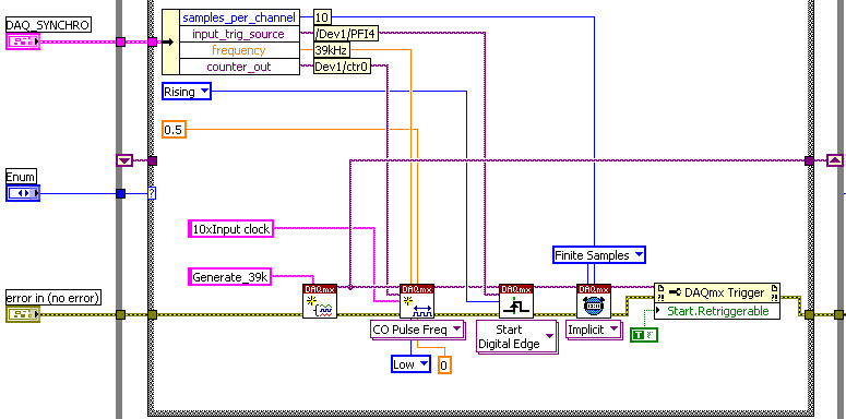
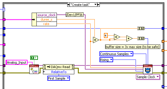
The accuracy of my clock of 3.9 kHz being much higher than what I have on the DAQ card, I thought that an interesting option would be to have a redeclenchables DAQmx task that generates impulses from 10 to 39 kHz for each pulse received from the clock and then use it to trigger the DAQmx AI task.
Of course this can only work if the 'trigger' sources that I defined for these two tasks do not take both counters that I have on the card.
So, let's describe the DAQmx tasks:
-Here is the one who generates the 39 kHz on 0, the counter of the 3.9 kHz I entered as a source on PFI 4 trig
-This is the task of analog input for which I put the trigger on 6 PFI.
It is: I have "softwarely" know the jury to deliver output (Ctr0) 6 FBP counter? And if so, how?
Thanks in advance for any help!
Maybe you missed something that I didn't really point out in my post. The method I described would use the external clock of 3.9 kHz precise as a sample clock, so you would * not * be in danger of loss of synchronization in 1 s per day. You need to only son of this clock signal in a stem of PFI available and configure the task to HAVE it as a result. The 80 + kHz clock that controls conversions within each sample cycle * would * be generated by the jury of 6221, but he don't would not accumulate any out-of-sync error because he gets "retriggered" on each edge of the 3.9 kHz precise clock.
-Kevin P
-
PCI-6221 PFI0 start trigger is stray signals reading
We have a card PCI-6221 attached to a SCB-68 in a control console, we've made dozens of times. However, this time, we will have problems with the beginning of PFI0 relaxation. Operation of the actuators 24 v remote (cable to DAQ card but operated through manual switches) triggers the beginning. We tried a shielded cable and everything is grounded. There is no parasitic voltage coming into the SCB-68 box. We sent also all the other analog I/o box. It's just the son of trigger start going. What is unusual, is that if we give a thread to the PFI0 (Terminal 11) who does not finish anywhere, we just hold in the air, do not cross any other thread, running our actuator valves still initiates the trigger. If we remove the wire, it does not raise. It's almost as if she receives wireless signals. But how wireless receives + 5V to trigger I don't understand. We also tried to use a spare PCI-6221, same known issue work. When you view the PFI0 in MAX, flipping the switch actuator will cause the counter generate 400 + charges. A normal release with our power switch usually generate 10-20-count indictment. We are really puzzled. Thanks for any help!
Don't have not an answer to the first question, will have to research.
THA Cabinet is wired the same, the only difference is that we added a transformer so that the system can run on the seas, but has not actually been hooked again, sitting in the Cabinet.
Yes, we used a cable leading to one end. We tried the ground at both ends, the same results. I also waved to the cable in the air and a people in the head with it, it made me feel better.
Don't think on the unused entries in the Earth. Personally, I think that the PFI0 is to be triggered with less than the + 5V, the scope is the very low voltage reading.
But I found a solution. I mentioned in the original post that trigger actuator, just once, causing 400 + edge detections/counts when viewing in MAX. It is a large number of charges in such a short time. So I programmed in a digital filter using a min pulse width. ".". 00256. Eliminating the 400 + short bursts of any signal. I used the example of filtering VI in this knowledge base article:
For those who have similar problems, there is no physical change, just incorperate of wiring of the filter.
-
Need help on the use of the PCI-6221 and c# to control three digital Port and an analog of entry
I need to send the digital output at three ports and then read an analog input voltage using the analog card PCI-6221.
I did a c# program to fight against it. I built four tasks altogether. Three tasks for three digital output ports and a single task for analog input.
How can I reduce the time?
Using my method, to 3.3ms in total. And it's slow.
I can build one task for three ports?
What is the best way to the control task to reduce the time of communication with the PC?
Is that possible to save a lot of analog reading entry in the memory of the DAQ hardware and then read it all together from the computer in order to reduce time consumption?
1 million thanks!
Hello
Hi Jin,
To answer your questions, Yes, you are able to configure a task of digital output to use three output ports and PCI-6221 has a buffer of memory FIFO aboard 4095 samples.
I would like to direct you to the example of NOR-DAQmx for c# files located in the following location on your computer
C:\Documents and Settings\All Users\Documents\National Instruments\NI-DAQ\Examples\DotNET2.0
Here, you will find predefined examples in c# that should give you a good idea of how to go about architecting your code to achieve the results you need.
There is also a useful help file which you will find by navigating to Start > all programs > National Instruments > NOR-DAQ > help of NOR-DAQmx .NET Framework 2.0
I hope that this answer is useful.
Best regards
Steve H
-
Selection of encoder to use with NI PCI-6221 for a project of inverted pendulum
Hi, I'm a mechanical engineering student is his last years, for my final project I do an inverse pendulum system, the University already offered me this data acquisition card which is a NI PCI-6221, and I have to get the other components (motor continuous, encoders, cables, servoamplificateurs, etc.).
My concern is to choose the right encoder so I have no problem... I was told that the best way to measure the position of the carriage uses an absolute encoder mounted on the motor shaft and some incremental encoders for measurement of angles of clock, but I don't know if the 6221 can handle this kind of data to an absolute encoder, and if so, what are the main parameters for selection? as the format, the number of bits.
In the case where it doesn't work I have to go with the option of incremental encoders for both measure the position of the carriage and the angle of the pendulum, I believe the 6221 can manage entries in quadrature encoders, there´re a lot of examples of this, but since models of incremental encoders are wide enough there´re some features that I worry about : frequency vs the sampling frequency response and the output type.
I found a catalogue which includes two types of digital incremental encoders said their models have 300 KHz frequency response, being the only differences, the output and food, anyway the 6221 can handle this freq resp? sampling rate of the card being 250 kech. / s, would there be any conflict?
They offer two types of output: TTL/74LS04 and line pilot, and even if I go further with the hohner encoders they have the following outputs/freq RESP: RS-422 (TTL compatible) / 300 KHz, push-pull differential/200 KHz, NPN Open Collector/100 KHz and push - pull without complementarity/200 KHz.
Any help would be well received

PD: I don't know if a similar topic has already been posted, I'm again like this... I searched in other posts, but found nothing,
-
The drift in analog of the PCI-6221
Hello
The VI described below makes the measurement of three analog channels. Then it calculates (if - then)
/ So B, where TR = Ai2 Ai1/channel channel
and Bi = channel Ai0
When TR = therefore, the average reading should be zero, but in fact what I get is the behavior showed in the chart below.
I use PCI 6221, BNC-2110 and LabVIEW 7.1.
This may be the cause of this drift? Could you help me fix this problem?
Thank you
Marcelo.
You see on a derivative of uV ~ 40 on the map ±10V range?
It would be nice in the care of the accuracy of the 6221. However, it sounds like the drift occurs over time. If you leave it plugged in long enough tensions continue to drift or they stabilize?
It could very well be that the battery voltage is what is adrift. However, if you add help polarization resistors so it is possible for you to accumulate small amounts of load on CDA - what values of resistance have you tried? You can also consider CSR and connect the terminals of the battery (-) ground HAVE common to avoid having to use polarization resistors.
Best regards
-
Find the strength of output voltage
My VI generates a graph displays the output voltage of two 250 lbf (http://search.digikey.com/us/en/products/FC2311-0000-0250-L/MSP6952-ND/809398) to load data sheet (http://www.meas-spec.com/downloads/FC23.pdf) cells. I am trying to determine how much force is applied to the my output voltage load cell. So basically how to convert the output of a tension force (Newtons). Thank you.
Sheet indicates that the nominal power is 100 mV at load full scale and 0 at no charge. If you neglect the mini-maxi offset of zero and span min - max variation, you have 250 lbf/100 mV. Then multiply by the conversion factor appropriate in newtons. To account for the offset and gain variations, you might use a linear correction by solving the equation of a line (y = m * x + b) at two points, one with and without load near full scale.
Some DAQ drivers put the scale included.
Lynn
-
On the NI PCI-6221 fast sampling rate question
Hi I was wondering if someone can answer a question of sampling rate on this card to PCI-6221 (http://sine.ni.com/nips/cds/view/p/lang/en/nid/14132).
Especially if I wanted to transmit simultaneously (analog output) and data acquisition (analog input), what is the sample rate max I could use. Kind regards.
Since the 6221 is multiplexing the analog input, your question for I / simultaneous ao is possible for one channel of the only. If your "simlutaneously" can include delays (e.g., 100us), you may be able to work with several AI channels as well...
HAVE the multiplexes, workable sample rate given that the total sample (250 kHz) frequency divided by the number of channels that you use. AO is faster than HAVE it, so it does not reduce this number.
hope this helps,
Norbert
-
5V power supply seems to have failed on PCI-6221
I recently had a test set-up down, and it seems that this could be linked to the + 5v supply.
When I connect 5v to the unit via an external power supply Board, the Board draws 50ma, far as the 1A, according to me, the PCI-6221 power is specified as being able to provide. When I connect the camera Board to the PCI-6221 via cable, only 0.67v are measured on the map. However, when the cable is not connected to the card of the unit, I measure 4.5V on the power supply 5v card PCI-6221.
I couldn't find a standard of accuracy for the power supply of 5v, but I expected to be less than 0, 5V. It seems that my PCI-6221 power can produce a voltage in open circuit, but decreases rapidly under a load condition, which seems that the jury didn't.
Ideas? Thanks in advance.
Hi Scott,.
Terminal on the 6221 5V is rail 5V PCI bus with some type of lighter, so the accuracy will depend on the computer's power. Would you be able to try this card in a machine that has a work data acquisition card? This would exclude any power problem on this computer. If this test fails, it is likely that there is a fuse and you will need to contact us as Josh mentioned for an RMA number.
Maybe you are looking for
-
Automatic filling of the order of the day
Hello I am trying to automatically fill in an 'order of the day"a"graphical task"as pictured below. When the date of the order of the day is changed, I would like to as tasks and details of my task card to automatically fill in the order of the day.
-
Wired Keyboard 500 does not properly
My new wired keyboard 500 ignores strikes unless I type very slowly. My old keyboard does the same thing. Very frustrating. Is this a Vista problem?
-
I forgot the password to unlock the laptop
I have a toshiba laptop, and when it turns on it will ask my password, I have donot have. I have the install dist but the computer does not start the disk until you enter a password. I can't even get into the home screen without password. I try not b
-
Ergonomic Sculpt the mouse wheel doesn't work do not
Hello When I use my mouse it works well. When I try to scroll, but my mouse is not responding. I can do the thing of fast scrolling by pressing the scroll wheel, but I can't really scroll. The keyboard works fine and the scroll wheel is the only thin
-
How do I abort or kill or cancel suspended adoption patch run? (EBS R12.2.4)
Hi allEBS R12.2.4OEL 6.5Check patches (adoption-status) without previous state, I applied a fix to help:phase of adoption $ = patch = 20059164 patchtop = / home/applcrp2/patch_for_applicationBut I got the following error:Successful validation. All ar