PCI-6221 PFI0 start trigger is stray signals reading
We have a card PCI-6221 attached to a SCB-68 in a control console, we've made dozens of times. However, this time, we will have problems with the beginning of PFI0 relaxation. Operation of the actuators 24 v remote (cable to DAQ card but operated through manual switches) triggers the beginning. We tried a shielded cable and everything is grounded. There is no parasitic voltage coming into the SCB-68 box. We sent also all the other analog I/o box. It's just the son of trigger start going. What is unusual, is that if we give a thread to the PFI0 (Terminal 11) who does not finish anywhere, we just hold in the air, do not cross any other thread, running our actuator valves still initiates the trigger. If we remove the wire, it does not raise. It's almost as if she receives wireless signals. But how wireless receives + 5V to trigger I don't understand. We also tried to use a spare PCI-6221, same known issue work. When you view the PFI0 in MAX, flipping the switch actuator will cause the counter generate 400 + charges. A normal release with our power switch usually generate 10-20-count indictment. We are really puzzled. Thanks for any help!
Don't have not an answer to the first question, will have to research.
THA Cabinet is wired the same, the only difference is that we added a transformer so that the system can run on the seas, but has not actually been hooked again, sitting in the Cabinet.
Yes, we used a cable leading to one end. We tried the ground at both ends, the same results. I also waved to the cable in the air and a people in the head with it, it made me feel better.
Don't think on the unused entries in the Earth. Personally, I think that the PFI0 is to be triggered with less than the + 5V, the scope is the very low voltage reading.
But I found a solution. I mentioned in the original post that trigger actuator, just once, causing 400 + edge detections/counts when viewing in MAX. It is a large number of charges in such a short time. So I programmed in a digital filter using a min pulse width. ".". 00256. Eliminating the 400 + short bursts of any signal. I used the example of filtering VI in this knowledge base article:
For those who have similar problems, there is no physical change, just incorperate of wiring of the filter.
Tags: NI Hardware
Similar Questions
-
How can I activate several tensions trigger on the PCI-6221 using NOR-DAQmx?
I use the card to make an acquisition of data simple PCI-6221. The idea is to allow three different analogue voltages trigger the State of data acquisition. I currently put code in place for a trigger voltage but I'm not sure what to do to add two additional trigger voltages. Any ideas?
Thank you.
Hi capncane,
The 6221 is not able to do an analog trigger so DAQmxCfgAnlgEdgeStartTrig will not work for your card. Is your relaxation a digital signal? If so what kind of logic level is? If it's TTL, you can use the PFI lines. If this isn't the case, you need to trigger as I mentioned in my previous post.
-
Hello
I want to build a program with card PCI 6221 multifunction. In the program, it generates two analog signals to trigger a CCD camera and turn on an LED. Meanwhile, program to acquire an analog signal for a specific duration, and images that are acquired by the camera must be displayed. Above activities in signal acquisition and generation happens to a user the period (the time is currently 1500ms) and the whole process is repeated 40 times. A while-time loop thus serves to launch the signal generation and acquisition and acquisition of streaming images.
Analog signal acquisition should start at a point that specifies the user and he should continue for a set period of time. This is currently done using a digital signal, created and use the port this signal as a trigger of break for AI System. However, all these signals generating and absorbing processors should be well synchronized and accurate at the time. An external clock is shared by all of the clocks used sampling in GOT it, AO and DO (CTR0). Literature, I realized that digital output cannot be triggered in the M-series card, so I use a system of internal release (as shown in the examples in LabView 2010 multi functions).
Question: Is there a good way to start the analog and digital output using another output signal (lets assume a signal generated by CTR1) each cycle in order to maintain a highly synchronized system. (I don't like running the timed loop sample clock and continues to HAVE it and AO).
The 6221 does not have a digital output timing engine, so you cannot trigger directly (or define a.) ReferenceClock, well it's not like that's what you want to do anyway). You can directly use a sample from another source clock, then this clock signal is what needs to be triggered.
I agree with software distribution is not a good idea - you can probably implement this with hardware timing instead, although I don't know how the camera fits into the equation.
I assume you are using CTR0 as an output meter finish, task redeclenchables. Then you use that signal as a sample for AO clock, and I? This is probably what you want to do. Finished Counter tasks require the use of two meters on the boards of the M series: DAQ, so you would not be able to use CTR1 indepdently of CTR 0 if you want to use the outputs of the redeclenchables counter finished. You can always generate 0 if you do not want any voltage output during the acquisition.
Best regards
-
measure the distance between 2 impulses (PCI-6221)
Hello
I have a digital signal that sends a pair of impulses (100ns width each) roughly every 100ms and I measure the time between two pulses of a pair (with a resolution of 100 ns).
For the moment, I got a card PCI-6221 to accomplish this task. Unfortunately, I have no solution until now only measures of counter, I found measure time between constant frequency signals, i.e. they cannot measure the distance between 2 single pulses.Any help / ideas / or even telling me that it is impossible to solve this task are appreciated
Are the two pulses on the same line?
If so, you need to just configure a task of the measurement period. If they are on separate lines, you would use a task of "separation of two-edge.
You might be to throw off by the timing of it:
If you do not configure implicit synchronization in your task, will start on the first edge after DAQmx Read is called. Thus, in order to intercept the signal, that you must configure your task, call DAQmx Read and then start your two squares.
If you want the task to control the signal continuously, you must configure name timing. In this case, you will receive a sample on each rising edge of the external signal (assuming that the two impulses on the same line) - If you start the task of counter before starting the production of pulses (which you probably should), then the same samples correspond to the time between pulses, the odd samples would be the time between each series of pulses.
More information on modes of counting on the 6221 lie in the M series user manual.
Best regards
-
Need help with counters on PCI-6221 (37-pin)
Hi all
I have a system with a PCIe 1429 connected to a Basler A504 camera and one I use a clock generator (SRS CG635) of 3.9 kHz for trig the image acquisition.
On the same system that I need to add a PCI 6221 37
PIN to acquire:-2 HAVE 39 kHz, synchronized with the acquisition of the image. (Sample of the 10 for each image)
-1 meter to measure a frequency
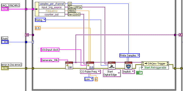
The accuracy of my clock of 3.9 kHz being much higher than what I have on the DAQ card, I thought that an interesting option would be to have a redeclenchables DAQmx task that generates impulses from 10 to 39 kHz for each pulse received from the clock and then use it to trigger the DAQmx AI task.
Of course this can only work if the 'trigger' sources that I defined for these two tasks do not take both counters that I have on the card.
So, let's describe the DAQmx tasks:
-Here is the one who generates the 39 kHz on 0, the counter of the 3.9 kHz I entered as a source on PFI 4 trig
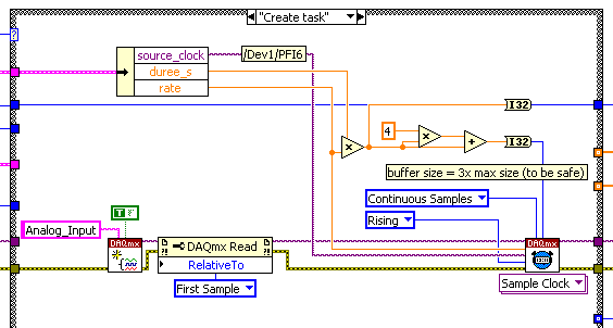
-This is the task of analog input for which I put the trigger on 6 PFI.
It is: I have "softwarely" know the jury to deliver output (Ctr0) 6 FBP counter? And if so, how?
Thanks in advance for any help!
Maybe you missed something that I didn't really point out in my post. The method I described would use the external clock of 3.9 kHz precise as a sample clock, so you would * not * be in danger of loss of synchronization in 1 s per day. You need to only son of this clock signal in a stem of PFI available and configure the task to HAVE it as a result. The 80 + kHz clock that controls conversions within each sample cycle * would * be generated by the jury of 6221, but he don't would not accumulate any out-of-sync error because he gets "retriggered" on each edge of the 3.9 kHz precise clock.
-Kevin P
-
How to send and receive a trigger on Labview signal?
Hello
I use a PCI-6221 card with a SCXI box to control a system.
I want to send and to receive a signal system which I use another system, which is not a system of NOR, to start and stop processes both sampling on both systems.
Someone knows how to do this in labview?
Thanks for your help in advance,
Its up to you. Which ever you feel is best. If you're new to it so better use assistant DAQ & then convert as in source code & learn things.
If you still need help, you can send the same.
Congratulations are welcome. Don't forget to close the thread of "accepting" the solution
-
Starting point for the signal clk sample
I am currently trying to synchronize my PXI-7344 Controller with my hardware DAQ-PXI-6221. The devices are connected through 1050 PXI/SCXI chassis.
I wrote a program on board pending a signal RTSI and then making a capture high speed. The data is buffered in memory and then transferred to the PC in chunks.
To synchronize this data with my DAQ data, I want to export the sample clock in the RTSI bus. My question is: the sample clock start sending signals RTSI after that I prepared and booked the task (the sampling frequency is known) or these signals do not appear before you actually begin the task?
In the latter case, it would be much easier to merge the data because the two devices were producing the same amount of samples.
Concerning
André
Hello Andrew,.
Clock signals are not exported through the RTSI bus, until the task starts unless the trigger is configured. In this case clock signals will not be sent until the start trigger is received.
-
Restart waveform immediately start trigger
I create a waveform 50 ms with an SMU-5451 in SMU-1078 chassis with a controller of SMU-8840 running Labview RT. The waveform is currently triggered by a pulse of a counter of data acquisition because the timing of the wave must be closely synchronized with data on the acquisition of data collection. However, this approach is problematic because it is difficult to produce a continuous of the 5451 signal when it is triggered in this way. If the waveform is exactly 50 ms long, will miss the start trigger. I can tolerate losing at the end of the wave, but I can't tolerate having a gap in the output, and I need the waveform to start exactly on the edge of outbreak of 50 ms. I can configure the 5451 to accept a trigger start and restart the wave immediately rather than wait for the current iteration of the waveform to complete?
I guess I could use a complete the 5451 event to trigger the acquisition of data instead, but I guess there is a way for me to do what I want.
Are you familiar with the mode "script"? You might be able to use this example script:
script restartWhenTriggeredScript

  Repeat forever

    generate wfm

    break on scriptTrigger0

      Repeat forever

        generate wfm

      end repeat

    end break

  end repeat

end of script
Basically, the idea is that, when it receives a trigger, it stops the execution of the inner loop and finish the iteration of the outer loop. Then it will start again from the beginning and to the inner loop.
Please let us know if that fixes the problem.
-
PCI 6221 generating an output voltage
Hi all
I'm trying to use a card PCI-6221 to provide a voltage of 5V analogue output and use it HAVE read the returned signal using labview. Anyone know how I can do this using this hardware device?
Thank you
Hi lrving9,
First you need the DAQmx driver, here is the link for you to install the latest version.
NOR-DAQmx 15.0.1
http://www.NI.com/download/NI-DAQmx-15.0.1/5353/en/If you already have it, so go ahead and take a look at this example:
It shows you how an analog DC output voltage.
Community: Output analog voltage constant
https://decibel.NI.com/content/docs/doc-18631So you have a block of connection to connect the signals?
If you do, then you can simply create a task to read a continuous voltage entry, as in this example
Community: - Input voltage
https://decibel.NI.com/content/docs/doc-25105If you do not have a connection block and have no way to connect the OD to HAVE, then you can read the inner channel of AO, as shown in this link (there is an example at the bottom):
It is Possible to read the value of the digital or analog output channels?
http://digital.NI.com/public.nsf/allkb/CB86B3B174763C3E86256FFD007A2511Also when you install the driver a few examples are installed as well, this shows you how to get them:
Where are the examples of NOR-DAQmx installed?
http://digital.NI.com/public.nsf/allkb/E3BAF6FC4017960B8625755A00525D37Kind regards
Caroline
-
Triggering of a task by using PFI on a Board of PCI-6221 (37-pin)
Hello everyone,
I need material triggered acquisition, use of the PCI-6221 (37-pin) card board. In LabView, I used the simple program (see attachment): in a data acquisition assistant, the start of the task is set to 7 PFI. However, to make a PFI7 pulse does not trig acquisition and I get timeout error.
When I test the same, but using the standard PCI - 6221 Council (i.e. 68 pins), everything works fine.
I have to do extra to PFI configuration when I use the Council 37 pins? (Note: the same PIN is assigned to the PFI7 and digital line P1.7).
Thank you.
Jiri
P.S.: I use LabView 8.0, OR-DAQmx 8.7.1 and Windows XP Professional.
Problem was curious, but it is solved now:
-OR-DAQmx wasn't actually 8.7.1 8.0.0; I have updated (but it still didn't work)
-J' replaced the virtual channels by the corresponding physical channels; He began working
-J' replaced return physical virtual channels, and it works always :-)
It seems that there is a bug somewhere in OR-DAQ.
Jiri
-
PCI-6221 behavior off the power
Hello
A card PCI-6221, tension of the PC is out of snap-ins:
When I inject a voltage (5V) input ana on the map, this tension is copied on the other analogue channels.
Room I turn on the PC, and 6s after, injected tension is more copied on the other tracks of ana.
What is the normal behavior of the map?
Thank you pour your answers
Hello Cedric,
The behavior of the card when it is turned off is not defined. What is it you have a problem in your application?
When you area PC, this one seems to provide power to the bus PCI 6 seconds after it starts, which explains why the map then adopts its operation.
The best advice I can give you is to respect the configuration/connection of analog input (manual page 58 Chapter 4-14 M-series cards). About the card, if it works properly when the PC is turned on, and that the connection am well the guide, there is every reason to be reassured.
I wish you a good day,
Marc-Junior
-
Need help on the use of the PCI-6221 and c# to control three digital Port and an analog of entry
I need to send the digital output at three ports and then read an analog input voltage using the analog card PCI-6221.
I did a c# program to fight against it. I built four tasks altogether. Three tasks for three digital output ports and a single task for analog input.
How can I reduce the time?
Using my method, to 3.3ms in total. And it's slow.
I can build one task for three ports?
What is the best way to the control task to reduce the time of communication with the PC?
Is that possible to save a lot of analog reading entry in the memory of the DAQ hardware and then read it all together from the computer in order to reduce time consumption?
1 million thanks!
Hello
Hi Jin,
To answer your questions, Yes, you are able to configure a task of digital output to use three output ports and PCI-6221 has a buffer of memory FIFO aboard 4095 samples.
I would like to direct you to the example of NOR-DAQmx for c# files located in the following location on your computer
C:\Documents and Settings\All Users\Documents\National Instruments\NI-DAQ\Examples\DotNET2.0
Here, you will find predefined examples in c# that should give you a good idea of how to go about architecting your code to achieve the results you need.
There is also a useful help file which you will find by navigating to Start > all programs > National Instruments > NOR-DAQ > help of NOR-DAQmx .NET Framework 2.0
I hope that this answer is useful.
Best regards
Steve H
-
I use pci-6221, I need her to interface with thermocouple with voltage up to 5v
I use as my pci-6221 or data acquisition card and card 8.2.this labview version gives the constant 10.5 volt signal in at the entrance to analog channel AO on pin 68 and 34. why it shows 10.5 although I did not connect any input.i use type k thermocouple and after signal conditioning with tl0804 I need it interface with AI 0.i channel unaware aware of off the road on the output pins this Card.i need to operate an electric rod that needs 24 volt DC.i give entry to the pins HAVE with variable dc power block after reaching the limit I set(eg:2v) it jumps instantly to 10.5 volts.
You have your task to acquisition of data configured for the mode differential or asymmetric acquisition for the analog input?
I don't understand your comment about to connect the pins WITH a DC power supply. Why is that you connect a DC power supply to the analog input?
Using an analog output or digital output to operate the electric rod? I'll assume that you are looking for on/off control. A digital output is not the voltage or current to drive something that big. You may be able to find a relay for coil 5VDC. Check current requirements. With which you can have the relay to connect or disconnect a power supply of 24 VDC is the actuator. Make sure you have a protection diode across the relay coil wired, so that the magnetic field of the coil does not damage the analog output of your card.
Another possibility is to have the 5 VDC output transistor circuit switches the 24 VDC circuit.
-
SC-2345 misconfigured and PCI-6221
Hi all
I have the following configuration:
Windows XP
OR PCI-6221 (68 pins)
SC-2345 (several modules installed: 4 x SCC-TC02 in J1 - J4, 1 x SCC-CI20 to J5, SCC-SG24 to J6 1 x and 2 x AI04-CSC J7 & J8)
LabVIEW 8.0
NOR-DAQmx 8.1, MAX 4.0.3.3
My card PCI-6661 passes its self-test and seems to be fine in MAX. My SC-2345 carrier seems to work (the power Board - CSC-PWR02-LEDs light up). I configured the SC-2345 and CSC modules by the manual, click on 'OK' to save the configuration to MAX. but when I try to run the test panels on clusters to copy single (all except the NCC to power), I get this error (same for each CSC, although 'the physical channel name' changes for each):
200170 error occurred at the test Panel
Possible reasons:
The physical channel specified does not exist on this machine.
Refer to the documentation for the channels available on this device.
Device: Dev1
Name of the physical channel: ai0I'm baffled at this stage, so any help/pointers would be great, thanks.
Hi Luis,.
Thanks for the reply. I do not end up installing a newer version of DAQmx, although not later (when I tried the latest version, I ran into issues with screws in my old version of LabVIEW). I ended up going on the way to upgrade DAQ after reading the manual PCI-6221, who has taken on DAX 8.7.1 or later, so I installed 8,71, and who finally solved the problem.
Interestingly, as far as I can tell MAX, the system is exactly the same; somehow under the MAX, the software of data acquisition software is to connect the dots for me.
Thanks again,
Dan
-
analog calibration on PCI-6221
I don't get the volts per bit, I expect my Board of PCI-6221.
I run the "Test Panel" available in v.4.3 Measurment & Automation Explorer. I have a NOR-6221 multifunction with an installed interface BNC-2090 case. When I run the "analog input" test, with entries dfferential and connected to ai8 ai0, I expect to 0 volt. The input values, the min max run defaults to-10 V + 10 V. The graph shows zero + - 1 to 2 bits of noise. See screenshot. The reported real amplitudes are + 0.000468, + 0.000144, - 0.000180, - 0.000504. This corresponds to 0.000324 V/bit. I expect to 20V / (2 ^ 16 bits) = 20V/65536 bits = V/bit 0.000360. How to explain that gap of 10%? Thank you.
Bill
Hey Bill,.
I could see a few things: with the M series, realize that the data returned by the ADC are not linear, so that V/bit varies over the range of the acquisition. Mcal allows us to correct the non linearity. Which may explain the discrepancy just here. Also note that the range is actually greater large - to make cal the range desired, some codes are outside the range of V 10 - generally of 5%. However this would actually push the V/bit upward. This is mentioned in the M-series user manual in the section of the analog input range . All this is taken into account absolute accuracy specifications so that they are still valid.
Finally, when I calculate 20/65536 I obtiens.0003052 - which, once I multiplied by 1.05 gives moi.0003204, which looks a lot better. You may have swapped the 6 and 5, or the Windows calculator is fibbing to me once again

So this brings me to my question - you notice the difference just theoretical vs measured and I was wondering what is happening, or you plan the use of this info? If you are looking to read binary (a common practice results in questions like yours), take a look at this KB when you get to the scale of calibrated data-
3SKGA409 Ko AE: is raw data DAQmx calibrated and/or scaling?
Hope this helps,
Andrew S
Maybe you are looking for
-
backup of diaphragm open with wrong version
Hello I have 3 backup opening and I want to open it, but I get the message: "You have a more recent version of the opening, please convert the backup of that version. How can I know which version of the backup was made and convert? or How can I downg
-
Satellite L655 - CD/DVD TS-L633C burning questions
Hi all I have a portable Satellite L655, I bought a few months ago. The problem I face is now with my DVD player. When I try to burn a DVD using Nero Vision or any other burning software, even if he says he burned and successfully completed the rest
-
downgrade from victory 8 to win 7 on a HP Pavilion A8 (E055nr)
-
Tektronix AFG 3253 USB question
I'm having some problems with running a test of long duration (100 + hour) with a Tek AFG 3252. I was using a converter USB / GPIB to communicate with him. For some reason any USB port down and he refused to communicate after that and the settings
-
I can guess that relates to all the questions that I have as follows; These are being administratively and come in last in the top seven, they are not here in perfect order I jumped on a couple. I understand that these contained the most critical new