problem of Modbus
Hello world
I'm trying to contact card ADAM 4024 (4 ch analog outputs). I use the Modbus communication. Please check the error Image I receive.
Please explain the reason for the error.
Thank you in advance.
Hi LV_pro,
Thank you for your response. It was very stupid mistake. The card has been configured for the "ADVANTECH" Protocol  . I changed it to MODBUS then my program is very well executed.
Thank you once again.
Tags: NI Software
Similar Questions
-
Problems using Modbus TCP accessible by NI OPC Server
Hello
I use OPC OR server to access a module of measure. The accumulation is pretty easy, my system with NI OPC, modbus door and the module connected with RS485.
There is a thermocouple to provide me with some examples of data.
But there is the point. I know, my data is in the records to be kept and I can access, but each type of data, I'm train does not bring my outgoing, any other (sometimes huge with e34, sometimes very small as e - 13...) my data sort, I do not understand.
The type provided by the module must be single precision.
The address used to be lookout is 41000 Labview in is just 999 and in the 'target' - OPC Server I get some values to 401000 but not useful.
I also get the same results to access the 301000 into different types.
Read/write or read-only is equal.
I tried to tell my mutual FUND values are strings, floats, words, BCD, and all other possible means what mutual FUNDS offered to me, but nothing results in a usable temperature.
I hope that I missed something and it might suggest.
Cateros
Finally, the issue is resolved.
We tried a few others setting for the device in NI OPC modbus Modbus function 06 use simple written record. Using the Modbus 05 functions for single coil written and use default Modbus byte order.
These parameters were not default and I tried some combinations but bad not these.
As the tag data type, we tried anyway and got the content of the Register Holding data [0].
Now it works, and the value is the casting of Holding register [0] and [1] Holding and I got the temperature.
Already you are quite right, thanks again.
Cateros
-
Error executing ethernet modbus slave demon in an executable
I wrote an application that integrates a modbus ethernet slave - similar to that included in the examples of LabView (2013). If I run this as a VI, then there is no problem. However, if I create an executable file then I get an error message on the version of demon slave being too old to convert it into 2013 version 8.6. I use NI Modbus Library 1.2.1 and the 86 folder.
To isolate the problem of modbus to my initial request, I took the slave example LabView MB Ethernet (2013) and launched a project which includes the demon slave vi and the vi.lib modbus 8.6. I changed the path to the slave demon in the example of the slave so that it points to the location of the slave vi demon in my project. If I build the application and run it I get a slightly different error - "the demon slave vi is not executable.
I don't understand why the demon of the slave will not run an exe program but will be in a VI.
This error does not much sense. LV 2013 can certainly open and run LV8.6 files.
You said that the executable file it who gives you this error. When you run this executable? It is on the same PC, you have developed and created the .exe on? Or another PC?
I wonder if you run it on another PC, you do not have the runtime engine proper installed.
In addition, once you moved the VI Modbus to your most recent LV2013 environment, you've been through and mass compiled this library?
-
Hello Forums or
This is my first post on this forum and I've been using labview for about 8 months now
I have a problem about writing data in the modbus registers through a server of e/s defined as a slave modbus for my hardware 9074. Once I finished the project of construction and deployment of the variables and by following the instructions here , he reports no results but a row of zeros. I have the DSM nor opened and configuration modbus master to see whether the data is actually read or written on the respective sides that give the same line of zeros so. What I am actually trying to write is a single-precision floating data table. The registers are structured F40000-F46534 runs from 10 items or have them for range AF40001L1-AF46534L1 of the AF40001L10 point where it's an array of length 10. (Referenced beaches here)
I know 1 thing for you, the modbus connection works and is ready for data requests, I tested cela NI DSM and set manually the data for and received my master.
System and project specifications
Windows 7 operating system
LabVIEW edition development system complete 2011
No module Labview DSC, but I use the real time such referenced by one of the documents
This project is an application in real time with fpga mode (and not scan interface)
The master and the slave are the same network and subnet
Connection Modbus type: TCP
9074 compact slots rio 8
9234 module x 3
module 9221 x 1
9472 module x 1
Engine service Variable shared running on windows os and rtos system
Used this guide to learn more about the Protocol modbus, as I have searched all over the internet to learn more about modbus
I already have software Modbus IO Server installed on the crio thanks to max or 1.8 for NI RIO 4.0 version
file attachment (s)
Image of software specifications Crio
Image of data written in scheme-block rt variable
Short version of the problem: why is the e/s no variable writes in with the converted correctly data?
Okay, Yes, it's that I was the one proposed. Regarding the news of the error, if you look at the bottom of your image to DSM, you see a little commfail and an error code, but it seems that those are OK.
The only thing I can think is that DSM (or another function) is written for a range of values that includes 400004. I suggest you to put into service 4-going to a range of 3. 3 s are entered only (perspective control), then you can be sure that the master is not trampling on the data. Once you have checked that, look at DSM and any other code running to make sure q EU not accidentally write 0s to the same reg.
-
Hello
I am trying to contact a Watlow F4D controller on a room using RS232. I use a cable converter USB-series and NI Watlow F4D Serial Driver.
The code of error-1073807339 occurs in:
Read in F4.lvlib:Utility MODBUS RTU Watlow VISA receive message-> Watlow F4.lvlib:Utility Register.vi reading
I don't know what caused the problem. I am able to see the cable converter USB-Serial OR max. Please see the pictures for more details
Thank you
Felix
-
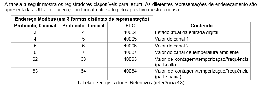
MODBUS RTU - problem reading Holding - myPCLab Novus records
Hello
I've tried for a few days to read the logs at Novus myPCLab (it uses the Modbus RTU Protocol). I used the DSC module both Modbus Library without success (it seems to connect properly but cannot read).
I need to read the given current.
Does anyone have an idea on what am I hurt?
Here's my vi and modbus address.
Through the DSC
I used the address PLC to 'HR Inicial' and 1 'St number.
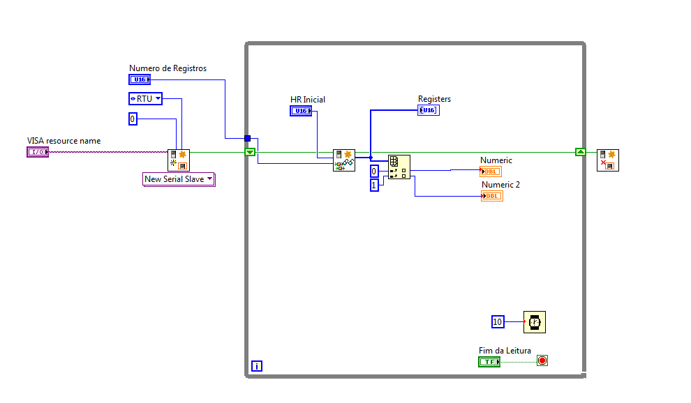
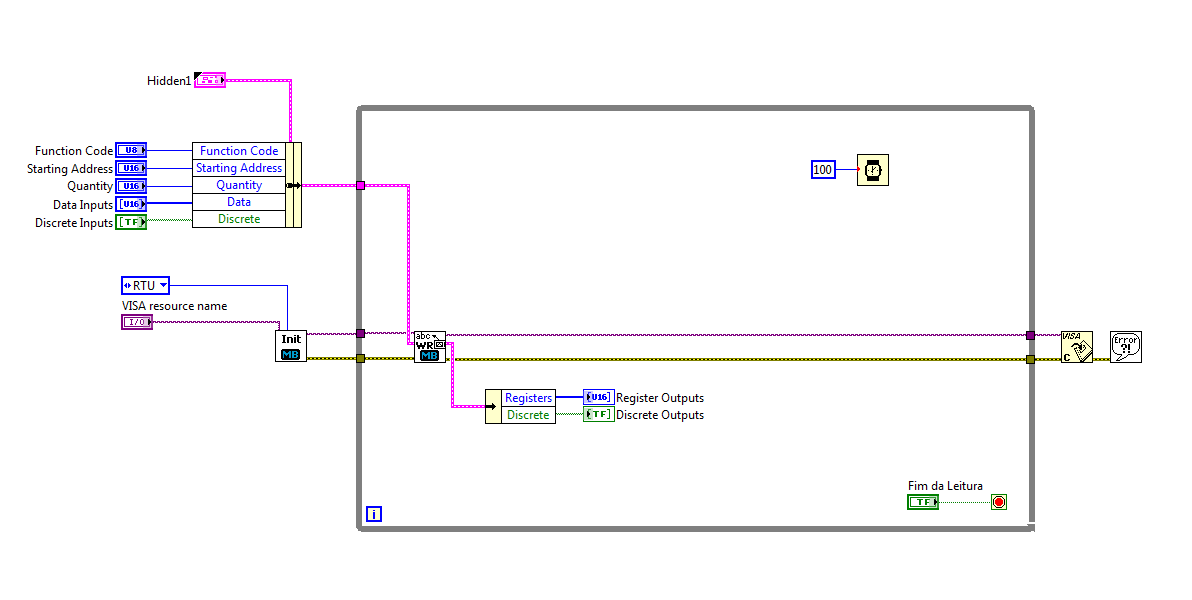
Through the library
I used the PLC address in "start address".
You have created a connection that is configured to use a "unit ID" 0. Slave never devices typically use a device number 0 which is considered to be a broadcast address.
Check the address of the slave of your device. So make sure that you use this number.
I guess that you communicate with a device that behaves like a slave. If so, you must create a Modbus master in your code. With the new modbus communication protocol Subvi, you created a slave. A slave cannot talk to another slave.
Similarly, in your second picture when you use the older Modbus Library, you not connected any constant to the top of the SubVI WriteRead that defines the parameters of series of devices such as RTU and address of the slave, so she takes by default to 0. Once again, a broadcast address.
-
Modbus tcp 1.2 problem with labview 8.5
I have a new upcoming project that involves a link to modbus tcp. I downloaded version 1.2 of the modbus library and installed. Everything appears on my palette, but if I try to open one of the examples he comes as for version 8.6. I am currently using 8.5 but the download says it works all the way back to 7.1. Any ideas?
Are you sure that you have selected the correct folder for the "installation"? When you download the 1.2 OR Modbus Library (here: http://zone.ni.com/devzone/cda/epd/p/id/4756), you get a zip file. Inside this file, you will see 4 folders, one for LabVIEW 7.1, (issue 71), one for LV 8.2 (case 82) and also records 85 and 86. So make sure that you have done the installation with the correct folder.
Let us know if this helps or not.
Kind regards.
Robst.
-
Problem of Lookout 6.0.2 modbus rtu?
One of our clients has Lookout 6.0.2 communicates with several Packs of Scada CMI on wireless modems using the Modbus RTU Protocol. All of a sudden Friday night he got comm fail alarm pages on site all but one. The Modbus statistics window revealed that Lookout had stopped voting for all sites, except a single site that remained in communications. The only activity is a single site.
He saw it queries this way for 2 hours, never to regain the normal polling cycle.
I had him quit and relaunch Lookout and mark returned to normal and has been like this since late Friday night.
This system has been in use for several years with very close 100% good communications sice we have deployed so far.
It was obviously a Lookout failure, since the only approach was to quit and relaunch Lookout.
Is there a timer for this kind of mistake?
Is this a failure of the cbx Modbus object? (We use the plain vanilla Modbus driver)
Roger Foote
Foote control systems
-
Hi all
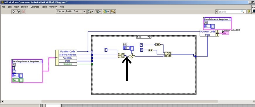
We try to add 20 saving file read function code in order to read the brief in bulk from PLC. We used the modbus for Labview library to communicate with the PLC with Modbus TCP/IP, but when I addes the code function 20 to the cluster of the MB Ethernet Master query entry reading registry Palette entry, the program displays an error. I'll be really appreciated if someone could help with this problem!
We hope all have a good weekend.
Best regards
Sophie
Actually... that is a constraint on the second entry to "build the table? ' It is difficult to tell from the image. If so, what is the data type of this cable?
That must be an array of U16s, because the "quantity" and "home address" are U16. However if the value '1' is a larger data type as U32, labview perhaps at upconversion of the whole table that would result in a larger data set than expected and could cause error 2. You can check on this?
-
ComBox MODBUS - difficult to write in the registers of the S.R.I.W.
Hey guys,.
I'm talking to a UPS (ComBox XW +) via MODBUS TCP. I can read the values of read only registers very well, and they line up exactly what I see on the interface of the web page they have. However, when I try to write a particular register r/w, I get an error of the incompatibility of function (-538172 using modbus smithd API). Also, when I try to read the register R/W, I always get the value 65535. This leads me to believe there something wrong with my configuration of device, but just in case, I thought that I would make sure that I wasn't doing anything weird in the code. Please the the image of the block diagram, as well as the manual that I use for the device in the attachment.
There is a small note MODBUS online as well:
http://solar.Schneider-Electric.com/wp-content/uploads/2014/04/conext-TL-using-Modbus-application-No...Hey Thomas!
Thanks for your help, however, this link is not available more when I try to open it.
In any case, this problem is resolved. I was just writing the bad slave ID! The other slave was present on the network, but it is card MODBUS is completely different, that's why I was seeing these weird values.
-
I have a sending oven that uses the Protocol No. 3, which communicate using Modbus over RS485. I use the Modbus Library, I found the Forum and I'm still with the controller communication disorders. I use a USB RS485 converter and my converter is set to half duplex 2 wire without echo. I'm able to convey, but receives a message back from the oven. Does anyone have any experience or any idea on how to use LabVIEW with this equipment?
I thank you for your response, we found the problem and the oven came to us by cable to the rear, this is why we could not communicate. We communicate now

-
Exstance no of Modbus communication
I work with a rs232 for connection rs485 via a UNO2019 PC box. The RS-485 connection is going to be MODbus RTU, has about 4 slaves on the bus (MMI flowmeter, VFD, two temperature RTD). All theses devices are configured accordingin
9600 baud, odd parity, no flow control. the VISA resource would be COM3.
Now all of these components I worked with every day for numerious months. and VI implementation exists (almost) without error. I get an error code for the additional bytes to the port, but he spends the whole upward. I don't know if I'm not or write, but it has happened in every piece of software, I developed in labview (it does not check the boolean error so I guess that's not important).
Currently, when I try to read the registers of the MODbus slave, I get error:
-107380733 (that mean 100 different things that I have done my research properly, bad bytes to the port, do not use correct end characters in your message). But every time I have seen that error code discussed in question direct USB/RS232, not RS232 to RS485.
The attached string was
3-> MD series Master Query.vi
2-> MB series Master query Holding Register.vi
1-> address Test.vi
Thank you for any light you can contribute on my problem.
Problem has been resolved. It was a hardware problem as I thought. Apperently this code error will exist when your RS-232/485 is hard set via dipswitches do not send data.
-
Point of Modbus DSC read does not correctly
I use 2013 LV 32-bit on W7 64-bit. I talk to an industrial controller with Modbus to Ethernet. My current software uses the interface modbus DSC, in which I define the bus Modbus itself within a library in the project, and then set each point Modbus as an address within this definition of modbus. Inside LabVIEW, you can then get the data Modbus via shared Variables. I am currently using the dynamic variable calls shared, rather than static variables shared. I have points that are Boolean (coils) and real, with a read-only and a read/write. In general, it all works.
However, there is a real read/write that acts funny. If I put a new value, or the industrial controller assigns a new value, the industrial controller Gets the new value. Variable motor shared on my computer gets even the new value, as can be verified by opening the Distributed System Manager. But LabVIEW continues to read the old value, without error. Other points of read/write work very well, and I have looked on the definition of the address several times and cannot find any reason why this should be different than the others.
Does anyone have any ideas why DSM sees a new value of a shared variable, without LabVIEW continues to get the old value? I watched the init for the dynamics of SV case, and I see all the options I can change to try to solve this problem. My next attempt will be to rewrite the entire auxiliary system so that it uses the most recent Modbus Library of NOR and ignores the whole thing of DSC. It will be probably much better for other reasons as well. I noticed that with DSC and the shared Variables, the first time that the program runs it starts fairly quickly, but subsequent executions can take up to two minutes to connect to the SV.
Thank you
DaveT
Never mind. I think I found the problem. A bug minor configuration in my own code...
-
Hello
Currently, I can read data out of multiple using the attached VI DAQ devices by manually changing the address of the slave on the front panel that determines what slave to read the data. However, I want the VI to do it automatically for me instead of me manually by clicking on the buttons on the front panel to change the address of the slave. In other words, the VI should read data off devices 3 slaves and save them to a database of all the 1 second (sampling from 1 sec interval). I tried to use the structures of the case, timed sequences and delays, but I'm still not able to get what I wanted. My current VI is a modified version of a VI library modbus - 'MB series Master query read input registers'. No idea how to do this?
IM pretty new to LabVIEW, so don't kill me if im away here
Could replace the cluster 'Series settings' with the attached structure solve this problem?
The real deal will be just the value back to the default (1).
-Tom
-
I use the MODBUS library and can receive data, but I can send it very well?
Hello
I use the Modbus Library to communicate with a VFD to control a fan. I use the master write and read vi. I can write data to the drive mechanism and get the fan to do what I want. The VFD is supposed to send a package of confirmation after I told him to do something and I can also read its records. When debugging the VI it shows that the problem is that the buffer always reads zero and the VI timesout. If I look at the USB adapter lights to RS 485, I use to interface with the drive mechanism, I see that the flashes of light RX immediately after I send a message. So I should have something in the buffer. Does anyone have any suggestions?
Aaron
OK, here's what has happened to those who have this problem. In the series Receive.vi MB The bytes to the Port of property node has been reading 0 even if there was something in the buffer. Executing the program was then stuck in a loop until it expired and never went to read anything of serial port buffer. I didn't spend too much time wondering why that VI has not worked and created my own. Within a period appropriate after writing to the serial port, I used the same bytes to the Port property node and was able to get the exact number of bytes to the stream and then VISA vi the number of bytes to read. I received the message of the right answer and everything seemed good. But of course that NO! Then I experimented with different speeds of writing to the drive mechanism to get the fan to operate at different speeds. I found a small range of speeds where I get no response to the VFD, either in operation or by sending me a response packet. After a while, I found that there is a mistake in the LRC-8 code in the MODBUS library OR. It does not prescribe that the LRC will be a two-character value. So if your LRC is proving to be a single character such as F value (which should be 0F) you get an incomplete MODBUS message. This has been easily corrected in the vi LRC8 saying "number in hexadecimal string" vi to produce output with a minimum width of two. Then everything worked fine. Moral of the story, it's the MODBUS library is awkward.
Maybe you are looking for
-
I have a SL6FA in it which can update it please. Thank youDave
-
How can I uninstall the free version of mackeeper?
I installed the free version of MacKeeper and want to uninstall it. Help! Any ideas?
-
Hello! I need help and consultation on the upgrade of RAM on my HP pavilion dv6-3125er (XW135EA #ACB). I have a RAM - 1067 MHz Samsung 4 GB SODIMM. I bought a SODIMM DDR3 PC10600 1333 MHz Kingston 4 GB. After that I put it, my laptop does not light.
-
How to convert the array of integer to string
Hi, I'm trying to convert the table of 32-bit integers to a string. For ex: If the array contains {1234, 4567, 8, 9} I need string like {00.00, 34,12, 00, 00, 45, 67,...} How to do this one. Help, please Thank you best regards &,. Harish. G.
-
How to return to the previously posted question?
How to return to my question already posted on this forum?