Problem of Lookout 6.0.2 modbus rtu?
One of our clients has Lookout 6.0.2 communicates with several Packs of Scada CMI on wireless modems using the Modbus RTU Protocol. All of a sudden Friday night he got comm fail alarm pages on site all but one. The Modbus statistics window revealed that Lookout had stopped voting for all sites, except a single site that remained in communications. The only activity is a single site.
He saw it queries this way for 2 hours, never to regain the normal polling cycle.
I had him quit and relaunch Lookout and mark returned to normal and has been like this since late Friday night.
This system has been in use for several years with very close 100% good communications sice we have deployed so far.
It was obviously a Lookout failure, since the only approach was to quit and relaunch Lookout.
Is there a timer for this kind of mistake?
Is this a failure of the cbx Modbus object? (We use the plain vanilla Modbus driver)
Roger Foote
Foote control systems
Tags: NI Software
Similar Questions
-
Hello
I am trying to contact a Watlow F4D controller on a room using RS232. I use a cable converter USB-series and NI Watlow F4D Serial Driver.
The code of error-1073807339 occurs in:
Read in F4.lvlib:Utility MODBUS RTU Watlow VISA receive message-> Watlow F4.lvlib:Utility Register.vi reading
I don't know what caused the problem. I am able to see the cable converter USB-Serial OR max. Please see the pictures for more details
Thank you
Felix
-
MODBUS RTU - problem reading Holding - myPCLab Novus records
Hello
I've tried for a few days to read the logs at Novus myPCLab (it uses the Modbus RTU Protocol). I used the DSC module both Modbus Library without success (it seems to connect properly but cannot read).
I need to read the given current.
Does anyone have an idea on what am I hurt?
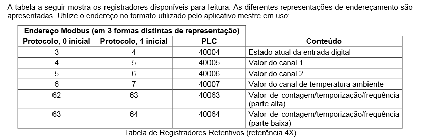
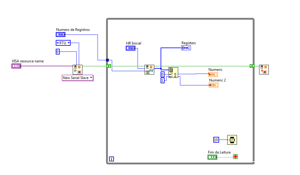
Here's my vi and modbus address.
Through the DSC
I used the address PLC to 'HR Inicial' and 1 'St number.
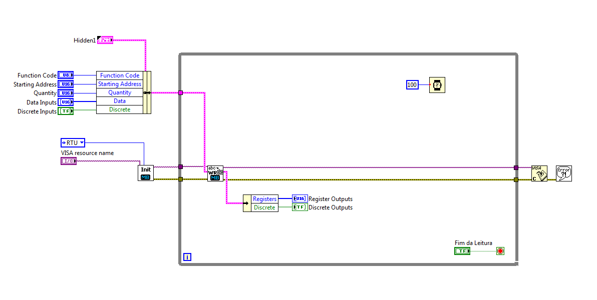
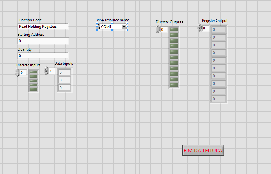
Through the library
I used the PLC address in "start address".
You have created a connection that is configured to use a "unit ID" 0. Slave never devices typically use a device number 0 which is considered to be a broadcast address.
Check the address of the slave of your device. So make sure that you use this number.
I guess that you communicate with a device that behaves like a slave. If so, you must create a Modbus master in your code. With the new modbus communication protocol Subvi, you created a slave. A slave cannot talk to another slave.
Similarly, in your second picture when you use the older Modbus Library, you not connected any constant to the top of the SubVI WriteRead that defines the parameters of series of devices such as RTU and address of the slave, so she takes by default to 0. Once again, a broadcast address.
-
need help on modbus RTU: do not know the meaning of the other output registers
Hi all
I use LV 8.5, a programmer time & 1st novice LV to post msg in discussion, so please let me know if I missed something important.

In any case, I'm 2 power meter data acquisition (1st is CPM-50 model, 2nd is MWH - 10, the two brand ADTEK). the Protocol of these devices are modbus RTU. I have two targets to:
1 acquire data using RS - 485 (portable <-->meters of power)
2. acquire data using ethernet (laptop <-->converter series/ethernet <-->meters of power)
now I'm in the 1st part, I use the local brand USB-RS485 converter & I think that there is no problem in the port itself (past the loopback test). I create a program using LV samples Mo using w / these port settings: 9600, 8, N-1 as databit baud, parity, stop bit respectively (the same data format of the device: see page 17/42 of the manual). I use the query.vi series of MB that I customized to eliminate the error timeout 6101 (see attached photo).
Problem: I can read the right data into the output register , but is located in the 5th element of the 1 d array. In the peak of the attached example, I'm currently reading the baudrate of the device (see manual pg 26/42: address 0102 h = 258 d). so I read the 9600 w/c is correct. I also had the correct readings of other addresses of parameter which is also located in the 5th element of the 1 d array. Note: I never tried to read data from power because the meters are not yet installed in the cabinets of power (maybe installed nextweek leave)
Question:
1. What is the significance of the first four output records in my table 1 d of output?
2. why I got 5 output registers eventhough I'm asking only 1 quantity?
3 read the correct data in the 5th element normal?
I want to just be deleted in the data I read before jumping in part 2 (connection via ethernet). If I forgot some valuable information, let me know. Thanks in advance!

Kind regards
Ivel
-
Dear all
I'm looking for a Modbus RTU on example TCP/IP VI. Does anyone have experience with this Protocol?
Please kindly give me some advice!
Thanks and greetings
Luong.Tran
Hello
Start herefor more information and the LV ModBus lib.
Kees
-
Protocol Modbus RTU data types
Hello
I use series ADAM with the data type Modbus RTU protocol.which should I use to read and write operation?
-
MODBUS RTU multiple request & response (OR VISA)
Hello
I would like to ask how many request and response on MODBUS RTU using VISA? I tried 2 camera digital surveillance, I did a Labview program to connect this device alternately using stacked sequence Structure, but it can communicate with 1 device and the answer, I think that there is an error, the number of bytes does not match what I ask (0 A 04 0000 0002 B 70-0)
It's my screenshot
any suggestion? or maybe use other way to many request and response use NI VISA?
Thank you ~.
It was pretty hard to see this video.
Of course, as part of the 2nd, lower comparison was coming to True, which means the false cases where things was spent could not run. (Seems like the reverse logic to me.)
Well, you check the first two bytes to see if they were not equal to 010 a. They were good because it is the response to the command you send who left 010 a.
In the first picture, it worked because you send the command from 0A 04 and compare to see that's not equal to 0404, which of course is not. What is the point of this? It makes sense to mixed. You want to confirm it is the correct slave address and the correct command (so that they would be equal) to run the code of decoding.
The other comparison is also useless because you try to check if the first two bytes are equal to 0 a, (any image you're in) which they will never because a string of bytes 2 can never be equal to a 1 byte string.
Through execution of high point, you should have been able to understand what was or wasn't running and why.
In addition, you only need a VISA close because you open just a resource of VISA.
Really, you'd be better off using the Modbus Library.
This is a much cleaner version of your code using the Modbus Library.

-
Is MODBUS RTU - always necessary to convert 2 * 16-bit to 32-bit?
I have spent a lot of time on forums try to solve this problem, and as of yet I have been unable to
Fix it.
I am reading a sensor of Carlo Gavazzi DC Modbus (programming manual attached) and were
getting a mixture of correct and incorrect values when reading from the device.
I use the library Modbus Labview who reads 16 bits of the default individual registries and what has
in general, been very well unless all negative values are involved. My access to each register method is simply
a loop by using the Example2_VI and iteration records required.
I am mainly interested in the following
Address:
 arameter::Register Value::Expected value
0::voltage:476: 47.6V (that's okay)
1::voltage:0:
4::current:65446:A couple of (negative) amps up! No 89 / 6500 a
5::current:65535:
Negative values do occur when the system (generator) is not running. When it actually works
the current 16-bit values can vary from 40 a to 250 a, but they are all incorrect by a factor of at least 10 to 20%.
I tried to use the example of vi to combine the current values in some way to return anything meaningful, but
whenever she repeats just NaN (not a number, I guess) so I'm wondering if I should make some sort of calculation
before I feed them in the type cast?
Try this.

-
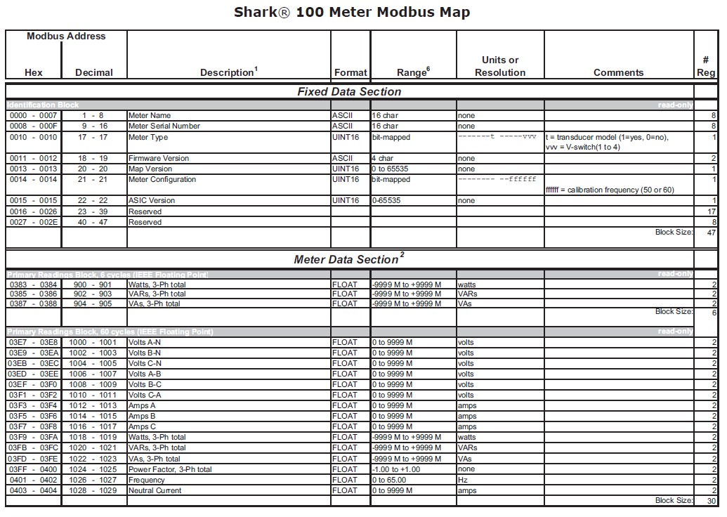
I'm having a problem with loan any floating point number correctly in the distance a 100 Power Meter shark.
I can read sucessifully a block of records containing the name of meter and the serial number as a 16-bit characters.
For example when I read records 1-16 on the map and flatten them into a string, I get a string of work completely returned.
When I try and holding registers A 1012-1013 (AMPS) I get really funny to read numbers when I converted to a float.
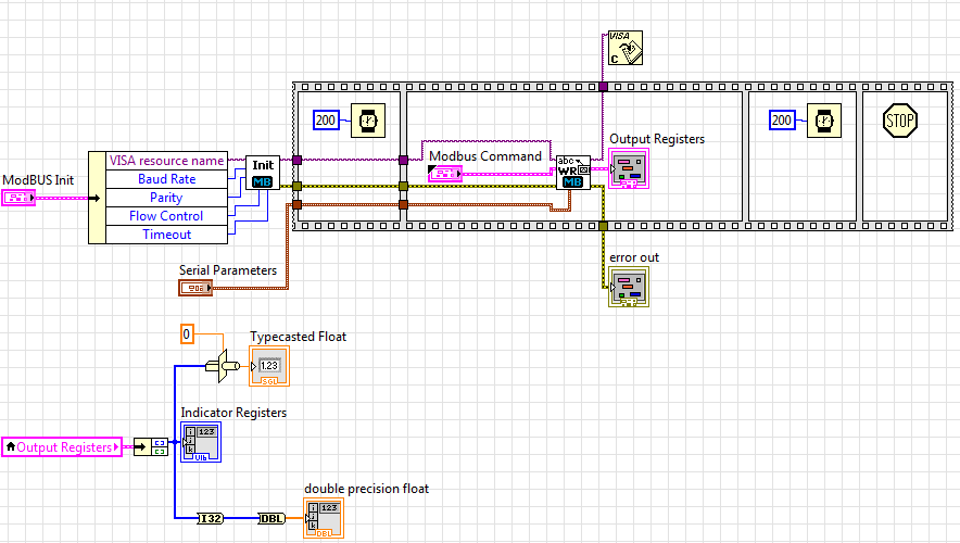
Here is my code so far
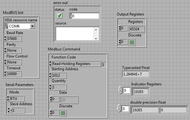
With my front panel settings:
Expected value, I'm looking to have returned: 11.11 amps
but
When I use an indicator to read registers: 19265, 0
Same value when I do a conversion
When I do a type cast to a float: 1.26484E + 7
I tried some different combinations such that read that a single register and join the numbers, both in order to big-endian and little-endian, still no luck.
Help, please!
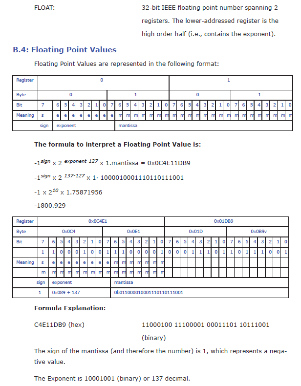
Here's the modbus float definition according to the owner's Manual:
Also, I saw that the Toolbox Modbus has sometimes behaving strangely of the off-by-one-register (so you need to actually ask a different address to get the desired data) and that some devices have a behavior even more strange out-of-one byte, while now you're out of half of a register, and you will need to ask for more records and then reorganize the bytes by taking a byte of the previous register or end.
-
MODBUS RTU read how to ignore the error
Hello
I have a problem, how to jump when the error of communication if I use the Modbus Library? I want this as smoothly without error on the chart.
Look at this video I save my problem:
https://drive.Google.com/file/d/0B_94Z4CwsTYeWEJpZUx2cVJ0a2c/edit?USP=sharing
I tried to mod on MB series Master query Read Input Register.vi using the box Structure in case of error. See this video and still did not work. any suggestion?
Thank you ~.
You put the error structure in the evil VI.
Put it in the main VI and table inside the no error case.
When you have it in the Subvi, the Subvi should always return something. If it returns is your data when it is not an error because you put the indicator in the case of error no.. Or if there is an error, it returns the default for the indicator data because you're not write all data on it.
-
Map of CRC-16 TR - M Communication, Modbus RTU
I'm writing the procedure for generation of CRC - 16 for Communication if card - M from TECO Electric and Machining Company. Here's the algorithm that they provide to generate the word of CRC - 16 (attached is my attempt to implement, I look forward to suggestions). Here are verbatim:
A. load a 16-bit register with FFFFH. Call it the CRC register.
B. Exclusive or the first 8-bit byte of the message with the low byte of the CRC 16-bit registers, put the result in the register of the CRC.
Register to shift of c. CRC one bit to the right (towards the LSB), zero filling the MSB. Extract and examine the LSB.
D. If the LSB is 0, repeat the procedure C (another change). If LSB is 1, exclusive or the CRC register with the value of the polynomial A001H.
E. Repeat C, D, until the eight shifts were made. Wile to do this, a full byte will have been treated.
F. repeat the procedure B-E to the byte following the message so that all the bytes of the message is processed.
G. when the CHILD is placed in the message, TI upper and lower bytes are to be swapped.
If anyone understands this, please feel free to tell me where I would not (see attachment).
See you soon!
jmcbee,
I have attached a vi that comes with the Modbus LV library. You should get the answer.
-
Hello Forums or
This is my first post on this forum and I've been using labview for about 8 months now
I have a problem about writing data in the modbus registers through a server of e/s defined as a slave modbus for my hardware 9074. Once I finished the project of construction and deployment of the variables and by following the instructions here , he reports no results but a row of zeros. I have the DSM nor opened and configuration modbus master to see whether the data is actually read or written on the respective sides that give the same line of zeros so. What I am actually trying to write is a single-precision floating data table. The registers are structured F40000-F46534 runs from 10 items or have them for range AF40001L1-AF46534L1 of the AF40001L10 point where it's an array of length 10. (Referenced beaches here)
I know 1 thing for you, the modbus connection works and is ready for data requests, I tested cela NI DSM and set manually the data for and received my master.
System and project specifications
Windows 7 operating system
LabVIEW edition development system complete 2011
No module Labview DSC, but I use the real time such referenced by one of the documents
This project is an application in real time with fpga mode (and not scan interface)
The master and the slave are the same network and subnet
Connection Modbus type: TCP
9074 compact slots rio 8
9234 module x 3
module 9221 x 1
9472 module x 1
Engine service Variable shared running on windows os and rtos system
Used this guide to learn more about the Protocol modbus, as I have searched all over the internet to learn more about modbus
I already have software Modbus IO Server installed on the crio thanks to max or 1.8 for NI RIO 4.0 version
file attachment (s)
Image of software specifications Crio
Image of data written in scheme-block rt variable
Short version of the problem: why is the e/s no variable writes in with the converted correctly data?
Okay, Yes, it's that I was the one proposed. Regarding the news of the error, if you look at the bottom of your image to DSM, you see a little commfail and an error code, but it seems that those are OK.
The only thing I can think is that DSM (or another function) is written for a range of values that includes 400004. I suggest you to put into service 4-going to a range of 3. 3 s are entered only (perspective control), then you can be sure that the master is not trampling on the data. Once you have checked that, look at DSM and any other code running to make sure q EU not accidentally write 0s to the same reg.
-
Exstance no of Modbus communication
I work with a rs232 for connection rs485 via a UNO2019 PC box. The RS-485 connection is going to be MODbus RTU, has about 4 slaves on the bus (MMI flowmeter, VFD, two temperature RTD). All theses devices are configured accordingin
9600 baud, odd parity, no flow control. the VISA resource would be COM3.
Now all of these components I worked with every day for numerious months. and VI implementation exists (almost) without error. I get an error code for the additional bytes to the port, but he spends the whole upward. I don't know if I'm not or write, but it has happened in every piece of software, I developed in labview (it does not check the boolean error so I guess that's not important).
Currently, when I try to read the registers of the MODbus slave, I get error:
-107380733 (that mean 100 different things that I have done my research properly, bad bytes to the port, do not use correct end characters in your message). But every time I have seen that error code discussed in question direct USB/RS232, not RS232 to RS485.
The attached string was
3-> MD series Master Query.vi
2-> MB series Master query Holding Register.vi
1-> address Test.vi
Thank you for any light you can contribute on my problem.
Problem has been resolved. It was a hardware problem as I thought. Apperently this code error will exist when your RS-232/485 is hard set via dipswitches do not send data.
-
writing multiple modbus registers
Hello
I am communicating to my labview program controller using modbus RTU and the controller has 16 bits in modbus registers.
To send the float as '1.23' values, I write two registers to store the hex value that number in comma floating 32 bits.
I use the modbus driver provided to this end by labview and use labview 8.2.1
I have the following doubts in this regard.
- The "Modbus master series query. VI"has the command Modbus that records an entry which I use to set the registry values in the controller unit modbus. To send the above, mentioned in floating-point registers 501 and 502 (contains the full value of the PID parameters), use the same vi, whose value should be registered first... is the high or low, to be written to 501 and 502.
- The function code to write to multiple records in the modbus driver is 16. But my document that is specific to the Controller explained in the section "writing to multiple records" with the code of function like 10. And I see that feature codes 'writing in the single register' as well as the driver for modbus producing the same type of message frame as discussed in the document. But I see no similarity in the function "write multiple registers" in the document and the modbus labview driver.
- "Even if I write records 501 and 502 one after another will use"write in the single register"function code when these registries implement floating-point single using 2 registers ' 16 - bit '. If this method is possible, then I will come and do it the same way I did it for the entry in the single register. While writing data in records one after the other with a gap between the two as small as 4 ms scriptures do good?
I suspect a confusion between 16 decimal and hexadecimal 10
Two successive registry entries are not equivalent to a double entry: during the period between the two scripts your controller will be loaded with a false parameter. It is perhaps not necessarily a source of problems. It depends on your application. Writing the MSB should first reduce the problem.
The order of Hi-Lo is dependent on the machine control. Some use the Big Endian, other Little Endian. But this choice should assign unique register values (U16) as well.
If it is not documented, you should read the records and see if the result is logical. If this is not the case, invert the byte order and verify that the problem is resolved. Good luck
Also, I assume that you know how to use the conversion feature to convert a single (32-bit float) 2 U16?
-
How to monitor the parameters using the Protocol Modbus in LV
Hello everyone
I have a problem with my LabVIEW project. I have to watch my monitor settings MI4100 Power using LV 8.5 and I don't really know how. I use the modbus RTU Protocol and I am able to communicate with the instrument, but I can't understand how to monitor records.
I have attached my comunication VI to see what I've done. Please help me if you can.
Thanks in advance, Sylvia
If you work with 32-bit numbers in need of two registers, then what you already do with numbers to reach work. Read 2 registers from 256, contact numbers, and you'll have nonexercising total power.
If you read only 1 register, then you will have a table of 1 item. Decimate this table and joining the numbers don't make any sense. You'd read comes directly from the registry.
What is the description of the error for 6002?
I don't see any reason why you wouldn't be able to read an address greater than 30.

Maybe you are looking for
-
Nobody knows how to solve this constant system restart? Anonymous UUID: 5EAFE90C-13B1-9D51-1130-4A1DA3D6CA79 Sunday, may 8, 11:51:59-2016 Panic report *. panic (cpu 0 0xffffff7f84efd50e appellant): "MCO GPU REGISTRY RESTORE FAILED: rdar://7254528, Ve
-
How to format the RAW file system in my pen-drive?
Dear friends, I have a 2 GB key USB "GENX". I used it for about six months without any problem. But now I have a serious problem that has changed its system of RAW files accidentally. I didn't really know what the reason for that! He didn't connect w
-
I can't nice administrator options on my tools
original title: turn on WINDOWS DEFENDER I can't nice administrator options fine internet options on my tools.
-
He seems to have picked up a virus in my Media Center audio files (Patsy Cline appears and my WMP has a clean mind - it can not control)... Is it possible to delete all of my Windows 7 Media Center, and then reinstall it without the virus? chromake
-
Windows 7 folders public icon missing
Hi all I see this problem has affected many people, but what fixed their problem does not work for me. I have Windows 7 Ultimate x 86, update, installed, but cannot access the public folder unless I go directly to the C:\Users\Public myself. I showe