Question of Gibbs phenomenon in square wave of labview builtin function generator
I have a server and a client, I send commands on my client's server to generate different signals. but the display of my square wave and a waveform sawtooth in the client a Spades and lots of harmonics to it. When compared with the display of the same waveform in my server, the square wave and sawtooth wave appears. Photo will show a comparison of the two.
Please help, I did some research and I think it could be the gibbs phenomenon happening and I'm not sure how to resolve this.
Tags: NI Software
Similar Questions
-
Square wave generation phase offset problems using PXI6602
Hello
I'm generating 2 signals using an incremental encoder AB using a PXI6602 to simunlating.
Signals must be offset square wave, 34,133 Khz, by 90 degrees, which I'll put dividing (1/frequency) into 4 and put the result in the knot of late initial .vi DAQmx create channel (frequency impulse Co generation).
Resulting signals phase difference however does not consistantly measures 90 degrees. 1 in 5 rounds of the vi has at least a matter of resulting in a test phase angle has failed.
Can someone suggest a stable solution for this.
Thank you
David
John_P1,
After posting the previous comment, I went back to play some more with him, and he now runs and returns a positive result every time.
The change that has had the desired effect was for the type of trigger that I had selected (Advance Digital Edge). Change this to start digital dashboard whose value fall of dash, the error disappeared.
Feel free to always criticize the vi and suggest / modify to improve stability / efficiency.
All feedback is voluntarily accepted

Thank you
David.
-
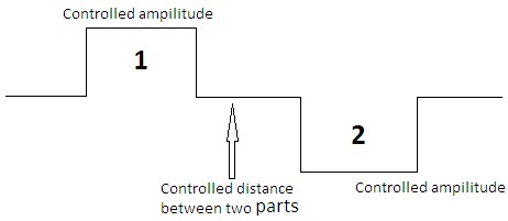
How can I design square wave which has a positive and negative values equal to the other and separated from each other by controlled time or distance, as indicated in the figure below. and enter this signal in a data acquisition.
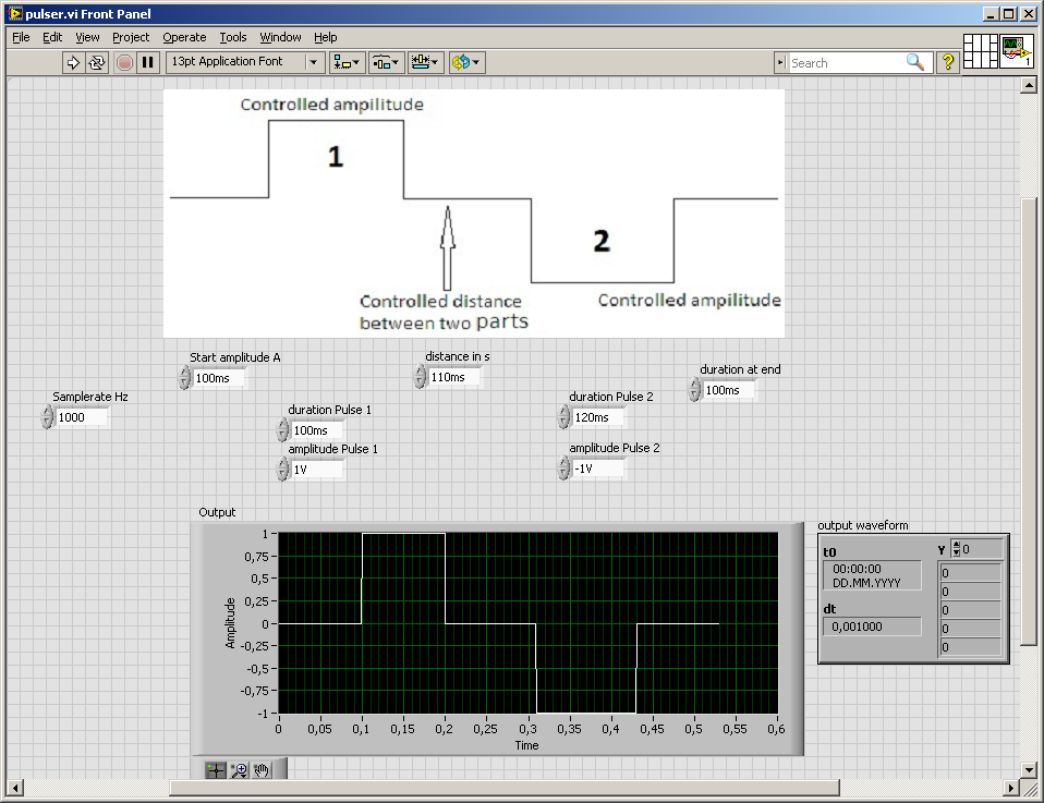
At the time wherever you go for the beautiful diadram, you could have done the vi

Your DAQ would like a waveform (table of values and dt ak 1/sampling rate)
If you set the sampling rate you know the length of the array, create a matrix of zeros and set the values of the two amplitudes...
Because I don't want to connect other duties
here are some photosAnd it
does have a few drawbacksleaves to be desired in my solution, just think... rounding errors and what might happen if the tables are becoming more... -
Best way to generate signals of activation (square wave) with my 9401 on my 9022?
Hi, I tried seriously over the past two days to find the best way to do it. I am trying to generate a very precise square wave, controlling the duty cycle and frequency, with the OID on the 9401 in testbed cRIO 9022.
I have a VI that is theoretically able to do this, but whenever I try to go above 5 Hz or more, duty cycle and frequency becomes inaccurate (I have watch on an oscilloscope), various a lot too for my needs. I have a feeling that this is caused by my addiction on the calendar software controlled, with errors at the time (of the ms order) accumulate as they get processed and the signal is sent. I have attached a piece of code that illustrates the basic idea of what my VI have in them.
I have avoided the square wave generators integrated because I could never work to satisfaction, but I can work with them so that will solve my problems. Selection structures and cases prevent the user to exaggerate their inputs. Unwaited so the loop was just to test.
I'm running the 9022 as target in real time, but also tried to run in the FPGA and I was able to produce much more accurate signals using FPGA VI square wave, displaying a Boolean variable, but I couldn't see the best way to get double precision variables to work with everything (and I want more precision than variables FXP enabled clock 40 MHz).
I feel there is just a mistake in my approach here. I've seen other discussions where people throw around using meters to edge of the test bench to produce a square wave, and I see the example screws as Gen dig pulse - continuous Train, I'm not sure if initially these screws DAQmx for my situation (eg. How to identify my counters, because they are clearly not Dev1/ctr0 by default in these examples)
Thank you
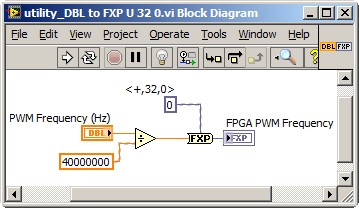
Dealing with the representation of Point fixed and all is a reality for LabVIEW FPGA<= 2011="" programmers.="" you="" might="" build="" a="" small="" sub="" vi,="" such="" as="" the="" one="" attached,="" to="" encapsulate="" the="" frequency="" calculation,="" thereby="" abstracting="" the="" conversion="" formula="" and="" fixed="" point="" data="" type.="" you="" can="" adjust="" the="" properties="" of="" the="" floating="" point="" input="" control="" to="" accept="" only="" valid="">
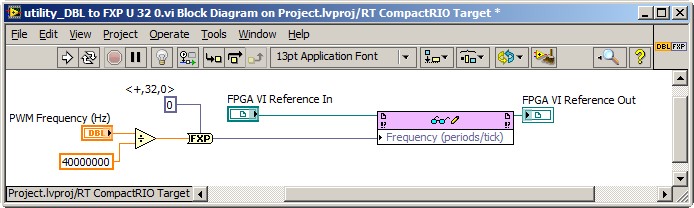
This implies the series VI void on the host of the RT, and not on the FPGA target. So, you also need nodes in the Palette of the FPGA Interface to send PWM fixed Point RT frequency to the FPGA. The complete solution of frequency may resemble the following. It is common for FPGA programmers to build a collection of thesesub screw, that make up the API for hardware.
Note that 40 MHz is hard-coded. For increased flexibility, consider making the FPGA clock rate an entry to the Subvi with a default value of 40 MHz.
-Steve
-
How can I get a continuous square wave to the duty cycle of 50% on one of the analog lines?
Hello, I had recently just buy an analog card to our system, and I'm still very new to labview. I have the PXI-6723, and I need to produce a wave square of 0 to 5 volts continuously. I used the square wave generator and used a writing funtion to one of the ports. This produces a momentary wave and that's it. I tried to put some time a loop around the square and watched as wave function. It produces constantly plots, but the write function always has the same thing. If I am the writing inside the loop function I get errors. Any help would be greatly appreciated. Thank you, Fred
Another function to generate the square wave, to change the generation of waveform buffer (the Subvi used) and to connect a control at the entrance to offset from the base generator functions. or simply use the add function on the output waveform.
-
market factor two AO signals with a square wave
Hello
I use two devices with sending two signals (sine wave) AO out simultaneously in my code. I need to have to cycle my signals. in other words, I want to start or OFF the devices at all times. To do this, I use a generator with duty cycle of 50% square wave. The devices must be running when the square wave has positive values and should be OFF when it is negative.
The code almost made it, but it doesn't seem to be as fast it's supposed to, based on the frequency of the square wave. I was wondering if someone can help me with this problem. In addition, I'm not sure if this is the best method to do this, please leave me know if there is a better way. I've also attached the VI.
Thank you
Pooya
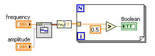
I thought about it. Instead of the command at the AO signals with square wave and the structure of the case, I just made a square wave from 0 to 1 and multiplied the wave sqaure to the AO (sine wave) signals. In this way, when the amplitude of the square wave is 1, it sends the sine waves and when it is 0 it sends 0.
Please note that all signals (sine and square) should have the same info of sampling.
-
How to read the digital square wave pulses
Hello
I recently bought a blue-white meter. I have successfully read the digital square wave from the sensor. However, I face a problem to calculate the flow rate and the total volume of liquid. Can someone help me with this?
Technical data of the flowmeter can be access to the http://www.blue-white.com/Products/ElectronicFlow/MicroFlo/80000-406_microflo.pdf. And the calculation can be found on page 9. I use NI9401.
Thank you
-
Generate a continuous output of square wave with E Series DAQ cards
Hello
I use a card DAQ-AT-MIO-16XE-50 and labview 6.1 to generate the frequency divider. The first thing I want to do is to enter a continuous digital signal into the program so I can divide it. The attachment is the program I use. It's pretty simple, just read the output signal and put them all in a while loop to get a continuous pulse. But when I want to observe the waveform on the oscilloscope, I got some square waves unregular.
I'm a freshmen in labview. It will be appreciated for all her help!
Hello
If you are just getting started with digital i/o with traditional DAQ, I'd take a peek at some examples to see how to structure your code for both input and output. There is one here (http://zone.ni.com/devzone/cda/epd/p/id/1113) which should give some features similar to what you are looking for, but if you want more examples, you can navigate to the examples as a result of the article here (http://digital.ni.com/public.nsf/allkb/46D0C7360A10D25F862571B5007B4411), as long as you have installed them with traditional DAQ.
-
Hi all
I want to check if my digital square wave turns on or off. If someone has an idea, please help me
I created a mask, so that if my signal leave the mask. I have an Error Message. "It's job but every time I should change the values of the function Culsters ' specification limit" if I change the Signal
You will find in the attachment the block diagram.
Thanks in advance for your answers
Best regards
How are you brightness measure? A digital signal is enabled or disabled.
Duty cycle that you can measure quite simply. There is a VI called Pulse Measurements.vi who will do it for you.
-
FPGA square wave generator diverts loop calendar
Description of the problem:
I have a simple while loop with a structure of matter inside. In one case, I have the
Generator FPGA Sinewave sending the data of output to AO0, otherwise, I have
the square wave FPGA sending output to AO0 generator. The sine and square
waves are set to run at 10 kHzI also have a shift register that changes the State of DIO0 each loop through.
In this way, I can look DIO0 on my scope and say how fast the loop runs.When I choose the sine wave generator, the output on AO0 is what I expect. That
is I have a sinusoidal signal at 10 kHz and the loop speed is approximately 1 US. Everything is good.Then I move to the square wave. I get a signal square 10 kHz, which is good. But
My loop speed was slowed down to 50 US (it follows the square wave
exactly) is: once the loop defines the FS square wave and the
the next time through the loop, it defines the square wave to-FS.My problem is that when I generate a square wave, I expect the speed of loop
to stay fast he does it for the sine wave. You can see what my loop speed
slows to 50 (a square wave of 10 kHz) and then all my calculations that must
go in parallel with the square wave will also be slowed.Please help me with my understanding of the use of the square wave FPGA sub - VI
Thank you
RichSoftware of NEITHER: LabVIEW FPGA Module version 2013 SP1
OR hardware: USB-7855R R Series deviceIf you dig into the express VI, it will loop an SSTL until there is a change in value. The sine wave has no need to do so because the value changes constantly.
If you can, I recommend doing your loop a SSTL and configure the express screw accordingly. This will work as long as the rest of your code in the loop can be run in a single clock cycle.
-
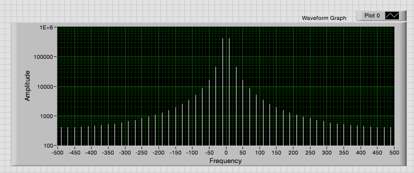
transformed of Fourier of the sine and square wave return is not the frequency of the wave.
Hi all
I did a few programs to determine the Fourier Transforms of the sine waves and square waves. I understand that square wave harmonics when FTed but the Harmons of the square wave is not out at the right frequency and neither is the sine wave. Any help would be appreciated. I have attached my programs, so you can take a look.
Thank you very much
M
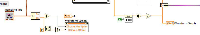
The axis of your frequency VI is missing.
Given that the data are sampled in a uniform manner, you can use a regualr rather than the graph XY Chart. Then you need not create a table of the x-axis. A property node to set the frequency axis scale multiplier and offset.
Lynn
-
With the help of modulated signal pulse width (square wave) to control when a signal is enabled or disable
Hello all
I am using a modulated signal to labview created pulse width (square wave) to control when a signal is activated or not.
Here is my logic and a concrete example:
(1) the wave source signal is continuous
(2) use a PWM (square wave) created in labview to control when the signal is enabled or disabled
(3) if the PWM (amplitude) signal is superior to 0 play signal PWM is not greater than 0 do not play signal.I use actually this to the sequence step / pulse several distinct magnetic coils using my audio card (which has several channels of audio output), I have a signal in labview played constantly. As to compare it to the PWM (square wave) which controls whether or not the signal is played on each separate channel. That way I can control which coil is on and offshore and in what order they are activated.
I couldn't find an edge detection for a square wave created in labview, so I tried the limits, but it doesn't seem to work unless I change the phase manually and it only goes 1-1. I'm just trying to compare the PWM (edges of the square wave) already created by labview / play a signal if the pulse is greater than 0 and it shuts off the signal, if she is less than 0.
Should I do this another way
TIA
A waveform contains an array of values. You must check every value and respond accordingly:
-
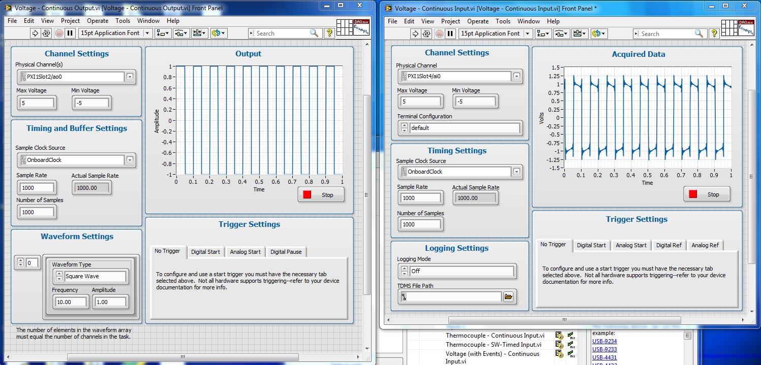
unexpected noise of the square wave
Hi, I just run a simple test: connect PXI4461 with the PXI-4498 via a BNC cable. Using the LabVIEW gave examples: voltage output.vi for input.vi PXI4461 and continuous tension for PXI4498. I want PXI4461 to produce a square wave, however, on the side of detection, I found that there are unacceptable summits on the rising and falling edge. There are also some signals oscillating in the stable phase. I wonder how that happens and is there any method to solve that?
Thank you
KevinKevin,
In the NI449x standard:
Part of what you see is the effect of AC coupling. Cut-3 dB frequency is 0.5 Hz. Indeed the unit sees the horizontal sections of the wave of entry as a DC signal and the coupling capacitor begins to charge. This explains the slopes of the signal acquired during the constant part of the entry.
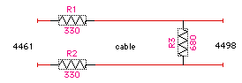
The ringtone and the go-around are due to the impedances are mismatched. The output impedance of the 4461 is 22 ohms while the the 4498 input impedance is 10 Mohms. 35 PF. The signals do not cause reflections on the transmission line (the BNC cable).
The ringtone can be eliminated by having matched to the source and load impedances. However, the acceptable minimum load of the 4461 is 600 ohms which is much higher than the output impedance 4498.
A network like this will match impedances at both ends of the cable, but will reduce the signal by about 1/2. Your actual load can not find more acceptable source impedance.
Because the 4498 does not have a DC coupling option, there's really nothing you can do the signals on a slope.
Lynn
-
FPGA (PXI-7852R) Square Wave DIO
I need to improve the noise to the DIO square pulse pulse width. With my current code (attached .png) I see 25 ~ ns jitter on the front coming down from the impulse (I have the trigger on the rising) with my oscilliscope. This Jig is present even with only a single output square wave (i.e., I delete the other square wave generators).
Any ideas how to improve the fidelity of pulse width?
Thanks in advance!
25 ns is the period of your clock to 40 MHz, the jitter is unavoidable at this clock frequency. The DDS square wave algorithm produces a very precise frequency over time, but cannot control the speed at which it is called to update.
If you set the clock of the loop to a greater frequency of derived clock, you shoot the Jig by the same factor. Right-click on a 40 MHz clock embedded in the project with the FPGA target and choose new clock derived from FPGA. You may need to experiment a bit to see how high you can set the clock frequency without introducing sync in compiling violations; new targets will allow higher clock rates generally. Set up your single cycle timed loop to use the derived clock and don't forget to update your average square configuration with the new clock frequency.
-
minimum frequency of the square wave generator?
I am trying to generate waves with a frequency lower than one, but it doesn't seem to be possible for some reason any. If I put it to 0.5 (for example), I just get a flat line. Tried to turn around the details of sampling (frequency 1 and Fs to 500) but still no go. Is it possible to generate frequencies below 1? Thanks in advance
Assuming you are using the square wave function, simply set the number of samples to twice the sampling frequency of a.5 Hz signal. The default value of 1000 samples/s and 1000 samples gives you of course, 1 second of a data value. Pour.5 Hz, you must display 2 seconds to see the whole pulses (1/.5).
Maybe you are looking for
-
How do I enable the allow_url_fopen option
I use a word press plugin on my site which requires the directive allow_url_fopen is enabled. It is currently disabled. You you please activate it on my server so that it comes into force in all of my sites.
-
Pavilion 15-ak006nc (ENERGY *): keys to Action and touchpad problem
Hello I just bought new HP Pavilion Gaming Notebook - 15-ak006nc (ENERGY STAR) with W10 home x 64. In the beginning, I have problem with action keys. They are as default, so when I press F5 to refresh something, it turns on just the keyboard lighting
-
A company that claims to represent Microsoft were constantly phoning on internet security. He site is "msonlinetechsupport.com". Are these people really call on behalf of Microsoft as they claim?
-
keep getting dial ras in windows it can not conect wireless how to fix
Keep ras dial in windows this on my netbook can not conect wireless how to fix or there at - there no virus program to do a scan of all the programs I checked is not compatible win this
-
Server 2008 with customer connection XP errors
After 6-12 hours of connection, I get the message "The system detected a possible attempt to compromise security" on sconnected XP workstation to a Server 2008. Player connections stop working until the workstation is disconnected and turn it back on