Re: RLC
Hi friends,
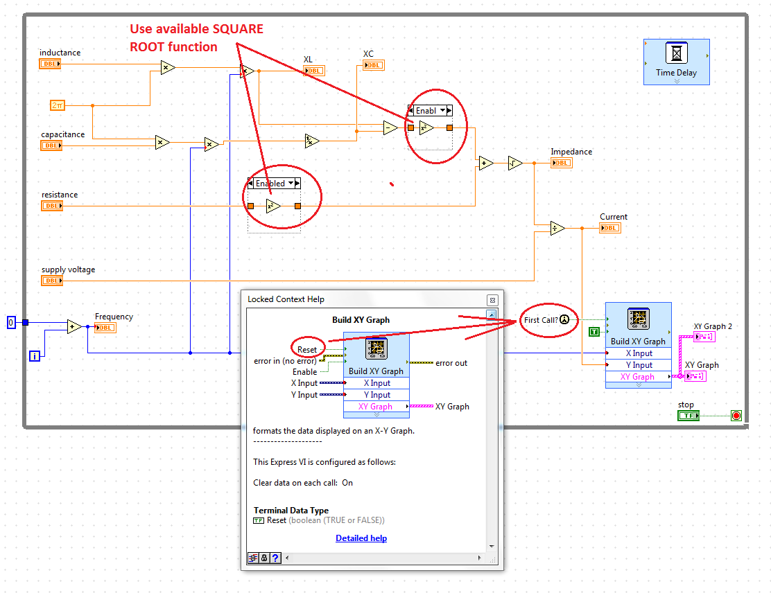
I designed the RLC circuit using labview. Everything works fine, but still I couldn't see any waveform in the graph XY.
m kindly helps solve this problem.
For your reference, I have attached my RLC vi. Please take a look and let me you if there is no correction
You forget to do 'RESET' false (which is by default TRUE).
There is also a direct feature available for 'Place'... by mistake I mentioned as 'SQUARE ROOT function use'... just ignore it...
Also find home edition VI.
Tags: NI Software
Similar Questions
-
RLC, AC single frequency analysis results do not match hands calculated results.
On a single RLC monofrequency simulation analysis AC, the amplitudes resulting are off by a factor of 10. Phase angle values are all correct and correspond to the calculated values. On another example developed in a text book, same results. What I am doing wrong? In addition, how you change the ca of RMS to peak source or vice versa? Thank you.
-
Analysis of RLC circuit in parallel with C AC
Hi all
AC circuit analysis attached does not match the analytical solution of the circuit.
Any suggestion?. Could it be related to the value of the capacitors?.
Thank you for your help.
By default, Multisim inserts 1e12ohm (RSHUNT) of each node on the ground resistance. Due to the very small caps in your circuit, impedance to node 3 becomes very similar to this value and take the results. Setting RSHUNT, go to AC analysis-analysis-> options > customize-> Global tab uncheck RSHUNT remove or increase its value.
-
Apple tv (2nd generation) hbo now
I have a 2nd generation apple tv (6.2.1) and I'm having problems to display TV on HBONOW programs.
I can see movies without problem, but try to view TV shows causes the HBONOW app down. (sometimes, he appears a loop; e.g. spinning wheel)
I have contacted HBONOW support and went through all their troubleshooting procedures. I was informed by them that the problem is with the apple tv (point 6.2.1) software.
My questions are: 1. is what support HBONOW said that the real problem?
2 is Apple aware and working on this issue?
3 is it possible for a regression away (point 6.2.1);
4 is that what someone else with similar experience?
FYI, I have no display my MBP 2010 performer 10.11.6 HBONOW problems; but it doesn't support airtime.
Ideas or suggestions appreciated.
Thank you
RLC
HBO now for OS X is not an app, it is based on a web page
HBO now for mountain BIKE depends on the application, developed by or for HBO under their influence.
Apple tv OS 6.2.1 was the last update from Apple for ATV 2 and Apple supports more unit shortly after.
so:
(1) it is perhaps true, HBO is decent with troubleshooting.
(2) Apple has stopped support for this purpose the issue is and will always be with HBO. Even if Apple suddenly starts to support ATV 2 its still a HBO problem to the extent that Apple is concerned and sketched in their license of USE of the device. HBO is the party who needs to fix their application in accordance with the framework of the 6.2.1 operating system compatibility
(3) to a system restore restore your Apple TV to its factory - Apple Support settingsto reset the unit with its current operating system there is no way I know personally to downgrade Apple TV.
(4) I've had personally not a problem with HBO now, but I ATV3
-
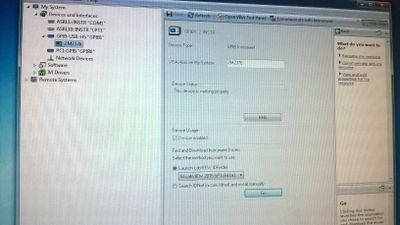
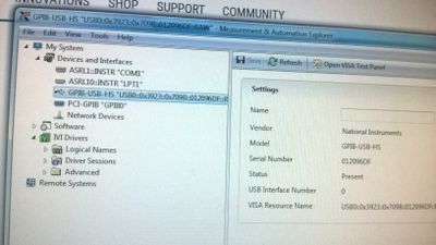
GPIB-USB-HS shows no MAX after that I used the wizard NI VISA DRIVER
I accessed GPIB USB HS in the MAX software. As I was not able to communicate NF RLC remotely, so I tried Wizard DRIVER VISA OR according to tutorial Assistant pilot NI VISA , however, thnings went wrong and I am not able to see same GPIB to the MAX software now. What should I do now?
The first picture below shows the GPIB USB HS as shown in the software MAX and the other image shows no GPIB USB HS.
Yet once I installed driver USB GPIB link below:
http://www.NI.com/download/NI-488.2-15.0/5427/en/
Its working fine now.
Thank you.
-
Hello
I am trying to develop a system to monitor the components on the cards of PCB in the oven, it s essentially has a failure analysis of components such as C, resistors and capacitors.
Here are some of my test system
The test system must monitor the components on the PCB 1 year.
I want to measure the resistances and abilities using a RLC to identify the problem. Failure of the resistance is identified with an open circuit and a failure of the capacitor is identified with a circuit short circuit/open. I have a 420 capacitances to measure and I would like to automate the measurement using multiplexers of NOR.
I got to watch the first ability (C1) 3 minutes (which would be linked to the first input of the multiplexer), followed by second 3 minutes and so on. Once all 420 capacities are monitored, the loop must start from Capacitance C1. I would like to know how to program the switches of the NOR. Could someone please suggest me how to proceed with this. ? Is good enough to automate Labview switches or should I go ahead with the switch management software? Can you please explain in detail because am a beginner in Labview? Forward to your response. Thanks in advance
Hello switcher.
Yes, LabVIEW is an ideal programming environment!
 .
.I suppose you have no switch OR equipment at the present time.
Measurement of the capacitance range are you watching?
What voltage are the plugs at? Looks like it's just a test section, but I guess the capacitors to be held at a constant DC bias? (Otherwise, the test data that you collect is capacitance of the real world).
Without any specific input except the number of capacitors, I recommend 5 multiplexers of PXI-2575 x configured as a 2 son 98 x 1 mux. You can use the PXI-2575 x modules only 3 in mode 1 wire 196 x 1 if your DUJT capacity is sufficient to overcome the parasitic capacitance total of 420 caps (all the negative wires would be linked to the negative contribution of the IGS), but I recommend the approach 2-wire, because it isolates each CAP in a differential measurement.
The PXI-4072 has a function of measure of ability.
With respect to the software, I recommend using NOR-DAQmx switch API, but you can also use the OR-Switch and NI Switch Executive API as well. However, I think that NI Switch Executive is excessive for this application, and it will take a unique session for each switch OR Switch module (OR-Switch is consistent IVI and IVI has no concept of linking several modules).
.. ask away if you have any questions. I'm not "wait I answered them: all in this first response."
-
Why my instrument sends the response to the last command sent?
Hi so I'll try to schedule this RLC SR720 via a USB/GPIB interface. I can communicate with the machine and it does almost what I want, but this oddity and I suspect I'm missing something basic. The manual can be found here.
It meets the common as GPIB commands * IDN? (specify the instrument) and * IFC (clear device), so I'll use those. I want to use myself is xall?, which requires just the currently measured data.
The problem is that it seems that the machine always "blame" a late order. By example, if I ask * IDN? with NI MAX, it returns what it should. However, if I can ask xall?, it always returns the same thing as * IDN?, until I do xall? Once again, then it returns to what it should:
-> * IDN?

<->

-> xall?

<->

-> xall?

<->
Even if you go the other way:
-> xall?

<->

-> * IDN?

<->

-> * IDN?

<->
As you can see, it is "late" a single command.
The manual says:
Similarly, the SR715/720 has a 256 character
output buffer to store the output to the host
the computer is ready to receive. If the output buffer
It fills is cancelled and an error reported. The
GPIB output buffer can be cleared using the
Clear device universal order.So I thought I would try the clear control device (* IFC) before entering a new order, but it doesn't seem to work:
-> * IDN?

<->

-> * IFC

-> xall?

<->

-> xall?

<->
Does anyone have an idea what might happen? The manual says to use the line as the terminating character, so I'm, but it seems not to matter.
You have everything waiting between your writing and reading? Have you tried to do a reading before your order seding?
-
Missing components in my file Ultiboard if I transfer my file Multisim
Hello!
I am after this Introduction:
http://www.NI.com/white-paper/10710/en/?CID=Direct_Marketing---em80795&espuid=CNATL000018702741
On the point
5. the part D: transfer to PCB Layout
"" (8) select transfer "transfer to Ultiboard ' transfer to Ultiboard 13.0 and save the netlist file. Ultiboard opens automatically
This pop window ups:
Components with no package will not be exported.
See the results tab in the spreadsheet for a list of these components.Continue with the transfer?
I press ok, and my thread Ultiboard opens.
My resistance do not appear in the file ultiboard.
Any tips?
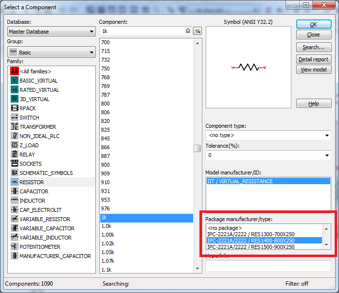
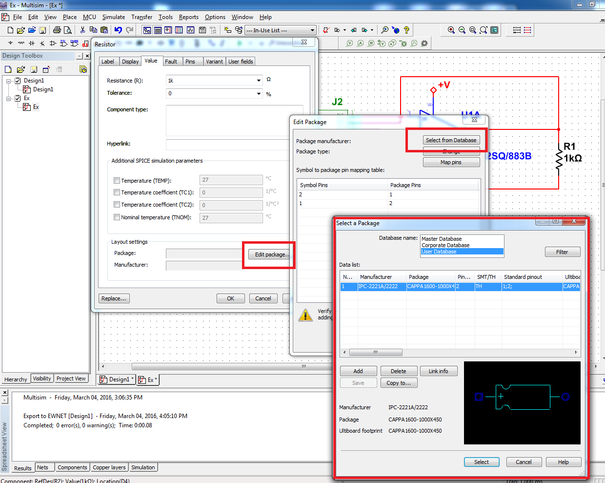
By default, when you place the RLN base, it has no assigned package. The package contains to Ultiboard layout information. Is this the message you saw said you, that the list of components in the spreadsheet was not exported to Ultiboard because they had no information about the package.
If you want to be able to transfer your RLC to Ultiboard components, you can choose a package when placing it down on the diagram:
Or you can add a package to a component that you have already placed. Double-click the component to open its properties and click on the tab 'value '. From there, you can edit the component package and select one in the master's degree, business, or the user database:
Let me know if this helps.
See you soon!
The f
National Instruments
-
Nice day. I'm a newbee in the true sense of the word. I have read the quick guide on this site, but I'm not sure I'm in the right place for this very basic question. I'm trying to establish communications with an Agilent 4263 B RLC and LabVIEW 2014. I use a GPIB PROLOGIX USB controller and supposed to be someone already had this computer and this LCR Meter speaking, earlier. I have training manuals LabVIEW Core 1 of someone who has been through the class. Unfortunately, they are not available to help me. If someone could point me in the right direction would be great. Thank you
Name of the resource that you use? A you select in the menu drop-down?
I have no idea on the combination of the instrument and prologix. In theory, you should be able to communicate with it, but I have never used the prologix and I hope, will never try.
-
List of Agilent E4980A E420 sweeping request not completed
Hello
I am Agilent E4980A RLC control with labview 8.6 GPIB to measure the ability for several frequencies. I was able to run the frequncies LIST SWEEPING up to 65 points with no problems. Buy if I want to measure more frequency points (say 70 points) then I got the error of request not completed-420. My LCR Meter works fine if I trigger it manually with 201 points of measurement (maxinum limit points of the LCR meter). I used the driver NI E4980a. Does anyone have the same problem? Thank you.
Soon
I have change the calendar from 10 seconds to 30 seconds and it works now. Thanks to you all. I really appreciated your assistance.
-
Generic footprint resistance disappeared.
Hi all
I use Multisim 10.
When I place a resistance, the generic print disappeared from the options in the print (1). When I place a resistance to virtual with no footprint and select a print manually via a right click > properties > change the footprint (2), I can choose the footprint (3) 'Generic - RES0.25' I was originally after. I've attached a picture to illustrate the options I have. Anyone know how to recover these generic prints in the options of the original print (1)?
Thank you very much
Dan
In version 10 or later, RLC components are treated a little differently from the regular components. To add a mark to the list in the browser to Select a component , you must add a new definition to a resistance.
- Click on Tools > database > database manager
- Select the Components of RLC
- Click on the Add button
- Define the following information
- Family name: RESISTANCE
- Value: 1 k (can be any value here)
- Footprint manufacturer/Type: generic/RES0.25 (or the mark you want to add)
- Click OK, close
-
How to make the control to agilent 4980 after completing a measure of labview?
I've been using the driver given by national instruments for the measurement of reading on the agilent 4980. The measurements are made very well, but after the measurement is done, I can control is no longer the RLC physical. Can what changes I make to the program to return control to the RLC physical?
I have no instrument of agilent, so I have no idea. You need find and go through the communication for the 4980 manual and see if there is a command. You should be able to get on the site of manufacturers if you are lucky.
Worst case it may be a reset command and then you need to stop communicating with her, otherwise she would probably just go back in a State remotely.
-
XY graph in time real conspiracy
Hello
I'm creating a program of measurement of C-V-T using HP4284A RLC and Lakeshore 330 temperature via gpib controller. I'm of the temperature and voltage scanning. I need to have a simultaneous ground CV and I use an XY graph to display. My problem is when the loop set in the iteration next steps back without erasing the graph for the scan again. Can someone please help me find how to clear the grap of old values each scan
Thank you
Jean-Marie
Hi odimuthu,
My problem is when the loop set in the iteration next steps back without erasing the graph for the scan again.
Usually, you would create another plot in the same graph for the next scan!
When you really want to plot the data in the current sweep you must delete the data stored in the passage records (aka feedback nodes) when you start a new scan!
-
Using the producer/consumer with GPIB/VISA model
Hi all
So I have a .VI I learned to communicate with my camera, I joined. I tried strip down as much as possible, just to understand the concept. It basically just takes a resource VISA name, use this open VISA, then uses the same resource VISA to write a command that reads the data from my machine (xall?) and then bed in 500 bytes and which prints. If it works, and it's good.
I try to use producer/consumer model for doing essentially exactly what this guy. I have a RLC, I want to press a button that starts my measure, I want him to taste several times per second, save the data in a text file or .csv and then stop when I press the stop button. Thus, he will be given indefinitely potentially.
I would like to have the data in a format something like:
Time C R
0 5.0 4.3
... etc.
I read the link of model p/c above, but my LabView knowledge is still low. Currently, my plan is to take the part of read/write of my attached VI, which are a sub - VI and then put that in the pink box in the VI for the producer/consumer above page that is labeled "produce data to be placed in the queue":
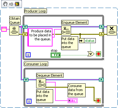
What prevents me to do this, it's that I can't get the piece of read/write to work properly as a standalone Subvi.
What is the right way to go about this?
Thank you!
I put if you actually found data of your instrument. Your instrument is not made to take new measures or just send you the last reading, she did.
Insofar as the file IO, I recommend that you learn to use the palette for the file IO functions. You need to create your file before your loop, write in a text file inside and then close after the loop. I don't do the thing the comment on the express VI entry will do what you want.
-
Hello
I want to do a few steps under dc voltage power MOSFETs. I want to make all measurements automatically. I want to be able to change the connections of mosfets using relays which are controlled by the remote PC. This means.
First I'll connect CC mosfet (it has port HPIB) by connecting it via a remote PC. And DC stress on mosfet.
Second, change the connection of the mosfet to RLC and make and registered these measures on PC via HPIB.
MOSFET, LCR Meter POWER DC supply connections will be done by the PC remotely controlled switching relay.
Anyone who can show me a way?
Thank you.
Maybe you are looking for
-
Neches engineers-Wifi for iPhone6 security setting
HelloI'm working in Neches engineers Thomas. I want to know about Wifi security configuration for iPhone6. Thank youThomas HansonNeches engineers
-
Satellite P850 - 31L loses connectivity Wi - Fi every 2-5 minutes
I fall every 2-5 minutes.What happened since I bought the machine regardless of network or location. I can usually correct with "Troubleshooting internet connection" microsoft reset of the card, but that takes a few minutes also. Sometimes I have to
-
Satellite L300-PSLB8A-01F004 - need help downgrading from Vista to XP
OK, I downloaded all the drivers for my L300-01F004 PSLB8A, now I have all to stick them on a DVD, remove the existing HARD drive, then installing XP on a new HARD drive?I know there is a hidden partition on the existing HARD drive, how can I create
-
Admin for computer laptop HP 2000 or power on password recovery
I try to put on my laptop and see a black screen with a blue box asking for password admin password or power. The passwords that I entered will not work. In any case substitute?
-
Code 646 Windows has encountered an unknown error.
I am running Windows 7 and have several updates that are not installed. Most were in Office 2007 that I unchecked as I do not use Office 2007 (he hated!). Are the 2 other updates to Office 2003. I've disabled my virus scanning program and tried th