Ridge table waveform detector
Hi all
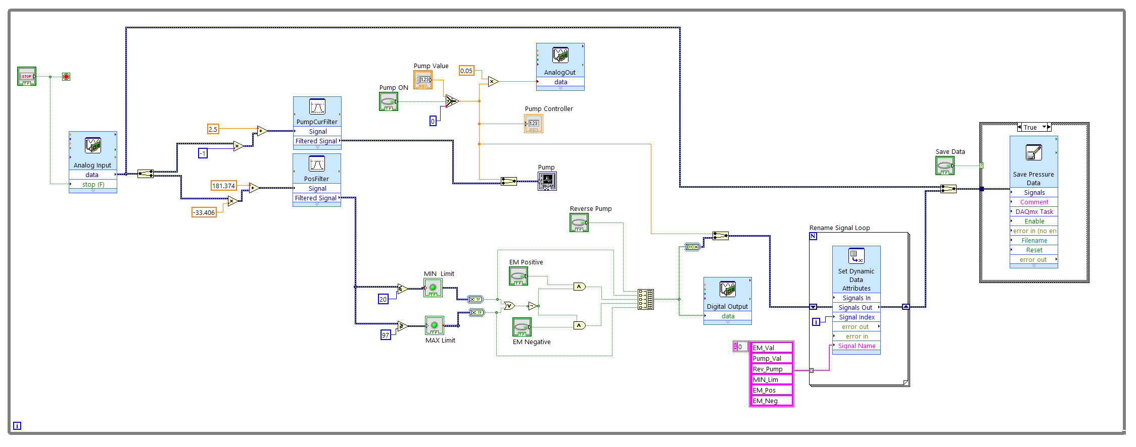
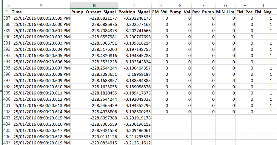
I have problems trying to work with the Ridge detector tool... I have a file which contains 17 columns, that the first's time and the rest are data... I split and now Im trying to find the vertices of the first wave... I'm looking around and I find that it is only something bound on how the Ridge detector to receive data. IM now trying to convert the files again in a table, but only inside labview and I think that will solve this problem... but I can't.
Please if someone could help me I will be really great
In the attachments, you can find the .vi file and the excel file to run the program...
Thank you...
In Excel, I save the .csv file in .txt file and then do something like shown in the attached VI by reading the file using "reading of the File.vi worksheet. This way, you have full access to real values, including the table of time within the LabVIEW program... Don
Tags: NI Software
Similar Questions
-
How to record entries of UI with the data measured in a TDM file?
Hello
I built a user interface to monitor and control a pump test bench, I use the USB-6212 in a Windows PC with the new SW and readers.
Now I try to collect all the measured data and control values in the UI, permanently at 1 kHz and write it in a single file of CT.
The problem is that only the measured signals get connected, but only a few values at the beginning of the file are saved in the user interface; then all empty.
I have all tried, producing waveforms, synchronize them with measured data for the same stamps, aling & resample and blocks of collector of the Toolbox Signal Express, but there are still some missing data in the user interface.
In my original configuration, indicated in the post, I set up the block of analog to read continuously at 1 kHz with 100 samples, while output and analog digital on-demand writing. I have included the file complete, just in case some block causes disruption.
Your express DAQ screws will probably be reading/writing of multiple samples for each run, then wire you a single value for your set points. The use of the data type of dynamic signals hides this information from you (that's why nobody is using them once they become more familiar with LabVIEW).
You need to take only the last value of dynamic data, or touch your set points so they are the same size as your dynamic data. If you write 100 samples at a time, then you will have your set points only once by 100 values. You must create a table/waveform of 100 points with the same value.
-
Data related to communications received conspire RS-232
Hi all
I am trying to receive data using the RS-232 serial communication and plot the data in real time. I have a 24-bit data at the transmitting end, so I use "Join numbers" block in the labview to join the three 8-bit data (the final result is the 32-bit data after joining the numbers with 8-bit zero value data). After data entry, it is sent to the waveform table. The received data should be Wescott on 8 different waveform cards, while the first 24 bits data are Wescott on the first chart of the wave, the second 24-bit data are Wescott on the second table of wavform... This is the reason why the 'String subset' block is used.
The next two links show the block diagram:
As you can see I am highlighting the process execution. If in the first link I showed some data arrives to the waveform charts. But in the second link, you can see that each table waveform except two are conspiring the value zero. My question is why what is happening?
I am aware that there is an error in the communication, but it should not interfere with the layout of data.
Thanks for any help.
Darko
Why you use "bytes to the Port? It is almost always the wrong thing to use. You wrote a command and don't give any time to the device address (although the highest point the execution could have slowed things enough to cope). If you get probably a short message of only a few bytes.
If each message is the same length, then son of this many bytes in reading and get rid of this byte to the Port node.
In addition, you have the stop enabled by default with the series character set VI, which is a default line break character. It is a huge problem because you try to read binary data. It's a decent chance, you're going to be sending a number which byte is 10 decimal. If that happens, VISA playback will stop there and give you incomplete data. You must disable the stop character in the run configuration function.
In addition, use block diagram cleanup because you have too much overlap and the wires to the rear.
Also, don't son a constant in all indices of this function of the Index table. By default, it will give you index, 0, 1, 2, 3,... with nothing plugged in.
-
How can I send more than one signal to DMA FIFO?
Hello
I am trying to send more than one signal to DMA FIFO, but I don't know how to do. I have no problems when I send a signal. I try to use a DMA FIFO block for a single signal. For example if I have 3 signal I use · FIFO of DMA but when I want to wath them a table waveform signals have a delay.
How can I do to send more than one signal to DMA FIFO? and if this is not possible, how do I do to syncronizate 3 signals?
The data type of the signal is FXP<16,10>
Kind regards.
Pablo
-
Hello
I'm doing a tension of 3-story ramp. One who goes from 0V to-1V can-1V to + 1V and finally wear the voltage of + 1V to 0V. The main feature is that I try to sync input only a channel for the median ramp. I get the expected input but my output voltage on the oscilloscope is not correct. The entry and exit and goes a box NI USB-6229. On the oscilloscope, you can consider the following issues:
1. There is a gap between the end of the 1st ramp and the beginning of the 2nd ramp
2. once the main finished once, ramp voltage immediately returned to-1V and again another ramp until it reaches 0V, then levels out for another short period of time
3. the cycle then repeated from the beginning, completely missing ramp 3
If all those who think they might help in any way, I would appreciate any input. If someone tries the attached program: I used these settings: entry rate = 1000; #data points = 200; DT = 0.0005
-Kyle Shiel
If you want to copy your ramp of 3 floors without any pause between steps, you must accumulate the entire waveform (all 3 steps concatenated) and write in your output task at once (similar format This example, but no need to start and you need to replace with your own generated table waveform).
I would just at the entrance to the beginning of the analog analog output task. You can use the DAQmx Trigger Start.Delay property if you want to wait for the 2nd phase begin to acquire, or you could simply acquire all 3 steps and analyze what you need.
Best regards
-
Ridge detector does not properly
The Ridge detector not give me the right places. The main file is called activation time. I use the probe but cannot understand why im getting the wrong places. Thank you in advance.
Your Ridge detector seems to work just for me. I rewrote the vi to make summits that were detected more easy to see. You put them all into a 2D array, which resulted in many many zeros. I have grouped the data in a table of clusters. Each cluster contained a table of the peaks for each line.
-
Hello
I'm working on a project in which I want to calculate the rate of certain signals. I used the Ridge detector to detect the peak of the wave.
The Ridge detector works properly, but after some time as 40 seconds it starts counting the noise (which is less than the value of the Amplitude, and which was previously not count), I don't know the reason for it.
Can someone pls help me solve this problem
Thank you v.much
Hello
Finally working on the first vi I found the solution to my problem
The reason why I got for the evolution of the value of the rate was this picture filled, i.e. with time, the table gets more and more values and he took the time to work on it and therefore the vi give erroneous results in the rate.
I finally limited the value of the table and then past this range limited to the consumers section of producer for the calculation and then it worked correctly.
I ask everyone to answer me if I took the right path for the solution.
Thanks to all who have helped me get a solution.
Concerning
-
Why the table in the output of MT complex waveform modulation FSK 255 elements missing?
Hello! I posted my question in the LabVIEW forum but an application engineer suggested I post here. I'm new so any help would be appreciated

I use this example FSK in LabVIEW (VI is attached). As it can be seen in the block diagram, the number of samples by specified symbol is 512. If I run 2 - FSK, I have 1 bit per symbol. So I if I have 128 bits, 128 symbols. and if I have 512 samples per symbol, I expect 65536 samples/elements in the complex waveform of the MT output modulation FSK. However, I get only 65281 elements in the table. There are 255 missing items.
If I run 4 - FSK and have 128 bit or 64 symbols, I expect to 32768 in the table. But then again, I'm running out of 255 items and get 32513.
Am I missing out on something? Have I misunderstood something? Thank you very much for your help.
I get the same results as you!
I Dove a little inside, and it seems that the code that generates the symbols, two layers down, which reports an explanation to this.
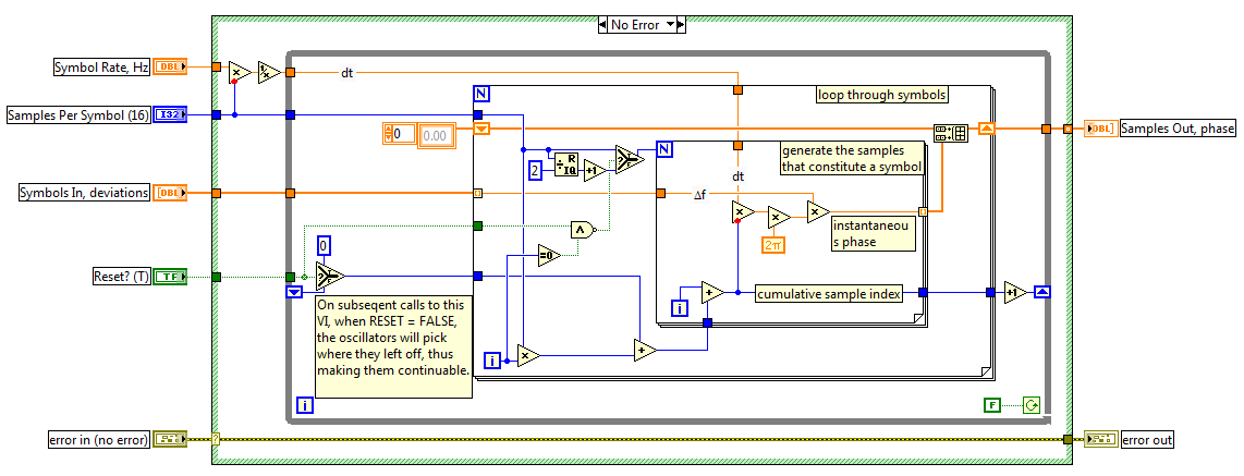
If you open MT modulate FSK.vi, then mod_FSK modular Phases.vi discontinuous to generate in the discontinuous case of the structure of the case, you will see the following code.
You can see that when Reset is set to True (the default) and the external-loop for is in his first race, the inner-loop for work (samples per symbol) / 2 + 1 times (in your case, this number is 512 / 2 + 1 = 257.) Subsequently, the inner-loop for runs with 512 for each outer loop for iteration. This means that the first round fail to 512-257 = 255 samples, which causes the total to 255 less samples.
I don't know what is the motivation behind this design. As a test, you could connect in a constant False to Reset of the MT Terminal modulated FSK VI, which causes all the samples to generate.
Hope that clarifies it.
-
How to trace datetime against temperature table of waveform
Hi guys,.
I try to draw data from my table and to draw a time value date on the x axis and the value of the temperature which resemble 32.5 c
on the y axis on a cat of waveform. I'm new to studio measure, anyone have an example on how to proceed?
I have a loop that loop and gets the data from each row (time and temperature) and I want to draw in each loop, I leave,
If the graph will be a building, and the user can see until I read all the records.
Hi lil_racoon,
Thank you for the additional information. After looking at what you're trying to do, I think that the enclosed code will achieve your goal. Try to adapt it to the work of your application.
Thank you
-
With the help of this function I can take a 2d data table and turns them into an array of 1 d waveform.
If a table of 7 x 100 would give me 7 waveforms with 100 values of y in each.
The dt would be the same and the departure time would be the same.
For some reason when I use the waveform graph it is traced 7 waveforms, but charted only 7 points for each. It must be drawn however many values there is in each waveform in my example 100.
Without any data stored in your VI, I can't say how your array is configured. You use a table of index in parallel on each line. Maybe you should be indexing on each column.
In addition, your code could be done easily by using a loop For auto-index using the waveform and table 2-D. The only thing you need to do is to use transpose the table before the loop For the index on the correct size (columns or rows).

-
Table of waveform in time real Multi ground
Hello
I've attached a picture showing part of my code. What I'm trying to do is to create the exact waveform as "Cell pressure (kPa)", but in the x-axis in real-time. I created the "wave form" and that it does not work enough. This table will 'Y' to 'build the waveform"will contain 8 items and when I run the program,"Waveform"shows all the elements in a plot rather than in 8 different locations in a single diagram.
Can someone choose where I am doing wrong?
Thank you
Hoda
Hoda wrote:
Table of waveform isn't the time component. I need to show all plots on a graph and real-time
As you convert scalar data to a cluster to the chart, he has no information indicating the time. Missing time initial T0 and the dT for the time interval.
Outside your wire loop right now for the Xscale.Offset property for the graph node. Because your loop time is 1 second, you must set the DT. But if it was something else, you must set the XScale.Multiplier property as well.

-
How to determine the strict reference to the table of waveform
Hello
I want to change the properties of a waveform by programming. I used to get all references maps of waveform a function of range in my script VI VI. Then I typecasted references to more specific class (strict-single track) after this trial I was able set properties such as data history. Everything works fine but if I add a graphic that is multiplot, that this approach does not work.
The problem is that in the table of references, there is reference to a graph in multiplot waveform, and this reference is not possible typcast to the more specific category (strict-single parcel).
My question is: how to determine if the reference in the table is matching the proper waveform (single or multiplot) charts.
In the VI attached is a code that demonstrates my problem.
Thanks a lot for the replies
Jan
Thank you for advice. VI point 2 from your answer, I created and it works. The solution is attached.
If I understand it correctly. I need to know the type of chart to come.
My first idea was to create a VI in Drop that initializes all the graphics of VI on chart type independently.
But this solution is fine because I will only use graphics-single plot and multiplot(two elements).
Thank you
Jan
-
Hello
First of all, I use LV7.0. I pass data to a waveform chart. A two-dimensional painting converted to a cluster, and then passed to the table data. Graph properties are set to only show that a single conspiracy, but there is so many places on the map I can't make heads or tails of it. See attachment. Thanks for any help, as someone of you could provide.
What is the size of your cluster? That determines how many different parcels you have.
-
tables of fixed size in FPGA compilation error - how to implement a waveform control in an FPGA?
Hello
After being stuck for two days, please let me briefly describe my project and the problem:
I want to use the cRIO FPGA for iterative control of waveforms. I want to capture a full period of the waveform, subtracting a reference waveform period and apply control algorithms on this. Subsequently the new period of correction must be sent again for the output module OR. If it does not work, the captured waveform will look like the one reference after several iterations.
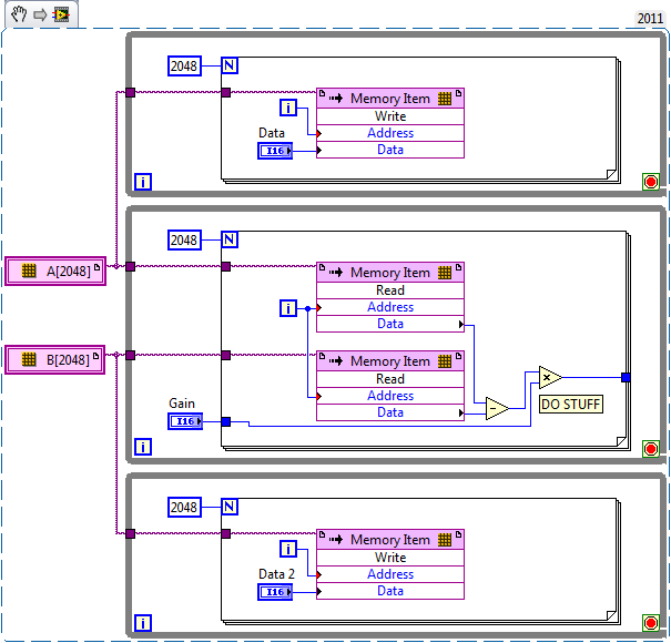
I am planing to create an array of size fixed for the capture and the reference waveform (each around 2,000 items for a given period). I use so 2 paintings of each elements of 2000. I use the function 'replace the subset of table' to update each element captured in the loop sampling and a feedback for each table node to keep in memory (I also tried shift registers, but then the berries do not have a fixed size any more and I can't start the compilation process).
If I try to compile the FPGA vi, I get the following error:
Details:
ERROR ortability:3 - Xilinx this application runs out of memory or met a memory conflict. Use of current memory is 4167696 KB. You can try to increase physical or virtual memory of your system. If you are using a Win32 system, you can increase your application from 2 GB to 3 GB memory using the 3 G switch in your boot.ini file. For more information, please visit Xilinx answer Record #14932. For technical support on this issue, you can open a WebCase with this project attached to http://www.xilinx.com/support.
"Synthesize - XST" process failedBefore I added berries to my code I could compile the FPGA without problems. So, it seems that the tables are too big for the FPGA. :-(
Therefore, I would like to ask if there is perhaps a better method to implement my problem in LabVIEW FPGA? How could avoid the tables to save my waveforms on a period?
Thanks a lot for your help in advance.
Best regards
Andreas
Unfortunately, the LabVIEW FPGA compiler cannot deduct stores shipped from berries (yet). When you create these two large paintings, you are creating essentially several registers very, very large. Just by looking at your picture, I guess that there are at least 4 copies of each of the tables.
You want to use LabVIEW FPGA memories instead. You can create memories outside the loop and then read/write them where you are currently referencing the berries. The only change that you really need to do is to break down your treatment in scalar operations. I have attached a simplified version of your plan, I hope it helps. Let us know if you have any other questions.
-
How to use table 1 d of waveform in the Matlab Script
I use Lavbiew to make the classification of Vibration signal.
The first problem I encountered is the form of incorrect data.
The output signals are 1 d arrary of waveform. I don't know how to use the Matlab Script.
is someone can help me with this?
I really appreciate your help.
Hey beauzhang,
I hope that you are well today. It certainly seems that we lack in some problems with the different sources and data types of wells. LVM VI Express load you have emerged from a table of waveforms. So we would need to do a few things. First of all, we need to ignore the range of interests, and we must get the waveform data elements table.
I have provided an example of how we can extract the waveform in position 0 of the table and then pass the array of data values to the script node Y. I have configured the entry of the data of a table 1 d Reals node (by adding an entry and then the right of entry and select choose data type.)
If you are interested in getting the values Y and build the table like you did in the script, you need to implement a different subset of table and looping mechanism in LabVIEW code to move each item to the script individually. However, I would recommend working with the entry level instead.
I hope this helps!

Maybe you are looking for
-
referencing of cell to another slide in keynote
How to reference a cell on a different slide in Keynote without having to type the name of the actual slide # and table.
-
Cannot burn CDs on Satellite Pro L10
I have a Satellite Pro L10 and impossible to copy data files to DVD/CD player. I go through the process by using the Editorial Assistant and it appears to download the files, but finishes with a screen that says "cannot complete the CD Writing Wizard
-
Problem with "contactless control."
1. it's all fine until yesterday when I was watching a YouTube video on my phone - "Touch control" started appearing right in between every single video I watch assuming I used the expression of launch. I recycled the couple of words of launch times,
-
How to convert labview 5.1 for 2011.
Hello I would appreciate if someone can convert labview 5.1 attached file to Labview 2011. Thank you Ganesh
-
help please really trouble running traktor pro2 without audio drop-outs because of the bios? limitation of the CPU? or usb drivers? I'm running on windows fully updated 8.1 and entirely bios update I have upgraded to 8 GB of memory to try to help and