Ridge detector malfunctioned.
Hello
I'm working on a project in which I want to calculate the rate of certain signals. I used the Ridge detector to detect the peak of the wave.
The Ridge detector works properly, but after some time as 40 seconds it starts counting the noise (which is less than the value of the Amplitude, and which was previously not count), I don't know the reason for it.
Can someone pls help me solve this problem
Thank you v.much
Hello
Finally working on the first vi I found the solution to my problem
The reason why I got for the evolution of the value of the rate was this picture filled, i.e. with time, the table gets more and more values and he took the time to work on it and therefore the vi give erroneous results in the rate.
I finally limited the value of the table and then past this range limited to the consumers section of producer for the calculation and then it worked correctly.
I ask everyone to answer me if I took the right path for the solution.
Thanks to all who have helped me get a solution.
Concerning
Tags: NI Software
Similar Questions
-
Ridge detector does not properly
The Ridge detector not give me the right places. The main file is called activation time. I use the probe but cannot understand why im getting the wrong places. Thank you in advance.
Your Ridge detector seems to work just for me. I rewrote the vi to make summits that were detected more easy to see. You put them all into a 2D array, which resulted in many many zeros. I have grouped the data in a table of clusters. Each cluster contained a table of the peaks for each line.
-
location in the Ridge detector indicator
I went through the context help for peak detector. I force understand the importance of the location indicator. Can someone give detailed information on how to find places of any input signal. ?
If my proposal here:
If you have another type of Signal, describe it or show it.
-
LabVIEW Ridge detector - fails the simple test?
Hi people.
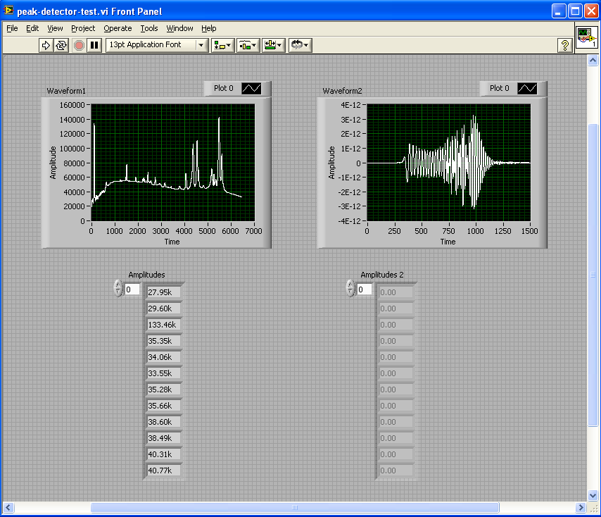
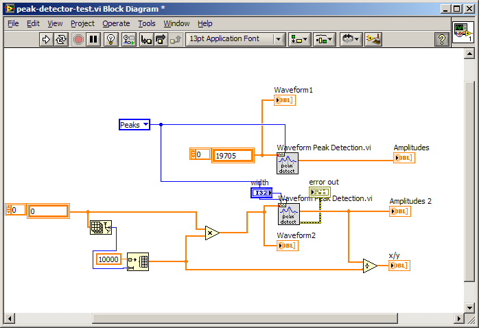
I tried two different spectra for the LabVIEW waveform peak detector (LabVIEW 8.5). It works fine, the other not, and I'm trying to understand why. VI and attached screenshot. I've hardcoded the bays so you can just run the VI. Any thoughts?
Thank you
Don
Hi Don,
Seems to me that the values are all simply too weak. But it's weird that there is no error generated.
I don't know if this solution will work for you or not. But I tried something on a whim and it seems to work.
The only thing I can guess is that the numbers that you were simply too small for the algorithm to work.
-
Hi all
I have problems trying to work with the Ridge detector tool... I have a file which contains 17 columns, that the first's time and the rest are data... I split and now Im trying to find the vertices of the first wave... I'm looking around and I find that it is only something bound on how the Ridge detector to receive data. IM now trying to convert the files again in a table, but only inside labview and I think that will solve this problem... but I can't.
Please if someone could help me I will be really great
In the attachments, you can find the .vi file and the excel file to run the program...
Thank you...
In Excel, I save the .csv file in .txt file and then do something like shown in the attached VI by reading the file using "reading of the File.vi worksheet. This way, you have full access to real values, including the table of time within the LabVIEW program... Don
-
Hey all,.
I need to use the crest detector, but labview8.5 said (NOT in the base package), which can make?
Best regards
If you have only the base package, you will not have the Ridge detector, so you need to find something else out there, such as already mentioned. Your version of LabVIEW is displayed when you select help > about LabVIEW.
Your series read work at all? You are able to view the signal? You start with that and then move forward. Attach images of a block diagram with everyone says about what your problem is.
-
Hi all
In my application, I'm analyzing a beep.
I used the spectral measurements vi for the FFT peaks.
Now I want to know the number of instances in which amplitues is over a certain limit, say 0.01.
Since I'm not an expert, I could really use some help.
I enclose my vi with a sample sound file.
Thank you
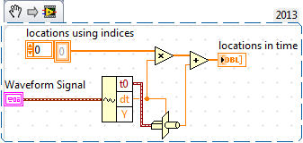
The result of the power spectrum is an array of clusters. Each cluster has three elements: f0, df and a variety of sizes. Ungroup all elements, use the table with a ridge detector function. Multiply the 'locations' with df and then add f0. The resulting table contains all vertices with the configured threshold already set on the frequencies to migrate.
Norbert
-
Subtraction and the determination of the base
Hi everyone - I need help to determine how best to make a determination of the base then subtract leaving just the tops. My data are profilometry measurements on a substrate surface. As you can see in the table below the substrate surface is pretty simple but not lying flat on the scanner table. I'm looking for a simple method identify the linear base line, then he subtract from the raw data, leaving the four peaks with essentially a zero/horizontal) basis. Then I can use the Ridge detector to identify the peaks and their locations so that I can make additional calculations (especially area of the PEAK and average maximum height).
Any suggestions on the best way to go about this?
An polynomial fit using the "less absolute residual" is relatively sensitive to outliers and seems to work quite well in this particular case.
See if it works for you.

-
How to find the crest of a curve of best polynomial form
Hello
I'm relatively new to Labview. I need to find the value of x corresponding to the maximum value of a better curve adjusted to a set of values there.
A typical dataset that I will work with is a table of about 15-30 y-values that are equal distance from known x-values (I have attached a file .lvm for an example of values y and x values), and it will be a fairly well-defined Summit.
The way that I do currently is to use the curve express vi, with a polynomial curve of 10 order, and then by converting the best adjustment line to an array of values using array Max vi Index to find the peak value y and wiring its index in a table of x values to find the position corresponding to the peak. I enclose my vi that does this.
The problem with this method is that I can't get the accuracy I need (because the values of x are spaced by 0.15, I wish that the precision of about 0.01).
I also tried out the best integrate a node formula coefficients (from the curve express vi) and then run a loop of x than aircraft values more accurate data points, but I had trouble getting the curve of this method to match the better to express vi curve curve.
Do you have any suggestions?
Call it what you want, but you're smoothing or filtering your data. It will pass the height and location of your apparent peak. Instead of trying to fit all of the data, you must use a mobile window where you set a subset of the points to a polynomial and check for a pic. That's exactly what the Ridge detector VI. I'd like to see if this VI - what are looking for before you go through the gymnastics of the polynomial. In my example, I remove the maximum amplitude peak and find its location. The location returned by the peak detector is a fractional index, so you can use interpolation 1 table D to find the corresponding x position. If you stay with the polynomial in the form, discover all of the polynomials screws, they are a snap to find the zeros of the derivative and other.
BTW, unless you really know the underlying model for your data I personally would be questionable estimates of precision that are 1/15th of the point spacing. 1/3 or 0.05 he pushes IMO.
Edit: 1 K apparently.
-
How to rebuild the waveform with zero new and create histogram type of waveform?
Hello everyone, I have an application where I need to rebuild a waveform using some amount of 'x' of the data samples. the conditions are:
1. the new zero of the new waveform is peak value frm the old form of wave., allows to assign this value of y s.
2. based on this peak value, I have to draw points of sampling (y - t) and (y + t)...
the waveform above may look like a histogram, but isn't exactly a histogram... can anyone suggest a concept?
I'm not able to take the time to "throw in a sample VI.
But if you look at the help file get the subset of waveform, you will see that he has all the inputs you need.
There is an enum constant that allows you to choose samples or time. I would say that the samples since this is what will come from most of the table Max/Min detector or Peak live
There is a sample start time. Put in the value of your Ridge detector less t.
There was a time. Put in the value of t 2 times.
If t is the time, you may need to convert to samples based on your sample rate.
-
Input analog continuous USB DAQ find amplitude peak to peak
I need to know if there is a way to use the crest detector when you do an analog voltage input. I use c# VS2005 and 8.6.
Hi jsheridan,
Have you looked at the Ridge detector example that comes with Measurement Studio? The c# example can be found here: C:\Documents and Settings\All Users\Documents\National Instruments\MStudioVS2005\DotNET\Examples\Analysis\PeakDetector\cs (assuming that you have installed on your C drive :).
The example generates a waveform and uses the PeakDetector class to detect the peaks. You can take this example and modify it to support what you are doing, or just put some functions in your code. The detector function takes an array and outputs tables of places, the amplitudes and the second derivatives of the peaks and valleys in the array passed to it. If you prefer to use all the time, you could just do a ridge detection after each reading some or all few seconds so that you make a lot of unnecessary calculations.
-
Detection of peaks of waveform data
Hi people.
It is probably obvious, but I can't understand it. In the attached VI sine wave detector summits are determined from a simulated signal. I want to be able to do the same thing with a waveform data (DBL), but it won't let me. How can I extract the signal of the LDM to feed the rest and make the waveform work VI right Ridge detector?
Thank you
Select this option.
Use of DDT, found in the range of Signal handling, to change the dynamic thread in a waveform.
Bob Schor
-
Converts the audio signals of the mydaq in discrete values
Hi guys!
I'm currently building a project that accepts mydaq audio signals. I wanted to analog signals it have descrete peak values. Is this possible? I intend to use the discrete peak values and sum their place by using a registry change instead of the peaks. I think it is easier.
Any suggestions would be helpful. Thank you very much!
"".. "in the end we all hopes"...
FalseHope wrote:
Yes it detects peaks. but I can't use the peaks detected for something else. He's right there showing me the summits. But I wanted to use these pics for something else, and then to summarize. If there is anything I can do in the peaks detected so that I can use it and summarize, please tell me.
Yes, the Ridge detector shows you where are the tops. Now use a loop FOR autoindex on where are the tops for the level in those places. Now you have a table to the top. You can then use add table items to add them together.
-
How to index a table on multiple sites?
Hello
How to index a table on multiple sites?
I searched this issue and was not able to find the answer. I understand that it can be done with loops, but I don't know how.
I use the detector of crete vi for frequency domain data collected a VNA (s2p) file. The products contain a table of amplitudes and a table of locations. The problem is that the locations refer to the index of table of amplitude, which is not the same as the frequency. My idea is that I can use this output of the places table to index the frequency to the detected peak frequencies table and then draw these, as well as some analysis data and manipulation on them. Currently, I can do this only by consulting table on the front panel.
The entrance to the peak detector is currently a table 1 d of the scale (what is the problem?).
I also looked at the supply frequency & estimate VI, but this VI seems only exit of scalar data for the largest peak, not exactly what I'm looking for.
Thanks for your help.
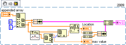
You have a second table for the tested frequency? If so, then you are right that you just need to index this table with the indexes by the Ridge detector. Use a loop for. Automatic index to the index, use index in array to get the value of the frequency and autoindex on frequencies.

-
How can I catch a wave and measure asymmetric peak?
A profilometer using the topology of a deposited material surface can be measured. I want to design a program to read in the raw data of these profiles files and then perform an analysis that will extract the distribution in the heights of peaks/troughs and the distances between the peaks. Reading data, manipulation of tables and producing output/plots files with that I'm fine but the problem I have are as to what analysis tools can be used on these asymmetric waveforms. I was thinking about a form any signal processing technique, but I'm not sure. I have attached a profile example for one of my samples to give an idea of what I am working with...
If it is representative enough of your data, I would first take stabbed using the detector tip a LabVIEW VI (Signal Processing-> operation of signals). There not much noise at all relative to the size of your pics (if we talk only about those visible here), so you could just smooth out your data with a Savitsky-Golay function (or such) to exit the small move of random noise, offset all of your points to make positive, set a width value and the crest of the reasonable threshold and get there.
Now, if you have a huge hollow as in the file you sent, you may miss a lot of pics (even once, I don't know what are your criteria for a 'Summit'). If that happens, I would say looking at data upside down to find your valleys as reverse 'summits '. At this point, you can go right back, connect the valleys with lines and subtract these points from your data to a pseudo-base and run the VI Ridge detector again (you probably can go much more sensitive with your adjustment of threshold because you took most of drifting in the very long term). You should have now identified all of your points of peak and Valley on axis X. return the original data to determine the heights of peaks with some basic algorithm you want to use (linear between valleys, Bézier curves, etc.).
That's how I would attack it generically. But it's a very common situation in probably all science and engineering fields. Isn't there some geological no - power of data standard method generally agreed criteria for your problem?
Cameron
Maybe you are looking for
-
HP pavilion n201se 15: how to partition my hard drive with recovery DVDs
HelloPlease I now have my recovery DVD to my Hp laptop and I had already delete the partition of recovery on the laptop, so now I want to do the new facility with my DVD recovery and the partition of the HARD drive in two, but it seems that I do not
-
I have a new iPadPro and am locked out
Thought that I had put my password - but she doesn't recognize me and I can not reset with iTunes because there is no software update with iPadPro. Suppose I'll have to Mac Store? I'm really sad: Mac used to be 'plug and play' no more (owner since 19
-
HP 430 G2: Freezing of the touchpad, randomly when I use my laptop
Hello I bought this phone 6 months ago, and this problem starts for 2 or 3 months. I tried the synaptics driver version 17.0.18.8, 18.1.8.1 and 18.1.15, all versions have the same problem Sometimes the cursor freeze, sometimes the cursor moving aroun
-
Hoe komt het dat als ik p.c. opstart ik lack keer het bericht dat the system treat is hersteld van een ernstige hell. Of handtekening van of hell is: code 1000008e JIU. BCP1 BCP2 0000005 BD210CDC BCP3:AB9D287C BCP4 00000000 SP:3 OS Ver: 5 - 1-2600-0
-
N5010 0Xc00000e error after system recovery
Recently, I replaced the hard drive in my N5010. Using WIN7 USB recovery media that was created when I got to the machine (2011), I have been able to restore the pc to an original image with success, through the installation of the first use and per