Sample interval finished PCI 6071E scanning
Hello
We plan to acquire data of an array of 64 pixels linear photodiode using PCI 6071E. Suppose we take 64 x 3 samples our sample rate is 1 ms/s (for 64 channels of avian influenza) and each group of 64 samples are separated by a time interval T * (see photo).
Platform: WIN XP OS, DAQmx with C++, Int CLK
For the big T * > 50ms we can set the device to take 64 samples each time and reconfigure the unit and prepare for the next DAQmxReadAnalogF64.
For the smaller T * (say 2ms), the device may not able to reconfigure quickly enough that works properly. One can think of device configuration to collect samples of 64 x 3 and using external synchronization (using a delayed digital model) to care for the calendar
(see attached "Sub PDA::Acquire()" C++ code, which can be changed to use Ext. CLK).
but I post here in case any expert knows an easier way without adding hardware.
The ideal solution, we expect to send a trigger for each set of 64 samples and controls the delay between each set of acquisition between triggers, but it is not possible to obtain simply by using this device.
Thank you very much in advance,
eLions.
Tags: NI Hardware
Similar Questions
-
Hi, we intend to use the PCI-6071E to measure signals of tension of two photodiode arrays (PDAS). Detailed implementation is the following:
Mode of operation: input analog, acquisition continues, external clock of sampling/analysis (rate ~ 100KS/s), external start trigger
Software: C++ based on NI-DAQmx
Start by the example code "ContAcq-ExtClk - DigStart.c.
We intend to use a single analog channel for PDA. Each PDA sends a series of singals trigger (which will serve to 6071E as sample clock), an edge from low to high for each pixel. The experience is configed such that most likely, we can use the same start for the two entries of PDA, but their clocks in the sample may have a relative delay (typically a few microseconds). We certainly prefer to acquire the data of each input channel with respect to his own sample clock.
Is it possible to do? How?
Our initial estimate is to schedule two TaskHandlers, each with its own sample clock configed (maybe start trigger as well) and start/play/stop almost at the same time. This seems reasonable? If so, our ultimate goal is to work with two more PDA (a total of 4). What is the limit of the number of sample clock so all acquisitions are made sinmutaneously?
Thank you for your comments in advance and your solutions.
Kunyan
Hello Kunyan,
Unfortunately, with the 6071E you only PFI monotube (PFI 7) for the sample external clock use, as a single line PFI to HAVE start the use of the trigger. You can see 6071E specifications to see these lines. You will most likely run all your PDA out of the same sample clock and starting to trigger, unless you do not want to use several DAQ cards. I hope this helps.
Kind regards
-
NEITHER 3202 - SAMPLING INTERVAL ADJUSTMENTS
Hello!
I need clarification on the concept of sampling interval wrt nodes NI WSN (3202, 3212, 3226) training and even with my kit. I list the approaches that I have known,
- Approach I: in Structure case 'Node target VI'--> 'Start '. Choose the mode "VI Driven" and together with a constant interval sampling.
- Approach II: In the case 'Node target VI'--> 'Start' Structure. Choose mode "Host Driven" and the sampling of sets interval via "user Project dialog box" (*.lvproj), choose particular node, do a right click-> properties-> tab node-> change the number in the collection interval box. "»
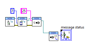
- Approach III: Using the API host WSN, something as pic shown sideways
Question 1: I tried this III, with "VI Driven" approach, does this independent approach of mode affect you?
- Approach IV: In 'Target node VI'--> placing 'ConfigNode VI' and set the sampling interval according to the logic of the user in "Sample" and other Structures of the case. [Interval sampling mode: VI led]
Question 2: Considering III feasible approach in mode 'Led VI', did any priority is offered by node approach III against approach IV?
[For example.] I set my Interval(say 45 <->60) of sampling to change in the order through certain events trigerred (BatteryLevels, LinkQ, SampledDataRange) and using VI host suite III approach I want to change the sampling interval (say 30) for a while. [So now sampling 30 sec interval remains static or it keeps changing (45/60) to 30 when the target node running sample structures & received Msgs.]Question 3: We have the chance to change the sampling for each channel (AI0... intervals AI3) or in groups of two channels and even with digital channels, if there is no restriction of internal hardware ADC/MUX invloved let me know.
[For example.] If my sample data (range: 1-6 volts) to channel AI0 grave in particular area (say, 1 - 3V), work are perpendicular, but if it falls in the range (say 4-6 v) I want to change the sampling interval, while other channels (AI1... [A13) remain the same, regardless of either]Hi PP_BABU,
This would work except that it might be difficult to corelate the sample # in the message to the user for the IO AI1 variable. A better approach may be to enter the data locally and combine multiple samples in a user-defined variable. You can change the AI1 data to a string, and then concatonate several in a larger string. Then send bursts of data. That should help with the battery life you could send each second instead of constantly backdata.
Provided that the user has taken, there is no limitation. You just need to drop a basic I/O node and select digital i/o > User LED , then right click on the same I/O node, then select change write.
See you soon,.
Brian has
R & D Product Support Engineer | WSN/network DAQ
National Instruments
-
Greetings,
I have two questions probably related. A question is that I am trying to use an interval to retrieve data of a sample continuous DAQ cards (I have tested this on a 6361 and also a 16XE-10). When I run the code, I specify a sample rate and a sampling interval to choose the number of samples to receive. The number of samples to read door should how long takes it from the read operation, however, the time required to complete this operation is never my specified sampling interval which doesn't make much sense to me. In addition, the dt for my data is always 0, as if she doesn't really know the sampling frequency. This is probably a stupid mistake where I do not forget a set, but maybe someone can see my error and report to me. Thanks for the help.
Attached is an example vi that must show the question.
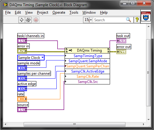
The sample default calendar type is "On Demand" and it doesn't seem like you have changed it. Why not just call DAQmx Timing.vi to set the clock sample settings? It encapsulates the property nodes that configure the sample clock calendar:
Best regards
-
Effectively change the continuous sample mode sample mode finished
9188 chassis, modules (HAVE them), 9 of Labview
I want to acquire continually (and display) given at a fast rate to date, and then when a 'trigger arms' State is detected, the switch to finished hardware, triggered task with pre-trigger samples with a minimum loss of perceived as update rate.
What is the best way to do
Thank you
Collin
I started my answer a long time ago while waiting for a reboot and am just finally getting back to it. I see that you got another another answer in the meantime. On the outbreak of reference, here is another link that might help some: Acq suite w / Ref Trig
I did have not tinkered with reference trigger a lot, so not sure what is meant in the link above about the task being an acquisition over 'the end'. Maybe the task continues to fill the buffer just before there about to overwrite the first sample of pre-trigger?
In any case, my original thought the whole thing was on another track. If the trigger Ref works for you, it'll be easier. But if Ref trigger causes the acquisition of stop * and * you really need to keep it going permanently, then consider the things below:
-------------------------------------------------------------------------------------------
Passage of the continuous sampling done will require the judgment and the reprogramming of your task, and you will have a 'blind spot' of data loss, while what is happening.
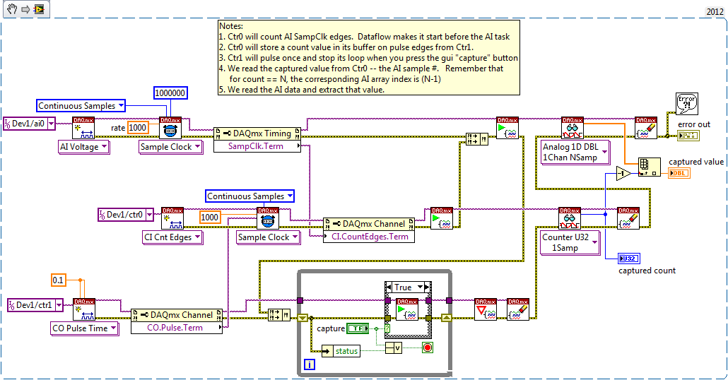
An approach that I think is to stick to a sampling WAS continuous, but also set up a counter task that can count it HAVE examples of clock and capture on the trigger signal. The captured value of count will be HAVE it taste # when the trigger has occurred, and then easily post-process you your data HAVE to find the subset that represents your data before and after the desired trigger.
Here is an excerpt of what I mean 2012:
-Kevin P
-
How to power supply of NOR-DAQmx PCI-6071e using Visual C++?
Hello, I am a first year student Bachelor do a team project for school and I am completely stuck. The laboratory on campus has allowed us to use their PCI of NOR-DAQmx-6071e card and the school provides free Visual Studio 2008. We try to grasp the card voltage levels in Visual C++, but we do not know what code to use. In addition, we cannot buy Measurement Studio Professional (or a standard, incidentally). Can someone explain please how to read voltage levels? Code example would be much appreciated.
There is a sequence of function calls required to create a task. This document goes through the steps needed to include in a job. When you install the DAQmx driver, the examples are also installed and can be found as described here. It will take a few changes to ANSI C examples to use in Visual C++ that are described here. Hope this helps!
-
Maximum sample clock of PCIe 6537 ANSI C
I'm programming a card PCIe-6537 with ANSI C. The application uses sampling continuously, with a reminder to analyze the samples.
The maximum sampling frequency should be 50 000 000 samples/s. The internal sample clock is assumed to be 200 MHz/N where N > = 4.
I can run to 40.000.000 samples/s (N = 5), but if I put the sample clock to 50,000,000 samples/s (N = 4), the callback is never called.
I created the task with the following calls.
DAQmxCreateTask (TaskName.c_str (), & m_TaskHandle);
I calculate $thisline = ' Dev1/portX/BEHLULI for X = Y = 0.7 and 0.3 and I call for each
DAQmxCreateDIChan (m_TaskHandle, ThisLine.c_str (), "", DAQmx_Val_ChanPerLine);
Then I put in place of the sample clock. It works:
DAQmxCfgSampClkTiming (m_TaskHandle, NULL,
40000000, DAQmx_Val_Rising, DAQmx_Val_ContSamps, 16000000
);It's not:
DAQmxCfgSampClkTiming (m_TaskHandle, NULL,
50000000, DAQmx_Val_Rising, DAQmx_Val_ContSamps, 16000000
);I save the callback so:
() DAQmxRegisterEveryNSamplesEvent
m_TaskHandle,
DAQmx_Val_Acquired_Into_Buffer,
4000000,
0,
NI6537_EveryNSamplesCallback,
This
) ;The callback increments an integer that came out when I end the program by pressing ESC.
Y at - there a trick to getting the sample clock to work at the rate increase? Or it is limited by the PC somehow, so that the callback just won't happen to 50Ms/s?
Frank
Frank,
You can check and make sure that the BIOS of your PC has been updated to the latest revision. This can have an effect on the maximum transfer speed on PCI Express.
There are some cases (depending on the maximum packet size allowed by the chipset of your computer) where a PCIe-6537 cannot acquire 32 channels of data at 50 MHz. It's strictly a limitation of the PC. If your BIOS is up to date and it still does not work, you can try your code with the PCIe-6537 on a newer computer?
Keith Shapiro
National Instruments R & D
-
on the sample rate of PCI-6723
According to the specification of PCI-6723, faster sampling rate is 45kSample/s, 32 channels working simultaneously. But he's always fine when I put the sampling frequency to 200kSample/s, 32 channels working simultaneously. This configuration will damage the material?
Ok. I assume you mean update rate of sampling frequency not. As long as you use the onboard buffer you can reach 204Ks/s 32 channels. Since you do not get an error the device and things work it is probably what you're doing.
You had asked the rate could only be achieved you would have been a mistake. And the material would not be damaged by incorrect update rate adjustment. You're ready to go!
-
Hello world.
I have a question.
In Virtual Center there is a performance tab, where you can consider the graph with the CPU.
I see that there are some statistics of the use of the CPU: minimum, maximum, and average.
It also shows that the refreshing interval is 20 seconds
One knows how many saples are taken as 20 sec? (it seems that there are more samples then 2 because the average value is not the average of the Max and min.
Can we change it?
See you soon,.
Konrad
You are welcome.
My understanding of this is the max and min values average that the values of the whole army over time period shown on the display, in this case during the last hour.
If you highlight the value that indicates the percentages for the entire army, (I think that its Purple in your screenshot), you should see that the values in the graph equals text values in the table below the graph.
So, when he says real-time display, it isn't at every instant, real-time, but a graph of a sample taken every 20 seconds and then displayed on the graph 20 increments of a second over the last hour.
In other words, every 20 seconds it samples the host and then displays this value in the far-right (end of the graph). The last value is just that, the last measured sample.
The max, min and average value are these respective measures during the last hour of the graph you posted. You are quite right in thinking that the last sample cannot have different values for these measures at the same time. The only time they would have been the same is on the initial sample.
Another interesting note is that you can see how well the Scheduler is using and distributing the load on different cpu looking at this table. When you look at each of the varios indivdual cpu, you can see that each of the 4 cpu have very similar max, min and average values during the last hour, one near an average higher for cpu0. This is normal since it is the cpu when the service console runs on, and there will be a little higher this processor load, in General,.
12 VMs on 4 processors with an average 30% CPU usage. Not bad, 3 vms by heart. They all uniprocessor vms?
-
How to set the sampling interval using DAQ hardware?
Now I have a sensor capability and hardware DAQ 24 bit (http://www.mccdaq.com/usb-data-acquisition/USB-2404-10.aspx).
The DAQ hardware has the 50kS/s maximum sampling rate. My question is how to define the range of data collection. For example, if I set the sampling rate of 2000, continuous sample mode, I use read.vi DAQmx in a while loop and set the "number of samples per channel" to 100. I want to plot these data over time using a XY Chart and also save this data. So I add a 'Medium' function to get the average of 100 samples per each loop (medium, there are 20 release of data per second). But when I put a 'number of samples per channel' much more small (for more data per second), there are a few problems. It seems that the program cannot read the data as much and get the average at a higher frequency. I don't know where is the problem. Overall, the collection of data more frequently? Maybe I didn't articulate my question. I'll upload a simple program later if necessary. Thank you.
-
Hi people
Does anyone know of a way to define the analysis sample select delay (by: field) 1 min for periods of time longer than one hour (see screenshot). We would like to have granularity 1 minute for periods up to 4 hours.
I have read through the doco and can't find a way to do this. If anyone knows how to do this, it would be much appreciated.
Hello
Please see private message that I sent you.
Thank you
Zviad Polak
AppSpeed Support
-
How PCI confugure 6071E as a counter
Hello
This may seem like simple problem: we have a 1 kHz sinusoidal topic (0 - 5V), each pulse can differ a bit, and it has about 9500 cycles. The goal is to know how many cycles (edges of low to high) are there in the second 9.5 analysis. We try to use PCI-6071E as meter, the sinusoidal signal is connected to GPCTR0_SOURCE. It seems to give the wrong answers by using the following program. Could someone please suggest the correct way to do it? Thank you
/*********************************************************************
* ANSI C++ program: 24-bit digital counter
* To compile in cmd.exe "cl /EHsc PeakCounter.cc.
*********************************************************************/#include
#include "NIDAQmx.h".
#include
#include
#include
#include
#include
#include
#pragma how (lib, "NIDAQmx.lib")
#pragma how (lib, "odbccp32.lib")
#pragma how (lib, "odbc32.lib")using namespace std;
#define DAQmxErrChk (functionCall) if (DAQmxFailed (error = (functionCall))) goto error; on the other
int main (void)
{
error int = 0;
TaskHandle taskHandle = 0;
uInt32 data;
char errBuff [2048] = {'\0'};/*********************************************/
DAQmx Configure Code
/*********************************************/
DAQmxErrChk (DAQmxCreateTask("",&taskHandle));
DAQmxErrChk (DAQmxCreateCICountEdgesChan(taskHandle,"Dev2/ctr0","",DAQmx_Val_Rising,0,DAQmx_Val_CountUp)); PIN - PCI6071E, initial = 0
/*********************************************/
Starting code DAQmx
/*********************************************/
DAQmxErrChk (DAQmxStartTask (taskHandle));printf ("without interruption of the poll. Press Ctrl + C to interrupt\n");
While {} (1)
/*********************************************/
Reading DAQmx code
/*********************************************/
DAQmxErrChk (DAQmxReadCounterScalarU32(taskHandle,10.0,&data,)); read the counter 10 sec delay
printf ("\rCount: %d", data);
fflush (stdout);
}Error:
puts("");
If (DAQmxFailed (error))
DAQmxGetExtendedErrorInfo (errBuff, 2048);
If (taskHandle! = 0) {}
/*********************************************/
Stop DAQmx code
/*********************************************/
DAQmxStopTask (taskHandle);
DAQmxClearTask (taskHandle);
}
If (DAQmxFailed (error))
printf ("error DAQmx: %s\n",errBuff); ")
printf ("end of the program, press the Enter key to quit\n");
GetChar ();
return 0;
}If you do not use the 6071E to count periods of sinusoidal signal, you can do this by configuring an analog trigger then the edges of the event of analog comparison. Analog comparison event is a digital signal generated by analog trigger circuit and again permanently with your sinusoidal signal once the task has started. The downside is that you must use your analog subsystem to create the trigger signal.
For an example, see here.
* Edit, I just noticed that you develop using the C API. If you don't want to go in this way and need help implementation of the C API, let know us. The general idea is exactly the same as what I described, and which is implemented in LabVIEW code which I have shown you.
Best regards
-
Duration of the individual sample - OR-6220 and NOR-6723
Hello
We are acquiring data through NOR-6220 and NOR-6723 Renault in our laboratory. The data acquisition process through Data Acquisition Toolbox of Matlab, where we put the sampling rate of the analog inputs to 10 kHz - or 0.1 sec per sample. Now, we wonder what is the time of the sampling process, i.e. the period during which an individual sample. Is there an average process for the duration of the sample (0.1 s), or during a window much shorter? In the latter case, how would know us the exact duration, and it would be possible to control it?
In our case, we see resistance jumps in our system. Even if we get a range of resistances, we suspect that these jumps can actually be between two distinct levels; It is possible that the process of averaging during the sampling results in obtaining intermediate values between these resistances. Have a shorter window of sampling would be useful in addition to interpreting the results.
It seems that this could be a trivial question, or who might be a Matlab thing rather than a thing of the card. Bear with us in these cases; We have made an effort to research on the problems on the forums and elsewhere
 . Thank you!
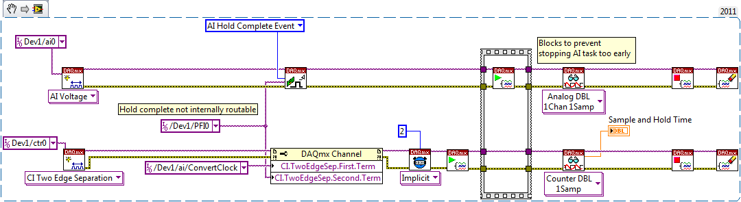
There is a sample circuit and hold on the device. The clock to convert marks the beginning of the sample interval, while the complete signal of cale HAVE mark the end.
I don't know if the waiting time is nowhere specified, but you should be able to measure like this (example LabVIEW... I don't have MATLAB or the Data Acquisition Toolbox unfortunately):
On my PCIe-6351, I get a waiting time between 440 and 450 ns. The 6220 can be different, but I hope that gives you an estimate. This setting is not adjustable.
Having said all that I don't think it's relevant to your question. If your input signal varies between different levels and you want to try that once it has established a new value, you must ensure that the task of IT is synchronized to what generates the signal.
Best regards
-
Sampling frequency for the output of an acquisition of data USB-6211 card?
Hello-
I use a CGI CMOS FireWire camera to read an interference figure, then using a transformed of Fourier transform spectral interferometery (FTSI) phase recovery simple algorithm to detect the relative phase between the successive shots. My camera has a linear 28 kHz scan rate, and I programmed my phase retrieval algorithm take ms ~0.7 (of a trigger of camera at the exit of the phase). I use the live signal to control a piezoelectric stack, by sending a voltage single sample to the analog output of a data USB-6211 acquisition card.
Send this output voltage increases the time of my loop 4 m, I would really like to achieve a 1 kHz or better sampling rate. Is the problem with my DAQ card or with the processor in my computer? The DAQ cards of NOR can support these speeds?
Thank you
-Mike Chini
Hey Mike,
With USB, your loop rate will be around or under 1 kHz, even on the best of the systems. USB has a higher latency and less determism PCI and PCIe. You can get rates AO one much better sample on a PCI card, potentially a PCI-6221. We have a few HAVE points of reference for targets of RT for PCI, / AO in a loop, you should be able to get similar performance in Windows, but if you do a lot other treatments may suffer from your local loop rates.
Hope this helps,
Andrew S
-
Encoder triggered Acquisition (Single Channel N samples)
Hello Internets,
I am an inexperienced user of LabVIEW, I'm trying to set up a system in which blood samples are taken when triggered by a digital pulse.
I'm sampling using a PCI-6250. I have an updated encoder in place that emits a digital pulse once per turn. I would possibly take about 1000 samples in a very short time triggered by this time by pulse rev.
The problem I have right now is that I seem to get a lot less reading I expect otherwise, the LabVIEW program, I'm running also takes a long time to stop following my pressing the stop button.
The table fills also in a way that is strange to me, perhaps someone could it explain?
Thanks, any help would be greatly appreciated!
Hi Relaxidermist,
There are a few things in your current code that seems contrary to your goal:
"I would possibly take about 1000 samples in a very short time triggered by this time by pulse rev."
Assuming that you want to read 1000 samples for each received external trigger and you have several triggers coming, I would start by this example:
Redeclenchables analog input finished using digital triggering
I'll be the first to admit that he is not the most intuitive - on the M-series (like your 6250), use a meter to output to an acquisition really triggered. You could rearm task in the software, but this takes time and is prone to triggering signals are missing.
If you were on a series of X (63xx devices), the code you have is close, but you must make the following changes:
(1) use the clock embedded to your example of clock instead of the external signal for PPR source.
(2) make the task finished instead of continuous.
(3) enable the redeclenchables property - it is not available on your device of the M series (where workaround posted above).
Best regards
Maybe you are looking for
-
How do I refresh the page on the orientation using Blackberry 9800 "BOLD" change
Hello everyone, I'm working on an application in which I use both portrait and landscape. But the problem is that if I start the application in profile mode then it adjusts the image according to the style of portrait but I change mobile orientation
-
When I try to eprint by email directly from my photos on my iPhone 4, printing still fails. But I can go to my messages in my iphone mail and convey the same message to the same their e-print e-mail it works very well. Failure is somewhere in the (pr
-
How to edit files archived at ALL
Somehow all my files are archived, so are not appearing no no across devices. How to change that while they are everywhere? It is not intuitive.
-
Change the size of the text in the first 3 columns in a table
Hello I have a CS6 Indesign for mac with 340 pages and on each page document, there is a table with 4 columns.The document has no paragraph, stable, cell styles.Is there a script to change the size of the text in the first 3 columns of pt of 8.5 to 1
-
How to print a batch of photo in PSE 13 for mac?
I can't print a contact sheet or a pack of photo in PSE 13 for mac. How to activate this feature?