Sampling interval
Hello world.
I have a question.
In Virtual Center there is a performance tab, where you can consider the graph with the CPU.
I see that there are some statistics of the use of the CPU: minimum, maximum, and average.
It also shows that the refreshing interval is 20 seconds
One knows how many saples are taken as 20 sec? (it seems that there are more samples then 2 because the average value is not the average of the Max and min.
Can we change it?
See you soon,.
Konrad
You are welcome.
My understanding of this is the max and min values average that the values of the whole army over time period shown on the display, in this case during the last hour.
If you highlight the value that indicates the percentages for the entire army, (I think that its Purple in your screenshot), you should see that the values in the graph equals text values in the table below the graph.
So, when he says real-time display, it isn't at every instant, real-time, but a graph of a sample taken every 20 seconds and then displayed on the graph 20 increments of a second over the last hour.
In other words, every 20 seconds it samples the host and then displays this value in the far-right (end of the graph). The last value is just that, the last measured sample.
The max, min and average value are these respective measures during the last hour of the graph you posted. You are quite right in thinking that the last sample cannot have different values for these measures at the same time. The only time they would have been the same is on the initial sample.
Another interesting note is that you can see how well the Scheduler is using and distributing the load on different cpu looking at this table. When you look at each of the varios indivdual cpu, you can see that each of the 4 cpu have very similar max, min and average values during the last hour, one near an average higher for cpu0. This is normal since it is the cpu when the service console runs on, and there will be a little higher this processor load, in General,.
12 VMs on 4 processors with an average 30% CPU usage. Not bad, 3 vms by heart. They all uniprocessor vms?
Tags: VMware
Similar Questions
-
NEITHER 3202 - SAMPLING INTERVAL ADJUSTMENTS
Hello!
I need clarification on the concept of sampling interval wrt nodes NI WSN (3202, 3212, 3226) training and even with my kit. I list the approaches that I have known,
- Approach I: in Structure case 'Node target VI'--> 'Start '. Choose the mode "VI Driven" and together with a constant interval sampling.
- Approach II: In the case 'Node target VI'--> 'Start' Structure. Choose mode "Host Driven" and the sampling of sets interval via "user Project dialog box" (*.lvproj), choose particular node, do a right click-> properties-> tab node-> change the number in the collection interval box. "»
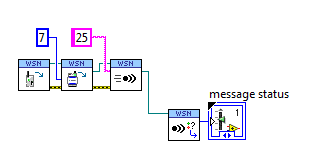
- Approach III: Using the API host WSN, something as pic shown sideways
Question 1: I tried this III, with "VI Driven" approach, does this independent approach of mode affect you?
- Approach IV: In 'Target node VI'--> placing 'ConfigNode VI' and set the sampling interval according to the logic of the user in "Sample" and other Structures of the case. [Interval sampling mode: VI led]
Question 2: Considering III feasible approach in mode 'Led VI', did any priority is offered by node approach III against approach IV?
[For example.] I set my Interval(say 45 <->60) of sampling to change in the order through certain events trigerred (BatteryLevels, LinkQ, SampledDataRange) and using VI host suite III approach I want to change the sampling interval (say 30) for a while. [So now sampling 30 sec interval remains static or it keeps changing (45/60) to 30 when the target node running sample structures & received Msgs.]Question 3: We have the chance to change the sampling for each channel (AI0... intervals AI3) or in groups of two channels and even with digital channels, if there is no restriction of internal hardware ADC/MUX invloved let me know.
[For example.] If my sample data (range: 1-6 volts) to channel AI0 grave in particular area (say, 1 - 3V), work are perpendicular, but if it falls in the range (say 4-6 v) I want to change the sampling interval, while other channels (AI1... [A13) remain the same, regardless of either]Hi PP_BABU,
This would work except that it might be difficult to corelate the sample # in the message to the user for the IO AI1 variable. A better approach may be to enter the data locally and combine multiple samples in a user-defined variable. You can change the AI1 data to a string, and then concatonate several in a larger string. Then send bursts of data. That should help with the battery life you could send each second instead of constantly backdata.
Provided that the user has taken, there is no limitation. You just need to drop a basic I/O node and select digital i/o > User LED , then right click on the same I/O node, then select change write.
See you soon,.
Brian has
R & D Product Support Engineer | WSN/network DAQ
National Instruments
-
Greetings,
I have two questions probably related. A question is that I am trying to use an interval to retrieve data of a sample continuous DAQ cards (I have tested this on a 6361 and also a 16XE-10). When I run the code, I specify a sample rate and a sampling interval to choose the number of samples to receive. The number of samples to read door should how long takes it from the read operation, however, the time required to complete this operation is never my specified sampling interval which doesn't make much sense to me. In addition, the dt for my data is always 0, as if she doesn't really know the sampling frequency. This is probably a stupid mistake where I do not forget a set, but maybe someone can see my error and report to me. Thanks for the help.
Attached is an example vi that must show the question.
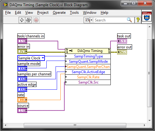
The sample default calendar type is "On Demand" and it doesn't seem like you have changed it. Why not just call DAQmx Timing.vi to set the clock sample settings? It encapsulates the property nodes that configure the sample clock calendar:
Best regards
-
Sample interval finished PCI 6071E scanning
Hello
We plan to acquire data of an array of 64 pixels linear photodiode using PCI 6071E. Suppose we take 64 x 3 samples our sample rate is 1 ms/s (for 64 channels of avian influenza) and each group of 64 samples are separated by a time interval T * (see photo).
Platform: WIN XP OS, DAQmx with C++, Int CLK
For the big T * > 50ms we can set the device to take 64 samples each time and reconfigure the unit and prepare for the next DAQmxReadAnalogF64.
For the smaller T * (say 2ms), the device may not able to reconfigure quickly enough that works properly. One can think of device configuration to collect samples of 64 x 3 and using external synchronization (using a delayed digital model) to care for the calendar
(see attached "Sub PDA::Acquire()" C++ code, which can be changed to use Ext. CLK).
but I post here in case any expert knows an easier way without adding hardware.
The ideal solution, we expect to send a trigger for each set of 64 samples and controls the delay between each set of acquisition between triggers, but it is not possible to obtain simply by using this device.
Thank you very much in advance,
eLions.
-
How to set the sampling interval using DAQ hardware?
Now I have a sensor capability and hardware DAQ 24 bit (http://www.mccdaq.com/usb-data-acquisition/USB-2404-10.aspx).
The DAQ hardware has the 50kS/s maximum sampling rate. My question is how to define the range of data collection. For example, if I set the sampling rate of 2000, continuous sample mode, I use read.vi DAQmx in a while loop and set the "number of samples per channel" to 100. I want to plot these data over time using a XY Chart and also save this data. So I add a 'Medium' function to get the average of 100 samples per each loop (medium, there are 20 release of data per second). But when I put a 'number of samples per channel' much more small (for more data per second), there are a few problems. It seems that the program cannot read the data as much and get the average at a higher frequency. I don't know where is the problem. Overall, the collection of data more frequently? Maybe I didn't articulate my question. I'll upload a simple program later if necessary. Thank you.
-
Hi people
Does anyone know of a way to define the analysis sample select delay (by: field) 1 min for periods of time longer than one hour (see screenshot). We would like to have granularity 1 minute for periods up to 4 hours.
I have read through the doco and can't find a way to do this. If anyone knows how to do this, it would be much appreciated.
Hello
Please see private message that I sent you.
Thank you
Zviad Polak
AppSpeed Support
-
Duration of the individual sample - OR-6220 and NOR-6723
Hello
We are acquiring data through NOR-6220 and NOR-6723 Renault in our laboratory. The data acquisition process through Data Acquisition Toolbox of Matlab, where we put the sampling rate of the analog inputs to 10 kHz - or 0.1 sec per sample. Now, we wonder what is the time of the sampling process, i.e. the period during which an individual sample. Is there an average process for the duration of the sample (0.1 s), or during a window much shorter? In the latter case, how would know us the exact duration, and it would be possible to control it?
In our case, we see resistance jumps in our system. Even if we get a range of resistances, we suspect that these jumps can actually be between two distinct levels; It is possible that the process of averaging during the sampling results in obtaining intermediate values between these resistances. Have a shorter window of sampling would be useful in addition to interpreting the results.
It seems that this could be a trivial question, or who might be a Matlab thing rather than a thing of the card. Bear with us in these cases; We have made an effort to research on the problems on the forums and elsewhere
 . Thank you!
There is a sample circuit and hold on the device. The clock to convert marks the beginning of the sample interval, while the complete signal of cale HAVE mark the end.
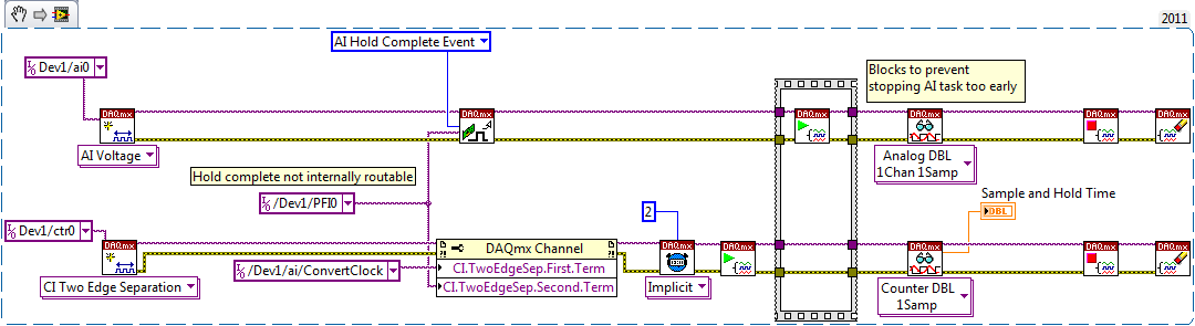
I don't know if the waiting time is nowhere specified, but you should be able to measure like this (example LabVIEW... I don't have MATLAB or the Data Acquisition Toolbox unfortunately):
On my PCIe-6351, I get a waiting time between 440 and 450 ns. The 6220 can be different, but I hope that gives you an estimate. This setting is not adjustable.
Having said all that I don't think it's relevant to your question. If your input signal varies between different levels and you want to try that once it has established a new value, you must ensure that the task of IT is synchronized to what generates the signal.
Best regards
-
WSN-3212 or NI WSN 3202 when loaded with VI target with
WSN-3212 or NI WSN 3202 when loaded with a new firmware using option "Add LABView WSN target", cannot re connect with the gateway ethernet OR WSN - 9791. In MAX, the quality of the link state is "lost Signal".
Basically, I tried to change the sampling in the sample interval ""case structure, then built the VI and deployed on two WSN nodes. " They show the status of the download of the firmware and the LABView also shows the message 'successfully deployed", but then, knots just to start scanning and never connect again.
Please help in this regard.
Hello binarystar105,
When you have downloaded the new firmware, did you follow the steps described in this article?
How to upgrade the Firmware on my NI WSN gateway?
http://digital.NI.com/public.nsf/allkb/CF6241F5F849FC7086257909008327C5?OpenDocument
Also, what version of firmware you currently have?
What version of the LabVIEW WSN Module work?
If you look at the properties of the node of your window from the LabVIEW Project Explorer, can set you the tab node sampling interval?
You may already familiar with this material, but I found the following white paper to be extremely useful when I started working with WSN:
Getting started with wireless sensor networks of NOR
-
time real cRIO and confusion of FPGA
I'm confused on the use in real time or FPGA.
I learn from training material, you use cRIO with FPGA and real-time, you have two
synchronization means: one is the analytical engine, another is calendar FPGA. However, the frequency of synchronization
real time is limited to 500 Hz, see attachment.
I wonder, if I want to acquire samples using 5 k rate of real-time data acquisition card
system, such as cRIO and sampling interval is 1 Hz. That is, using a timed loop which is 1 Hz and inside
the loop, can I use DAQmx to acquire waveform using5k rates? or I have to using of FPGA to acquire waveforms
Whe I want to acquire signals with greater than 500 Hz rate?
cDAQ is not an FPGA, but use DAQmx.
-
Hello
I'm trying to observe the activity of the network of the Starter Kit WSN using a WiSpy 2.4 x (http://www.metageek.net/products/wi-spy-24x).
What I do now is I have restart the gateway of MAX (I tried channel 11-24) and then begin to record the activity of the network using the wispy graphical user interface. I didn't however notice any important data on one of the channels. Is probably caused by the interference of the networks wi - fi in the background?
The purpose of my test is to use different antennas to measure their effectiveness (signal strength, power consumption). But I can't see the WSN using WiSpy. Do you have any other suggestions on how to perform this test? If you don't know how to do this using the WiSpy as well, I would like to know that as well.
Thanks for your time.
Hey Sravan,.
I'll answer each of your questions below:
- That is right. GW' router' router' 7 terminals distributed in four different directions would be an example of a configuration of 36 knots.
- The limit 3 hop is a defined specification OR to ensure the integrity of the data on the network.
- Spec'd sample intervals are what we recommend for large networks (~ 15 + knots). It is possible to go faster on a smaller network.
- You are assuming that there is a heartbeat. Every 61 seconds sleep, an end node will wake up and return the blink of an eye at the entry door. That heartbeat contains the external supply of the quality of the connection, the battery voltage,?, router Mesh? and ViDeployed?. For the nodes that have a sampling interval< 61="" seconds,="" this="" heartbeat="" is="" never="">
- When an end node is dormant, node does nothing. The radio is powered down, so that it will not be able to receive all incoming traffic. If the gateway that has something to send to an end node, it will wait until it receives a message from this node before sending it.
- The radio is not certified to use these channels, as some countries do not allow them.
- Routers are still, as they must be able to receive messages at any time. This isn't a standard zigbee, rather a standard of implementation implementation of this radio. Sleeping routers introduce new challenges in the network that are very difficult to deal with today's technology.
- I don't know exactly your issue. Most of power is burned keeping the radio in, then nodes will see much longer battery life than the routers times (such as routers only last a few days on the batteries).
Let me know if you need any clarification.
Kevin
-
WSN-3202 sensor supply voltage
I want to know the amount of voltage that provides power to the sensor of WSN-3202. In the datasheet, it is written that it provides 12.6V. But if I operate the WSN-3202 battery, then to the maximum node, it can get 6 v battery of four. then, how it may be able to give where driven by battery 6V 12V sensor? Help, please.
I have another question, with regard to my knowledge, the node not send data continuously, when gateway will call it, send it and so it will save battery by making it on after call from bridge - this idea is good? If it so, then when the node is in mode 'sleep' (do not send all data, connection) will give no voltage sensor - it should be? is it? then when the gateway do call, connection, gives power to the sensor. but he will do a delay to give power to the sensor and collect sensor data right? will this affect?
Hello, KJV,.
Must have lost this reply in my email. My apologies that I answer all the time!
The sampling interval is when the wake of nodes of samples, the front-end (IA and DIO) and transmits that data back to the gateway. This is done on the sampling interval, so if your sampling interval is 5 seconds is how many times it happens. The node is in standby the rest of the time. Sampling and sought takes ms.
The time setting power sensor is for you to specify if you want to than the power to allow line. If, for example, if your setting is 250ms for sensor supply and our sampling interval is 5 seconds:
1 start time = 0
2. the sensor works in 4.75 seconds
3 example of front end and transmit data to 5 seconds
4 node falls asleep to ~5.1 seconds
Let me know if this clears things up for you.
Again sorry for the late reply.
Corby
Support Engineer produces WSN R & D
-
Ms - Accessories import waveform parameters
Hallo,
If I try to import a car crash test (ISO TS 13499) Ms format, I get all channels in the form of wave, but without x-property of waveform.
I show part of Heath a channel in the MS format (taken from the example collection OR):
Channel code                : 11HEAD0000H3ACXA  (is the name)

Unit                        : m /(s*s)           (is)

Sampling interval           : 0.00012           (must be width x-step waveform)

Time of the first sample        :-0,06             (should be wave x-offset)

Number of samples           : 3001              (East of length)
Siegbahn waveform should also be "s" according to ISO TS 13499.
I would like to ask you how to get the accessories of waveform by another way than to write own use or perform some post process script.
I pass the values to the wong format?
Thanks for the tips.
Radek
Hi Radek,
Please do not hesitate to test the plugin data attached. You can save this file somewhere on your local drive. You install the plugin from doubleclicking the file.
Best regards
Hans
-
TDMS & Diadem best practices: what happens if my mark has breaks/cuts?
I created a LV2011 datalogging application that stores a lot of data to TDMS files. The basic architecture is like this:
Each channel has these properties:
To = start time
DT = sampling interval
Channel values:
Table 1 d of the DBL values
After the start of datalogging, I still just by adding the string values. And if the size of the file the PDM goes beyond 1 GB, I create a new file and try again. The application runs continuously for days/weeks, so I get a lot of TDMS files.
It works very well. But now I need to change my system to allow the acquisition of data for pause/resume. In other words, there will be breaks in the signal (probably from 30 seconds to 10 minutes). I had originally considered two values for each point of registration as a XY Chart (value & timestamp) data. But I am opposed to this principal in because according to me, it fills your hard drive unnecessarily (twice us much disk footprint for the same data?).
Also, I've never used a tiara, but I want to ensure that my data can be easily opened and analyzed using DIAdem.
My question: are there some best practices for the storage of signals that break/break like that? I would just start a new record with a new time of departure (To) and tiara somehow "bind" these signals... for example, I know that it is a continuation of the same signal.
Of course, I should install Diadem and play with him. But I thought I would ask the experts on best practices, first of all, as I have no knowledge of DIAdem.
Hi josborne;
Do you plan to create a new PDM file whenever the acquisition stops and starts, or you were missing fewer sections store multiple power the same TDMS file? The best way to manage the shift of date / time is to store a waveform per channel per section of power and use the channel property who hails from waveform TDMS data - if you are wiring table of orange floating point or a waveform Brown to the TDMS Write.vi "wf_start_time". Tiara 2011 has the ability to easily access the time offset when it is stored in this property of channel (assuming that it is stored as a date/time and not as a DBL or a string). If you have only one section of power by PDM file, I would certainly also add a 'DateTime' property at the file level. If you want to store several sections of power in a single file, PDM, I would recommend using a separate group for each section of power. Make sure that you store the following properties of the string in the TDMS file if you want information to flow naturally to DIAdem:
'wf_xname '.

'wf_xunit_string '.

'wf_start_time '.

'wf_start_offset '.

'wf_increment '.
Brad Turpin
Tiara Product Support Engineer
National Instruments
-
How to make a graph in the hour
I have an application that runs without interruption and sends the data in a txt file. I have labview then read this file and display the content on a chart. I want x-axis it in the chart in the correct local time, so that users can see how the data changes throughout the day. Ideally, it would show the data over a period of 24 hours with the max being present and the minutes being the time 24 hours ago. I guess it has something to do with the time stamp and is probably simple, but I can't understand it. Any ideas? Thank you
Hi James,
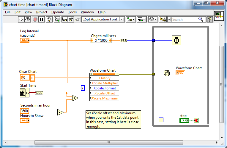
If you know the start time and the sampling interval so you can have the picture of the value of the axis of time for you.
The value of the graph axis X hour Relative. Don't forget to set the length of the graphic story to be long enough to display all the samples you want to display.
See the attached example. Here's the diagram:
Steve
-
Problem in ANSI C for example - error TDMS-ContAcq-IntClk 200877
Hello
I tried the examples in the 'ANSI C examples' folder and ran into a snag with the example in:
"" \DAQmx ANSI C\Analog In\Measure Voltage\Acq TDMS-Cont-Int Clk".
When I run it as it is, I get the following error:
DAQmx error: requested each interval of N samples event is not supported for the given the mechanism of transfer of data and the buffer size. To keep the DMA or USB in bulk as the data transfer mechanism, change the size of the buffer or the interval of event Every N samples so the size of the buffer is a multipleof even interval event Every N samples. To keep the same each event interval of N samples and the size of the buffer, modify the mechanism for transfer of data interruptions if taken in charge. Property: DAQmx_Every N samples CQI event IntervalRequested value buffer: size 1000Buffer: 12288Task name: _unnamedTask<0>State :-200877End of the program Code, press the Enter key to exit
As I was typing this, I did a quick test. I tried to comment this line in the code:
/ / * / / PDM DAQmx Configure Code / * / DAQmxErrChk (DAQmxConfigureLogging(taskHandle,"C:\\example.tdms",DAQmx_Val_LogAndRead,"GroupName",DAQmx_Val_OpenOrCreate));)
and it worked, as I suspected.
My gut feeling is that the DAQmxConfigureLogging function expects a block of 12 288 bytes, and in the rest of the code, the number of samples is set to 1000, with a sampling frequency of 10000.
In any case, I fixed it by changing from 1000 to 1024 (1024 because * 12 = 12288) anywhere in the code, so solve the original problem.
I don't have a few new questions now:
1. is this an error in the example, or am I missing something?
2. How do you change the default size 12288 DAQmxConfigureLogging() waiting for let say 5000?
Thank you.
Hall
Hey Bob,
In fact, it is a bug with this example. It comes with the value 1000 for the wrong sampling interval since it is an example of logging. When logging is enabled on a task, default buffer sizes are slightly different from the default values without connecting. This is because the default buffer sizes are powers of 10, while hard drives prefer to powers of 2. It is a maneuver of performance as we listen to disc directly from the buffer DAQmx.
I think you should be able to use 1024 as your sampling instead of 1000 interval in this example. In this example, the default value will change so that it is not immediately error (Corrective Action Request #177199).
Maybe you are looking for
-
When you add an appointment on the calendar to iPhone, there is an option for a 2nd alarm. I don't see this in iCal on Mac. Any ideas how to activate it?
-
I activated the simplified Chinese - Pinyin keyboard in settings. Confirmation of the space is activated; Fuzzy pinyin is off. In the text editor (Textilus) I switch to the Chinese keyboard. A bunch of hanzi appear in the suggestion, but I haven't ty
-
Remove E-mail twice from the trash.
When I select an e-mail message in the trash and press DELETE it disappears for a second, and then the e-mail file reappears. I have to type DELETE a second time for e-mail should in fact be deleted. This only happens in the trash folder. It did not
-
ترقية ios ايلى الاصدار الاحدث 9.2
-
Atrix phone keyboard not working not during calls
I looked everywhere for a solution to this problem and wonder if anyone knows the sameproblem. During a call, when asked to enter my phone number, access code, etc., the keyboard disappears whenever I try to press any key. When I get a button to pres