simple DMA FIFO reading two analog channels
Hello
I have a question on a method of data transfer between two analog inputs for a simple DMA FIFO in FPGA. The code is described here: http://decibel.ni.com/content/docs/DOC-6303. If I use this method, and I got out in a graph of my host VI, the calendar in the graph reflects the same schedule as the signals that have been entered? Or will they be phase shift between two signals?
Thank you
Grant
Grant:
Because it is not all information of timing with the signals in the FIFO, there will be no lag phase on the chart.
Hope that helps. I would like to know if I forgot something, or who does not explain very well.
Thank you!
Tags: NI Software
Similar Questions
-
Read DMA FIFO: reads + deletes?
Just to double check:
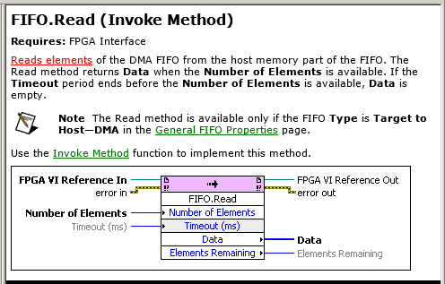
An invoke for read DMA FIFO method: reads and deletes the oldest elements of the FPGA FIFO?
I mean that it removes after reading? Porbaly deletes.
It is not mentioned in the documentation of expelicitly:
Yes, reading is destructive (meaning that it removes the element of the FIFO).
-
Using TWO DMA FIFO target host
Hi, I use a unit 9004 cRIO for the purpose of data acquisition. I try to get signals analog (NI 9221) and CAN (NI 9853) modules and transfer them from the fpga VI VI in real time using DMA FIFO, that is to say, target to the host. I thought I should use 2 DMA FIFO, one for analog and CAN signals. When I tried to put them, I put the two FIFO in the same loop. I don't know if that's the only reason, but it would generate overflow error 50400. When I removed a FIFO and put the single FIFO, it worked fine. So, I thought they must perform independent while loops and implemented two while loops that would be run in parallel. And it worked. I don't know if this is how it is supposed to work? Is this that FIFO DMA should be run in parallel loops? Are they written in such a way that the FIFO function cannot be called for more of an instance in the same loop? This seems odd.
I should also mention that I reconnected it the wires on analog, digital and CAN modules before putting them in separate loops. And I know for a fact that the FIFO CAN show underflow error if the entry of the threads on the port CAN are not connected. Also, I don't use mode Scan Engine (I think that its not available in 9004)
You are right about the 9004 and Scan Engine - or the lack of support, I say... Regarding the error of underflow, this behavior is expected when you have two Scriptures DMA FIFO the same loop. What is happeing, it is that the two FIFOs write in true parallel. Thus, when you write to FIFO1, FIFO2 expected FIFO1 finish. Then, when you write to FIFO2, FIFO 1 must wait on FIFO2 and the while loop to reiterate before he can write more data. So, on your VI in real time, if you try to access one of these FIFO that has no data in there because it is waiting to write the next block of data, then an overflow error will happen.
When you separate the two FIFOs, both can run independently from each other and write at a much faster pace. In this way, your FIFO reads on the realtime VI will not be stuck in a State of negative overflow where a FIFO is waiting for data queued.
I hope this helps!
-
DAQ write + read analog channels
Hello
I need urgent help to solve a simple problem:
My job is to write an analogue channel to a data acquisition device, then read two analogue channels of the device.
It must be made at the rate of 5 KHz.
For the smaller rate I can do using normal loops (or timed loops). But I don't know how to make using the DAQ features.
Please give me an example.
I found something but I don't know if it can be used in this way (see attachment)
Thank you!
-
DMA FIFO of FPGA to host RT is full
I transfer data via DMA FIFO of FPGA to host RT.
DMA FIFO is full, I have tried everything I know:
-increases the size of the FIFO DMA up sideways FPGA
-set the depth of the FIFO DMA to 100000000
-increases the amount of DMA FIFO reading in each iteration of the loop
-use a timed with a frequency of 1 MHz, instead of a normal life all loop
Please find attached my project folder, FPGA code and code RT.
I solved my problem.
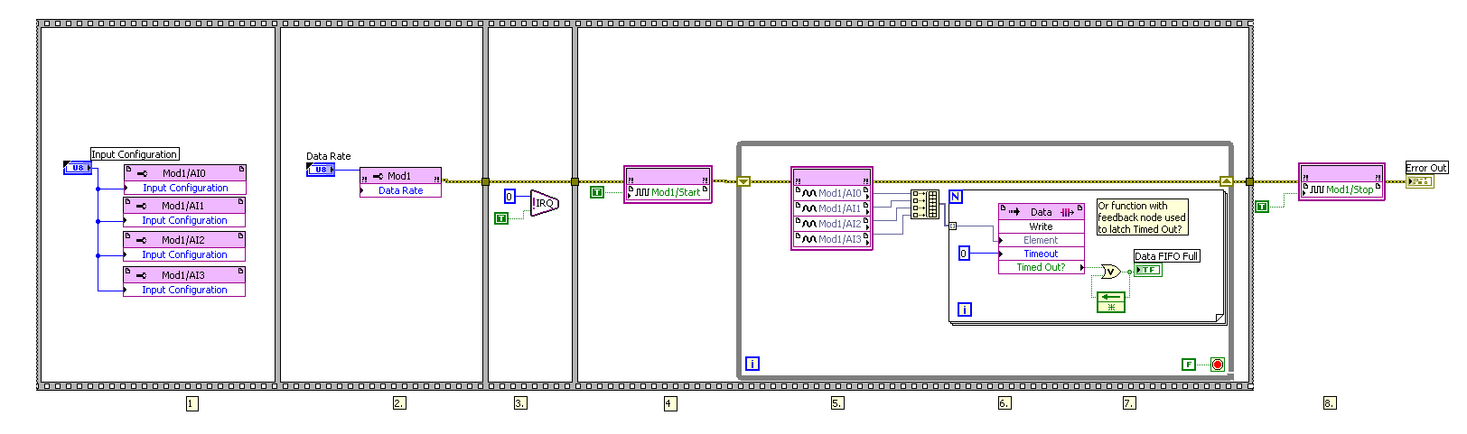
Below you will find my FPGA code before solving the problem and after resolution of the problem.
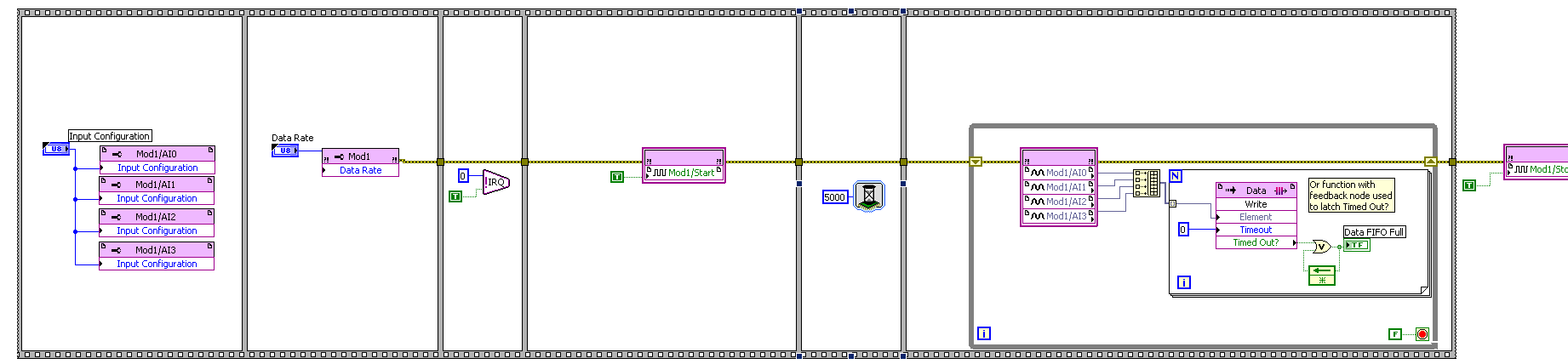
Solution: I just added a function of 5000 milliseconds (5 seconds) to wait before getting the analog input nodes samples (AI).
Before:
After:
-
Storage of samples of several analog channels (life-long)
I use a USB6356 to read 5 analog channels (more digital input port A)) simultaneously until you press a stop button. The idea is to represent all the signals captured on a temporal scale after the acquisition.
I am convert and storage of the 2D array that is captured in each iteration of the loop in another 2D array in order to have an output of 5 table lines (one for each input signal).
However, Labview can not handle so much treatment in so short a time table (I think that the main bottleneck is the 2D Transpose VI table) and accidents very soon (I have to kill the entire process and restart Labview). Is there a better way to do this?
See you soon
Your problem is that you have horrible memory management here. Whenever you add in the table, more memory is allocated, then the table is copied. You are basically out of memory.
1. use samples of N, N channels, 1 table D of waveforms for your Read DAQmx
2. change your chart to a chart and move it to be inside the loop. Maintain chart, a story, so you can still see the X last samples on it (1024 by default).
3. save your data in a file. I recommend using the DAQmx configure connection before starting the task. This allows the stream directly to a TDMS file for further processing.
-
How to read 4 similar channels at the same time with the MCC
Hello
with the mcc libraries and a card PCi-6034 classic (by calculation of the measure), I want to read 4 analog channels at the same time. I have a "scope" with 4 channels. How to read 4 channels at the same time with the mcc?
MF
Hello MF.
Thank you for using OR support. I guess you try to program in LabVIEW. Where exactly did you get the MCC library of?
-
SMU FlexRIO DMA FIFO host read the FIFO overflows broadband bandwidth/DMA issues
I'm working on an application that uses 2 modules FlexRIO, and 2 LVDS digital I/O adapters. I'm driving each of the SDC A/SDC B ports on LVDS 16-bit data at 50 MHz adapters. The FlexRIOs are expected to receive the data and write down them on four targets-to-host DMA FIFO (one per connector SDC), or two by FlexRIO. The host reads the FIFO and brings together a series of tables each FIFO output 2D. Ultimately, the individual tables (we're each a quarter of single image) will be assembled in simple images, but I haven't gotten that far yet.
The duty cycle for the data is about 80% (in other words, I'm only transmit data to the FlexRIOs 80% of the time, the rest of the time the transmitters are disabled), so the flow is about 80 Mbytes/sec/port total invasion, or 320 MB/s on the four FIFOs DMA. I find that the acquired data gaps sometimes inside that line up along the length of the material part of the DMA FIFO in FlexRIO modules. In other words, if my memory FIFO DMA are set to 65535 length, I'll see a break in the data acquired at the word of data 65536th. Data is a waveform of sight, which is essentially just a counter, so it's easy to see the break in the model. For the words of first 65535, adjoins the data, then from Word 65536 model is discontinuous and starts counting again from there, contiguously. At the beginning of the acquisition, the FIFO is erased: the beginning data read from the FIFO is always aligned correctly, so I know that the process starts at a good point.
The error is not always the case: sometimes I get continuous data through the point 65536. In addition, the error occurs independently between the four FIFO: on a particular race, a FIFO could have data of interest and some bad. Rarely, all four FIFOs have good data.
The fact that the gap of the configuration is to the point even the depth of the FIFO DMA tells me that fills the FlexRIO FIFO, the FPGA hardware without the system managing to move to read, which means that the data gets dropped during the period that the FIFO is full. Then transfer to the host comes into action, there again is the space in the FIFO, and the data is once more contiguous in FIFO memory for a large amount of data (I have not yet tried to locate a second gap in the data of a single acquisition). It seems therefore that the host doesn't have enough bandwidth between the FlexRIOs and the host of RAM to prevent the filling FIFO, or comes along some software process on the host that is temporarily stop the ability to instantly transfer.
Are at - it a specification for the SMU flow system that would indicate that we are trying to use too much bandwidth? Or are there priority controls on DMA FIFO that would allow us to raise the priority of the FIFO transfers as they are guaranteed to go in preference to other system tasks?
System Specs:
SMU-1075 chassis
SMU-8135 CPU
2 SMU-7962R FlexRIO modules
2 digital i/o modules of NOR-6585
LabView 2012 32-bit SP1 version 12.0.1
A suggestion of an applications engineer of NOR and some experimentation has solved the problem. It turns out that I was calling the method FIFO of DMA stop just before the outbreak of the transmission of the data via a control for the FPGA FPGA VI. I did this in order to clear the FIFO before you begin data acquisition, but I didn't know that this method disables also transfer data between the memory FlexRIO and host. Following this call, I trigger the FPGA code to start filling its FIFO and then begin reading. Calling the Read of FIFO of DMA apparently light up the transfer back, but it seems that the host VI has been randomly slow down enough to move to the bed such as filling the side FlexRIO FIFO and dat would be lost. I changed the host VI to insert a FIFO method call start before the trigger for the FPGA signal, and the problem is now gone.
-
Release NiFPGA 7842 DMA FIFO after reading memory
Hello
I use the card RIO de Ni7842. I've implemented a block for the acquisition of data on my FPGA (target device) and filling a FIFO to transfer the data from the target to the host machine. I've implemented the FIFO to a size of 10 k. The number of samples that I'm gaining is 16 K on three channels simultaneously.
I read the data from the FIFO DMA implemented on a host machine with the support of the C API for the Council. I have setup the FIFO for read in three steps by launching calls to methods:
-ConfigureFIFO - configure FIFO depth
-FIFO reading - read items in a host DMA - it runs in a loop playback of 1 k datapoints at each iteration (the data type I16's not 2kb which is playing)
-Stop the FIFO
What is the memory allocated on the host DMA by calling method configureFIFO need to be released explicitly by calling ReleaseFIFO? Note that AcquireFIFO is not called here.
Please advice.
Thank you!
In my view, all memory is allocated out during the call to NiFpga_Finalize, but I was not able to find a specific documentation to confirm that.
There is a specific example of FIFO included with the C API of FPGA that my be of interest to you if you have already looked at him.
-
How to use DAQmx Read to measure several analog channels
I have two analog inputs using USB 6221 and I want to measure the voltage of each of them. I use vi DAQmx-read and I select input analog, 1 sample, several channels, but I do not know how to connect several channels at the entrance of the physical channel.
Hello, Bernadette.
For reference - I would recommend ad DAQmx questions here:
NEITHER Forums: Multifunction Data Acquisition
http://forums.NI.com/T5/Multifunction-DAQ/BD-p/250
There are several ways to add multiple channels for a fast task-ni.com look for "select multiple channels DAQmx" gives me this like the hit albums:
2X8D7F5Z knowledge base: How can I select more than one channel of NOR-DAQmx LabVIEW?
http://digital.NI.com/public.nsf/allkb/A3A05920BF915F1486256D210069BE49
Hope that helps!
-
I can read two-channel USB-6008 using THE Signal Express?
Hello world!!
Is possible to read the two analog inputs at the same time?
Example: Using Signal Express, I need to read the (channel 0) analog input and analog input (channel 1) at the same time.
I try this but, the signal on purpose gives me an error message saying that I can't read several channels at the same time using the USB-6008.
Is this true?
Thank you
Ivo João
André,
Grato definition of pela.
SUA ajuda muito util faith.
SDS,
Ivo João
-
Number of DMA FIFO of items to read mismatch in the FPGA and RT
Hi all
I use myRIO, LV14 to run my application.
Request: I have to continuously acquire data via FPGA and host RT process once every 2000 samples are taken. I use DMA FIFO (size 8191) to acquire data, use timeout property in the FPGA to eliminate the buffer overflow. I had followed cRIOdevguide to implement this part. An excerpt of what I put in place is attached. All code runs in the SCTL at 50 MHz.
Question: Two or three times I met with this strange behavior, the FPGA FIFO gives continous timeout and the RT is unable to read the FIFO. The number of elements to set the property in the FPGA VI gives 0 showing that FIFO is full and no more can be written, but the RT, remaining items gives 0, so it is reading 0 (none) elements.
Solution: I put a case where I'll write to FIFO (under the code) and if the number of elements to write is different from zero. It seems to work fine, from now.
What confuses me, is that my FPGA VI said that FIFO is full (number of items to write 0 = FIFO) and gives a timeout error, but RT VI said that number of items remaining in the FIFO is 0 and therefore no data is read. No idea why this is so? My RT and FPGA VIs continues to run, but with no gains or to read data.
A few minutes after you run the code, I've seen this behavior. No idea why this happens? I try to reproduce the behavior, and will update if I meet with her again. Sorry, I can't post my code here, but I guess the code snippets to explain some extend.
Thank you
Arya
Edit: Even with the mentioned workaround solution, the problem persists, now that the FPGA written any of FIFO. And the RT VI is not able to read all the elements he sees 0 items in the FIFO. The FIFO continues to be in a State of timeout. So I guess that the problem is on the side of RT.
Why it looks like you read from the FIFO even in two different places in the same VI, at the same time? If the lower reading throws the FIFO, it will never trigger the reset, which could lead to the situation you describe, I think (it's hard to tell from a few screenshots).
Also, your logic seems too complicated. I immediately noticed that there is no reason to select the entry, the output of = 0 - simply use the 'equal to zero' output directly. On the side of FPGA, why you need check the number of items that you want to write? There's nothing wrong with writing in a FIFO that is already full. just the data won't get written.
-
Two DMA FIFO fill and asynchronous playback?
Hello
I work lately on the Labview for my system which includes the acquisition of data from two sensors in FPGA vi and communicate to RT vi, where I treat the two sensor data and subtract. I am facing a problem of synchronization. I tried 4 data points, 2 of each sensor to each 25th microsec. Here I attach a pseudo-code that is just one of my original code that shows the same problem.
When we run the code, acquire US 4 data points each 25 microsecs in the FPGA vi and storing in the fifo DMA 2.
Then, I read this in RT vi and display them.
When I have a single loop in the FPGA and RT vi. the number of elements left in the two fifo should be identical, I perceive.
But in this case, it is not. Please enlighten me why?
Concerning

Intaris is right. How work DMA FIFO is that they fill a small pad on the FPGA, and when this buffer is almost full, the data is copied (automatically and at the bottom) of a larger buffer in the memory of the host. The remaining items is the amount of data is left in the buffer of the host. The automatic copy of the FPGA to the host will happen precisely at the same time to the two FIFOs, so you will get different amounts of data in each. The total number of items (between the pads FPGA and host) should be the same, although there is no way to see that, except for read all data (until the two buffers are empty) and confirm that the total number of items of reading was the same.
-
Reading of the zeros of a DMA FIFO empty
Hello
I'm having a problem using the DMA FIFO to communicate between my real-time system and my FPGA. I use two DMA FIFO, one-way to the FPGA of the RT system and then vice versa. I can successfully get data to and from each system; However, before, after and sometimes inbetween my data, I'll get a seemingly random assortment of zeros. In the latest version of my code (which I have provided) I read the number of items stored in the DMA FIFO and read only this number to my RT system to try to get the data that I want and no zeros, but this does not work either.
I'm new to both in real-time and FPGA and so it certainly feels like I'm missing something very basic. I tried dealing with this problem by myself well and have had absolutely no success and would appreciate any help.
My equipment includes:
A Dell laptop (used as a host of the user interface)
1082 chassis
Controller of 8133 (running the LabView RT operating system)
7965R FPGA
5781 module for FPGA (not currently in use)LabView 2014 SP1
On the side of RT, you need to use a structure of the case so that you have not read of the FIFO if no data is available.
I would also like to change the flow of network to be inside of your time in a loop until the user interface capturing each data point, as it comes (connect before the loop, close after the loop and write it as the data come from the inside of the loop). This will save memory (which is VERY important in a RT system) since you don't have to set up the table.
You write only as an element in the FPGA. So any sous-suite readings should give you an array of 0 s, causing 0s back upward. You must maintain the Timed Out in the FPGA so that the data will only until to the RT when there is real data to send. Your FPGA code could be reduced to this:

-
What would be the effect of the adjustment of the depth of DMA FIFO before every read?
I'm using a PXI-7813R FPGA board using a 3rd party API. I had a few problems during playback. I looked in their API (LabVIEW) code and realized that they were in DMA FIFO depth before each reading of the FIFO. This apparently does not cause a failure of catastrphic issues I have observed are only transitional in nature.
What kind of problems, if everything can these operations cause or will be ignored because the FIFO is already running?
Thank you...
mgerceker,
According to the help file , that should be OK to do even though I could see it being a problem if it is not set correctly before performing an operation. What kind of symptoms do you observe?
Greetings from Austin,
Maybe you are looking for
-
The update does not load, and I can't "remove" program to my computer and reload as the same (needs to restart to complete the installation) error message keeps appearing even after several reboots.
-
I want to buy a new graphics card. But I don't know if my motherboard or power supply could support. If someone could tell me if my computer can support? My computer is HP Pavilion a6098d. Link: http://h10025.www1.hp.com/ewfrf/wc/product?product=3379
-
HP envy 23 all-in-one: enter the password administrator or power on password
I have a HP ENVY 23 all-in-one series [personal information deleted] When I turn on show me on the screen "ENTER THE POWER ON PASSWORD" CAN YOU GIVE ME THE PASSWORD TO THA
-
How to fix the Ox800CO133 error that blocks emails in OE?
-
Window movie maker direct, mounting split question.
Hey all,. Ive just started using wmml edited my home movies. The issue im having is after cutting my video to change the cut portion of the video will not play after ive downloaded. After Ive upload the video to my pc and play to watch in the media p