Start trigger M Series C++
Hi, I seem to have discovered a bug in my C++ when I tried to delete some maps:
I usually synchronize each task to a task and THE task is linked to the NISYNC_VAL_PXITRIG0 using DAQmxCfgDigEdgeStartTrig
Now it worked well as my main task was a S series, but when I was doing my Masters M and acquiring signals series, tasks they never start.
And Yes, I did some tests on the S series (bind it to a NISYNC_VAL_PXITRIG1 watch it freeze... to make sure that it was indeed listening to the trigger signal)
Also, if I remove the beginning of NISYNC_VAL_PXITRIG0 relaxation, it works like a charm...
Finally, each task is linked to the task of master by his "/ AI/StartTrigger ' and it works very well...
NISYNC_VAL_PXITRIG0 so only is a question... is it because some locations receive the signal sent by the PXI_Trigger or something?
Should I use the STAR version instead? (With the help of a calendar in slot 2 card)
Well after trying this Sunday...
I noticed that all my problems were gone, if instead of linking manually to trigger lines I'd let the frame automatically link as follows:
(code not real but rather a sketch)
StartTrigger (taskHandle, "" / Dev1/StartTrigger "")
and all things HR, I used, I also changed forever the call the trigger lines myself... He solkved that emit a
Sorry for the long time between response... never got the message that I got a response ^^;
Thanks if
Tags: NI Hardware
Similar Questions
-
Restart waveform immediately start trigger
I create a waveform 50 ms with an SMU-5451 in SMU-1078 chassis with a controller of SMU-8840 running Labview RT. The waveform is currently triggered by a pulse of a counter of data acquisition because the timing of the wave must be closely synchronized with data on the acquisition of data collection. However, this approach is problematic because it is difficult to produce a continuous of the 5451 signal when it is triggered in this way. If the waveform is exactly 50 ms long, will miss the start trigger. I can tolerate losing at the end of the wave, but I can't tolerate having a gap in the output, and I need the waveform to start exactly on the edge of outbreak of 50 ms. I can configure the 5451 to accept a trigger start and restart the wave immediately rather than wait for the current iteration of the waveform to complete?
I guess I could use a complete the 5451 event to trigger the acquisition of data instead, but I guess there is a way for me to do what I want.
Are you familiar with the mode "script"? You might be able to use this example script:
script restartWhenTriggeredScript

  Repeat forever

    generate wfm

    break on scriptTrigger0

      Repeat forever

        generate wfm

      end repeat

    end break

  end repeat

end of script
Basically, the idea is that, when it receives a trigger, it stops the execution of the inner loop and finish the iteration of the outer loop. Then it will start again from the beginning and to the inner loop.
Please let us know if that fixes the problem.
-
analog output digital start trigger the api c
Hi, I'm trying to start analogue output based on a digital trigger (either PFIO or a PXI line) I can make this easy in LabVIEW. However with the C API (through the Python wrappers), the problem is when I call DAQmxBaseWriteAnalogF64, writing will always be timeout that the acquisition was not triggered. However, I can't call it after the trigger occurs, because obviously, it will be too late.
I can't find any examples of C API where the analog output is triggered a digital triggering. I can find for the analog input, but is fundamentally different that you can CONV read anytime after the trigger occurs.
Python code as follows (functions are equivalent ot C API, even if you have no need of ot pass the task handle such that it maintained as part of the Task object)
# create analog output task
analog_output = Task()
analog_output.CreateAOVoltageChan("Dev1/ao0","",-10.0,10.0, DAQmx_Val_Volts, None)
analog_output.CfgSampClkTiming("",outputRate, DAQmx_Val_Rising, DAQmx_Val_FiniteSamps, numSamples)
analog_output.CfgDigEdgeStartTrig("/Dev1/PFI0", DAQmx_Val_Rising)
analog_output.StartTask()
analog_output.WriteAnalogF64(numSampsPerChan=numSamples, autoStart=False,timeout=1.0, dataLayout=DAQmx_Val_GroupByChannel, writeArray=data, reserved=None, sampsPerChanWritten=byref(samplesWritten))print("Analog output: Wrote %d samples" % samplesWritten.value)# create digital trigger dig_out = Task()dig_out.CreateDOChan("Dev1/port0", "", DAQmx_Val_ChanForAllLines)

# create digital trigger function
highSamples = 1000
numpts = 3 * highSamples
doData = np.zeros((numpts,), dtype=np.uint32)
doData[highSamples:2*highSamples] =  2**32 - 1

# send digital trigger
doSamplesWritten = c_int32()
dig_out.WriteDigitalU32(numSampsPerChan=numpts, autoStart=True, timeout=1.0, dataLayout=DAQmx_Val_GroupByChannel, writeArray=doData, reserved=None, sampsPerChanWritten=byref(doSamplesWritten))
print("Digital output: Wrote %d samples" % doSamplesWritten.value)
Hi PatrickR,
You can review examples of code NI-DAQmx (ANSI C) text based on the production of an output using a trigger to start digital analog. If you included/checked support textual dusing your NI DAQmx driver installation, you can navigate to Windows start > all programs > National Instruments > NI DAQ > Teaxt-Based Code support > ANSI C examples > analog output > generate voltage > Mult Volt updates-Int Clk - Dig start. If you have questions/doubts about the material.
-
PCI-6221 PFI0 start trigger is stray signals reading
We have a card PCI-6221 attached to a SCB-68 in a control console, we've made dozens of times. However, this time, we will have problems with the beginning of PFI0 relaxation. Operation of the actuators 24 v remote (cable to DAQ card but operated through manual switches) triggers the beginning. We tried a shielded cable and everything is grounded. There is no parasitic voltage coming into the SCB-68 box. We sent also all the other analog I/o box. It's just the son of trigger start going. What is unusual, is that if we give a thread to the PFI0 (Terminal 11) who does not finish anywhere, we just hold in the air, do not cross any other thread, running our actuator valves still initiates the trigger. If we remove the wire, it does not raise. It's almost as if she receives wireless signals. But how wireless receives + 5V to trigger I don't understand. We also tried to use a spare PCI-6221, same known issue work. When you view the PFI0 in MAX, flipping the switch actuator will cause the counter generate 400 + charges. A normal release with our power switch usually generate 10-20-count indictment. We are really puzzled. Thanks for any help!
Don't have not an answer to the first question, will have to research.
THA Cabinet is wired the same, the only difference is that we added a transformer so that the system can run on the seas, but has not actually been hooked again, sitting in the Cabinet.
Yes, we used a cable leading to one end. We tried the ground at both ends, the same results. I also waved to the cable in the air and a people in the head with it, it made me feel better.
Don't think on the unused entries in the Earth. Personally, I think that the PFI0 is to be triggered with less than the + 5V, the scope is the very low voltage reading.
But I found a solution. I mentioned in the original post that trigger actuator, just once, causing 400 + edge detections/counts when viewing in MAX. It is a large number of charges in such a short time. So I programmed in a digital filter using a min pulse width. ".". 00256. Eliminating the 400 + short bursts of any signal. I used the example of filtering VI in this knowledge base article:
For those who have similar problems, there is no physical change, just incorperate of wiring of the filter.
-
I am a user of first of the NI USB-6361. I'm programming in .NET (c#) and using the NationalInstruments.DAQmx class.
What I try to do is the following:
Using a digital output port, generate a wave from 0 and count up to 31 and then stop with a power of 0. Each count is 12.5 microseconds long. This wave must be generated 15 times, once all the 1 millisecond. i.e. 15 waves to 15 milliseconds
While this is happening, I want to taste a milliseconds of being digital to analog input 10 from the front of the output wave. To do this, I intend to sample the analog input to 2 MHz.
I think I can manage the entry next analog examples. It is the digital out which I am having trouble with.
I can see that if I created a table of 80 (1000 microseconds / 12.5 microseconds) values, beginning with 0, from 31 and the remaining values, the value 0. Then, I use this all the time with a clock of 80 kHz wave form.
I want to know is if there is a more simple or more elegant solution. that is, if I wanted to easily vary the maximum number allowed (from 31) value or the number of waveforms must be generated (from 15).
For example, can I use a redeclenchables to start a waveform finished?
Or could I get rid of my wave form all together and use a counter?
I don't know if these (or other) solutions would be appropriate, and how to put them in place. I have some difficulty finding appropriate c# examples.
Any help would be greatly appreciated.
Ah ok...
If you think that this approach a bit more intuitive:
Configure a continuous (or finished if you want to only repeat a number of times model) output of the frequency meter task want to knit the digital output.
Instead of buffering the digital output with 0 task, to the end of the buffer with the 32 stamples (or however much you want to generate). Configuration of the task to be "finite" and the number of samples that is equal to the number in your buffer (for example, 32). Set up a trigger digital task start and use the meter's internal output the command source. Set the trigger to be redeclenchables.
Set the analog task was over and a length that interests you. Configure the trigger to start the same that you have made to the task of digital output (including making them redeclenchables). You can set the time between trigger start property to allow to enter your task to wait that long after the beginning of the output to start sequence to acquire.
You can run the continuous analog input (using 0 as a buffer in your task of digital output as well) and avoid having to use the meter. To make this work you have to synchronize the start of the tasks together (e.g. use the beginning of AI trigger to trigger the task of digital output) and then follow the number of samples on the enter task in order to know where the timing windows are that you are interested. The calendar will not derive as each task derives its clock to the same time base (just be sure that you have selected the output rates that are divisors of 100 MHz).
Best regards
-
I created a program that reads analog data and draw a waveform, but I need to stop the program when the voltage drops to a certain tension. When I tried the analog edge trigger it showed the error in the subject:
Reason: The requested value is not supported for this property value. The value of the property may be invalid because it is in conflict with another property.
Property: Trig startup type
Requested value: analog edge
You can select: Digital Edge, no
I understand what the analog trigger is not available for my DAQmx version, without again getting equiptment, can I use a trigger to stop reading data at a specific voltage?
How to start and stop a similar read digital triggering?
Thanks in advance!
Ah! Well, then the Boolean value of status would be connected to the State of the thread of the unbundled error, Boolean stop to the stop button and the Boolean value to the right would be the stop for loop itself... so something like this (see image). This is an excerpt from LabVIEW 2014, so it can not easily fall in your version, but I hope it's clear enough on how you can wire it to the top.
-
Producer consumer Start Trigger
Short explanation: I use a party apparatus 3rd signal a TTL to use as my trigger early in my VI. My cDAQ and modules seem to have the ability to send a trigger start regardless, but I could not track down the how to do this in a system of producer/consumer. I have an idea at the bottom of the long explanation.
Long explanation:
I am running a test system that monitors the pressure wave by an inflammation of the hydrogen/oxygen. The components are a cDAQ-9188 with modules 9222 (x 3 HAVE broadband), 9481 (x 2 relays), 9402 (x 1 i/o Module), 9221 ('Low' speed HERE).
Based on the recommendations contained in this forum, I placed my DAQ in a producer/consumer architecture.
At this point the system works for the most part, I still have some more things to add for all the information I want to collect. However, it records at high speed and the 9221 and the 9222 modules are synchronized. He collected reliable data to date successfully.
When the system boots it will follow, but not save. I need to fill the structure tested with gas at a specific concentration before I switch on/registration. When I press the record button I have a TTL of the 9402 signal to my high-speed camera and I close a relay on a 9481 who engages in an ignition system. Ignition system takes a variable amount of time to load and shoot so I have a timer that leaves the TTL and the active relay for half a second.
My problem and it is a small, comes up with the system monitoring and synchronization. In order to get the system to synchronize properly, I had to generate an external impulse in PFI0 to use as a trigger. I tried to assign the different clocks available as a trigger of the beginning, but I found myself with unsynchronized data.
Is there a way to generate a pulse on my 9402 to use as a trigger? It feels stupid for me to use an external device, when I have something that can generate the signal that I need.
Thinking about this post, I have solved my problem, at least in my head. I think I can move the output TTL VI (that I'll eventually change to DAQmx) in the loop of producer and move my statements true or false for the consumer in the form of a 1 d array loop in my queue to start recording. Probably more than that, but I can only learn by experimentation on the right?
Thoughts? Recommendations?
VI attached.
You cannot generate a pulse with the 9402 himself. The pulse would be actually generated by the 9188. You must create a task of meter output to generate a pulse train. Try the attached example as a starting point to experiment with the meter.
This Vi is for LabVIEW 2013, if you have an older version let me know and I'll try to convert.
-
Is not start a new series of SSD Intel 520 180 GB replaced on ENVY Notebook (i7 3632QM) WINNING 8 m4
I have a couple of this desire m4 I7 product: C2M81UA #ABA who have 1 TB blue WD scorpio Win 8 Preinstaled.
It is up to date with the latest form of HP, Intel and Microsoft updates. Including fast storage to intel.
Recovery operating system, applications and drivers DVD set has been created using HP recovery utility.
After that, HD has been replaced with SSD Intel 520 Series 180 GB.
Issue.
SSD is not start after the installation of the OS was made using the HP installation DVD set.
Remarks:
The SSD is recognized, while holding, partitioned and Windows is correctly installed
However it does not start it freezes after Hp logo without message when Win 8 should begin.
Changing legacy BIOS boot and secureboot options results in error message appear "3F0 there is no boot device."
even if a new fresh installation by using any combination of these options, the SSD is recognized and the tests went ok in the bios utility.Linking the SSD as external USB installation interrupted Windows can be seen.
He tried with an another SSD, which is the same model with the same results.Compatibility was previously at the website of intel for this mobile chipset QM77 http://www.intel.com/content/www/us/en/chipsets/performance-chipsets/mobile-chipset-qm77.html
and SSD http://www.intel.com/content/www/us/en/solid-state-drives/ssd-520-brief.html
In my opinion, it may be an option of configuration of the bios, firmware or the driver, but after 3 weeks I'm out of ideas.
Does anyone has an idea how to solve this problem?
Thanks in advance
Hello
He finally works!, what I just did in the last hours is to reinstall from the recovery HP DVD media. But first I set old bios to activate OS, Secureboot to disable.
Then it was installed, it worked well this time.
When I did disabled legacy BIOS os and active secureboot.
It runs as it wants!, it takes only 5 seconds to turn screen tile (I use fingerprint to log).
Thank you all for your support!
-
DAQmx start and read series vi low bits before actually reading
I use DAQmx writing to set the bit on a map of 9403. When I set a little high, then try to read this small in a vi subseqeuent little gets low! Both DAQmx Start DAQmx Read screws seem to back the lower wick. How is that supposed to happen? I was certain that bits would not be initialized weak unless the device has been reset.
I'm guessing that you create a digital output channel, call start, writing and then create as a separate digital input channel and call start-> reading or reading.
Create the input channel changes the direction of the line. This happens to commit (which you cross when they if call to start, or read with no departure). Once the changes of direction, you no longer drive line. That's why you always read zero.
You have two options. You can call read after write (in the task of digital output), or you can have fun with the tristate property. TriState is a channel DAQmx (DigitalOutput-> Tristate) property. Aid that it is good enough.
Two ways to read the value of the line without changing the current state of the row.
-
Flash player cannot start on the series of Photoshop help videos
How can I run Flash player on the help of Photoshop video series (CS5 Extended)
Refer to this:
Flash Player Help. Installation problems | Mac OS
Flash Player Help. Installation problems | Windows
Mylenium
-
CS6 InDesign does not start, gives a series of messages.
I faced a problem to launch InDesign when you open a file. Then as launch costs, it also gives the same errors.
Breaks Finally, sometimes with a message that shows that he could recover at the time where we can respond, it crashes!
The screen sequence is added here, with transliteration.
First Message:

C:\Program Files (x 86) \Adobe\Adobe InDesign
CS6\Required\GROUP. RPLN isn't is either not designed to run on window
or it contains an error. Try to install the program using the
original installation media or contact your system administrator or the
software support provider.
Second Message (after the first message OK)

Failed to load the ELEMENT of PAGE EPS. RPLN plugin. It is tributary of the
GROUP. RPLN plugin, which was not able to load. Please check
documentation for the GROUP. RPLN plugin.
Third Message (after the second message OK)

Cannot load the PDF file. RPLN plugin. It depends on the EPS PAGE
ORDER OF THE DAY. RPLN plugin, which was not able to load. Please check the documentation
For the POINT of the PAGE of EPS. RPLN plugin.
Fourth Message (after the third message OK) | When I was trying to launch of an InDesign file dirct

You want to start the ASR?
Click Yes to start the recovery.
Click No to delete the data recovery for all documents.
Click Cancel to postpone any recovery of document at the latest.
Last 'message of hope' that still crashes! Notice that both are in the same image!

Any help is appreciated! Thank you.
Expand what Peter has already said if you please, drag the folder of office recovery. Navigate to the location 'C:\Users\username\AppData\Local\Adobe\InDesign\Version 8.0\ and then drag the file en_US desktop. " Relaunch InDesign and crash test. Then reinstall if the problem persists.
-
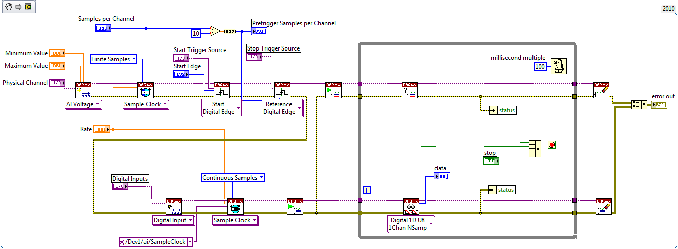
DAQmx: set up a digital acquisition continues with start and stop trigger
Hi all
I write because I can not find a solution to my problem.
As written in the title, I just want to do an continuous (continuous sampling) a digital line. The fact that it's a digital line instead of an analog is no big deal, I guess. I want to start the acquisition on a rising edge of digital trigger (PFI0 for example) and stop acquisition on a trigger too (forehead down on the same signal (PFI0 even then) or a new front amount). This way I could precisely control the time of acquisition or of the start or stop other devices.
Since this is a digital acquisition, you need to do first "something": create a fictitious analog input task and get the clock back to the digital input. I setting this analogue of the task to start on a trigger. It works but I can't find a way to stop it on another trigger.
Do u hav no idea how to implement it?
Finally I have not found an easy way to break cautiously the VI to wait for a trigger (in case you want to start an acquisition with different settings for example). Do you use the task to Abort or is it better to set a deadline to playback digital channel VI until the outbreak occurs?
Any help would be appreciated!
Thank you
Config: LV 2010, latest version Daqmx and USB card or 6251.
Hi Chris,
One way is to use counters as Kevin described. For me, it's usually easier to create the dummy task that has the timing engine (as I HAVE), but it depends on what resource you have on your board you will not need
 .
.In fact, the example is the same thing that you need to measure continues - just what you need to do is remove the counter part and replace the trigger reference to be external (your stop trigger).
with this approach, you should be able to do the continuous measurement - I noticed that you need DI - in fact with few changes you should be able to use this example. DI does not have its own timing engine, that's why you should use the external sample clock. If we use the example to create dummy HAVE to provide the sample clock, and we start DI task until we start to HAVE fake, then we can get pretty much continuous clock which begins start trigger and stop the trigger of reference.
Take a look in the change - once again, I have not tested, but logic seems to be OK.
with sincere friendships.
s9ali
-
Guys keep with me, I'm another PLCs and VB/C programmer, there are still the old paradigms of locking my head.

See attached vi. After that I disconnected the entry in the series, the wizard exits still instrument 0,0 to its terminal at regular intervals about 1 hz. Now how does the wizard output always inst 0.0 without a trigger entry series? There must be a timer somewhere... but I searched everywhere there is no timer, including by opening the front panel of the wizard of the instrument. I watch the whole bulk of the loop and block VISA etc, there is no synchronization setting.

So my question is, if there is no entry of series by using the instrument, which is the parameter object that triggers the instrument Wizard still out 0,0 at regular intervals? Where the object/setting?

Thanks in advance
Great big thank you! I can sleep tonight! Muahahahahahha!

-
How to delay a PXI-5122 trigger before routed to string of PFI
Hello world
I use a PXI-5122 in a PXI chassis. I want to synchronize with two external devices. The first will send a trigger (with a 10 Hz repetition rate) for PXI-5122. Then PXI will generate a trigger (with a constant delay) in the second.
It seems that I need to generate a trigger, then export this trigger to PFI 0 line, but I do not know how to delay triggers with a timeframe of 4µs. I read that there is a slight delay between a trigger on the PFI and the first sample. And the length of the cable is also an important factor to consider.
Could someone give me some suggestions?
Wednesday,
Thanks for the drawings, that helps a lot! Somehow, I see this work (how to set up the scanner):
1. set up the record length to be 12us (4us trigger samples, 8us after outbreak). If the sampling frequency is 100 ms/s, that would be a record length of 1200 samples.
2 configure the position of record reference to 33%. That's how the digitizer breaks 1200 400 samples according to trigger before triggers and 800 samples.
3. configuration of triggering immediate reference. This will allow the acquisition of trigger the moment she gained 400 before triggering samples.
4. export the "reference trigger (Stop)" to send to Device_2. This output pulse is of variable width, so if you want consistency, you will need to the Device_2 trigger the rising edge of the pulse, did not not fall m. Once 400-pre-trigger samples are acquired, this impulse will be sent, and then the scanner will be immediately habitable after initiation of sampling.
5 configure the trigger of the entrance of Device_1 (10 Hz trigger), as the 'Advance trigger' and 'Start Trigger'. This will make the digitizer wait this impulse to start sampling before the next record. We set up, the relaxation of beginning to the 1st record and the trigger in advance for all subsequent records.
This facility should allow a pretty decent timing, but please test to be sure that it will be sufficient for your application.
Kind regards
Nathan
-
Start-up delay triggers real beginning of the acquisition of waveform on SMU-6535?
How long does take a condition of trigger start happening to the actual start of the acquisition of waveform on an SMU-6535? In my case, it takes ~ 70ms, who seems to be too long. The delay times, I found in the manual are all down in one nano-second two-digit range.
Here's a little history: I'm trying to measure a PWM signal to report cyclic verity, generation of total time, frequency, etc.
The PWM signal is entering in the SMU-6535 on line Port3/3, and I rider Port3/Line3 to PFI5 on my map of derivation. Start trigger is configured to fire on the PFI5 front, with the acquisition of waveform happening on Port3/Line3. PFI5 and Port3/Line3 consider both the same waveform PWM, which is the yellow signal out of range.
The task is configured to use a sample of 10 Mhz clock frequency and collect samples of 2 500 000, coming at a time of acquiring signals 250ms. You can see on the scope probe that there is a gap in the PWM signal. I want to collect just the first section, and I know that the article is (or should be) long 250ms.
However, I am very clearly this gap and 70ms ~ the next wave PWM of the PXI system. PXI signals is checked 250ms. The problem is that it is delayed by ~ 70ms when the first time PFI5 goes high when it actually starts the acquisition.
Ignore the ringing. The probe is not the best reference.
Here's the installation code:
readPwmTask = new NationalInstruments.DAQmx.Task ("task of reading PWM");
readPwmTask.DIChannels.CreateChannel ("PXI1Slot6, Port3/line 3", ", ChannelLineGrouping.OneChannelForAllLines);readPwmTask.Triggers.StartTrigger.ConfigureDigitalEdgeTrigger ("/ PXI1Slot6/PFI5", DigitalEdgeStartTriggerEdge.Rising);
readPwmTask.Timing.ConfigureSampleClock ("", 10000000, SampleClockActiveEdge.Rising, SampleQuantityMode.ContinuousSamples);Reader = new DigitalSingleChannelReader (readPwmTask. Stream);
drive. SynchronizeCallbacks = true;drive. BeginReadWaveform (2500000, New AsyncCallback (DataReady), readPwmTask);
Narrowed it down.
This problem only occurs when it is the first acquisition of signals in the life of the application. If I do a 'normal' acquisition before attempting to use the departure function acquisition, it works much better.


Maybe you are looking for
-
Web pages get scrambled, just a little. So the fonts, as other elements sometimes distorted
I have read several similar problems. Still the same thing. Only none of the solutions have worked for me. Disabling hardware acceleration has changed nothing.With me, this problem started after the update of the display drivers. I have Ati ah3650. T
-
The FPGA IO corresponds to which C-series e/s?
I have a PXI-7813R with connectors 0 and 3 connected to a chassis with modules of series C in them (9474, 9205, 9206 and 9423). I want to know that I/O corresponds to what e/s on these chassis. As far as I know my FPGA project (which was written not
-
Automatically open the change step where drag and drop a steptype
Hello I would like to open (launch) Assembly step (labview module) when I drag and drop the step type. TestStand can step edt by the 'Edit' button or shortcut (Ctrl + E). Is it possible to do? I know that shortcuts are hardcoded... Thank you for your
-
No access to blocked senders list
I can't access my hotmail blocked list. It says: Windows Live Hotmail was not able to complete this application. Microsoft may contact you regarding any issue you are reporting. But then never contact. ARGH!
-
I need this product to be upgraded to windows 7 as soon as posible