superimposition of geometric matching
I use a geometric matching
but could not superimpose the exact match
is there anyway to do
This VI is located in the folder shows the example how overaly matches:
-Christophe
Tags: NI Hardware
Similar Questions
-
Extraction of geometric matching
Hello
IM wondering how I can extract the only area of the image that are in the geometric match. I want to measure the light intensity of the area of the LCD screen, but I don't want to measure the whole box, but only the area of geometric game to be precise.
As an attachment, you see I want to extract only area included within the green line.
Can someone help me?
Thank you
You will always have a table 2D of information, so you may not necessarily get rid of this "black" area However, if you have created a binary image of the threshold you could then multiply the berries together then you would end up with a table 2D with the original pixel for the 'green zone' values and then everything else would be worth 0. This should do some math you use to light intensity fairly easy to apply by ignoring the 0 values.
-
geometric matching: difference between the scores and correlation
Hi all
What is the difference between the scores and correlation in geometric correspondence?
Hello
the correlation score is based on pixel intensities while the score of the geometric game also considers the characteristics of the geometry. See the Concepts of Vision or (geometric matching-> discussion).
I hope this helps.
Best regards
K
-
creation of several geometric model
I have different models and want to create a file of multiple geometric model
I'm unable to do so.
I downloaded the models
Please help me with it
Hello
I was able to create a more geometric models from the images you attached to this post.
To create a model of multiples, you must make sure that the files you select to add to hear several geometrical models example are geometric feature corresponding to models.
To create them, before adding them to the example, use the template editor, which you can access from the Start Menu > programs > National Instruments > Vision > Editor
Select the file > new model... and then choose the option "geometric matching Template (basic functionality) in the list.
Select your template image, or image that you want to extract the model from and go through the different tabs to create the model.
Repeat for all models to add to the multiple template file.
Once they are created, you should be able to use the example to create. I worked for me.
Best regards
-Christophe
-
problem with learning several geometric pattern
Hello users of Labview,.
My goal is to load different templates located in the target folder, create one or more models then, perfom some treatment (located in another file) image.
The example provide in file vision works perfectly but if I change the path, it seems impossible to create a multiple repeat. In fact, I got the following error message:Error 1074395628 has occurred to IMAQ learn several geometric patterns
IMAQ Vision: Image model corresponding invalid geometry.
Certainly, I do not understand a part but I don't know where is my mistake.
I add to the multiple associated model, an example of template image and the image to test.
Please, can I have a help or suggestion to understand this problem.
Thanks in advance for your help,
Best regards
Hi matriax,.
Good to know it helped.
Come to your questions,
-Yes, model geometric information, or even in vision assistant also will not work.
-In my code too, it does not work. The reason is explained below.
-Yes, model created with assistatn vision should also work.
Coming to the creation of a model, there are two geometric methods correspondent-function based and based edge.
-Labview code uses geometric based function while u have created the model in edge based method.
-If you see in vision assistant, settings tab, you have the type of algorithm two options. Select the base feature and you should be able to run it and then assistant labview and vision.
For more details on geometric matching please refer to http://zone.ni.com/reference/en-XX/help/372916L-01/nivisionconcepts/geometric_matching_technique/
Hope that helps
 let me know if you have any other questions.
 -
Hello Experts!
I have a lot of problems and less time to solve alone, so I need help. My problem is this: I have a picture, and maybe he has a non-linear distortion, that this picture is made by a scanner. I would compare the scanned image and the real using, however the corresponding.
The result image is always full of light and dark defects. Of course the corresponding position however is determined by special criteria.
Is it possible to correct its distortion to the corresponding phase? Or could you suggest me some way to achieve my goal?
Thank you very much!
Hello
Unfortunately, unlike the geometric matching algorithm, the Golden template comparison algorithm does not work. To be able to use the algorithm on distorted images, or images that have been acquired in a different State, you must calibrate the two images and fix them before using the algorithm.
Christophe
-
difference between functionality and corresponding geometric base edge
Can someone help me with the difference between a function and a corresponding based edge geometric model?
I understand that:
o geometric based function corresponding directly uses the intensity of pixels and reason for research and their settings
o edge based geometric matching first calculates the gradient of the image and then uses this gradient to find features with generalized Hough transformation...
More information here: documentation OR
I hope this helps...
-
IMAQ Vision NOR find circular edge
Hello
I had a few a problem with a circular border of LabView Vision search. The problem is when the function found my circle he put a red circle, that's good! but when I move the object to try to follow the point, all the old red circle will not disaper.
After I got everything its quite messy in my interface.
I got a picture of the problem.
I want to know how to clear the circle each iteration.
Thank you
Hi PIOU123,
To clear the overlay use the clear overlay VI IMAQ. An example of this in use VI can be found by going to help > find examples and then navigate to the Modules and Toolkits > Vision > geometric matching > geometric Matching.VI
-
Hi all!
I have been using NI editor for a long time. It is a program very useful, and it can be called form WILL / VBA. That is why it is so useful. I would like to know how to use this feature or the program from my own code. (call parameterized editor e.g. my program to match pattern as in VBA form / VA - for the current Image).
I used the system run vi - running standard, but in this case, the image file *.exe files must be selected.I would like to know how can I use T.E. in my own program, as flexible as possible, GO / VBA - for the current image.
Thank you very much!!!
Hi Durnek,
As far as I understand it, you want to develop an application in LV that does Pattern Matching.
To do this, you need a model that you define in the template editor.
In delopyed applications, the templates are predefined, in which case Editor is a great tool, but didn't need to be called at every race.
Yet, we met with similar requests, and we also have a product suggestion to Board editor in LV, similar to going
We hope that this feature will be available in the future.
Until then, here is a few parameters that could be described
/ News
 ath - pm - gpm-gpm2 d
starts Publisher and opens the image located at the specified location.Settings - pm - gpm-gpm2 d are optional and allows to create a corresponding model type model, geometric matching (inheritance), geometric new correspondent and vice inspection respectively.
You can combine these parameters to create a model of the desired type. Only the specified tabs will be activated. If you don't specify any optional parameter, all tabs are available./ edit
ath
change model that is at the specified location.It is the responsibility of the user to save the model manually in the interface, since the training interface is called by the command line and has no way of the calling application whether the user OKs or cancels the editor.
An important point in what concerns the appeal of the model by using a command line: If the path contains a space, you must use quotation marks, so that the exec knows that there is only one parameter.
For example:'Path to the Editor\NI Vision template Model Editor.exe' "/ new
 : \Images\8 bit\image.tif '-pm - gpm d.
Please answer if this meets your application requirements
Best regards
Mircea
-
Research and correspondence - difference between 'Match' and 'geometric model Match "?
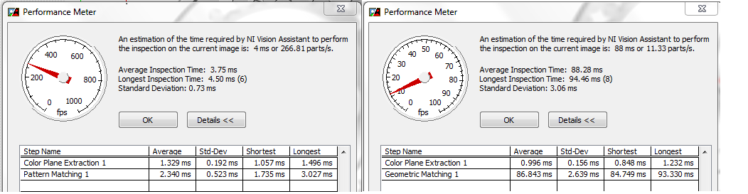
I was wondering if someone can explain to me the difference between 'Pattern Match' and 'Geometric pattern Match' screws? I don't really know how best to use for my application. I'm search/match small spherical particles in a video gray in order to follow their speed (I do that after subtracting the two following fields to get rid of background motion artifacts).
Which should I use?
Thank you!
Hi TKassis,
1. you can find from this link for the difference between these two,
Pattern match: http://zone.ni.com/reference/en-XX/help/370281P-01/imaqvision/imaq_match_pattern_3/
Geometric game: http://zone.ni.com/reference/en-XX/help/370281P-01/imaqvision/imaq_match_geometric_pattern/.
2. I always prefer the match pattern because of its speed of execution and incase of correspondence to the geometric model that it took a lot of time to match your result. You can find in the attached figure for the same image with these two run time algorithm.
-
How can I read a model and tell if it is a model of pattern match or a geometric model?
Hey all,.
I would like to know how I can read a template´s of information about whether it is a model macthing or a geometric model?
In my code, users of the models and the algorithm must match them using special or geometric criteria depending on the model.
For the moment I do by including a P or G file name, but I would avoid it and read the information in the file.
Any ideas?
Thanks in advance,
Esteban
Hey Esteban,.
You can use the VI "IMAQ is this Info 2 VI Vision" for Abboud information:
IMAQ is Vision present 2 VI Info - OR Vision 2011, using LabVIEW - National Instruments
http://zone.NI.com/reference/en-XX/help/370281P-01/imaqvision/imaq_is_vision_info_present_2/Take a look at the attached VI
Stephan
-
scale invariant geometric pattern matching error
I want to create a VI that pattern matching which is scale invariant, i.e.
If I create a model that is larger than the target image, it should be able little ot
recognize it, anything. I created a vi that is rasthaus to this post. I get a
error in saying that this model doesnot have information for corresponding invariant scale. I'm attching a snapshot of that too. Also, the weather in real time image is displayed with the model. Anyone.
-
Edge based geometric invariant scale corresponding learn property?
Hello world
I want to create a VI that pattern matching which is scale invariant, that is if I create a model that is smaller or larger, or any angle that the image of the target, he should be able to recognize, no matter what.
The question is when I go to form the model using LabVIEW VI, the dose of IMAQ Setup learn geometric model 2 VI no option on the specification of the invariant properties of SCALE or the ROTATION property. But they were as in the detection property IMAQ configuration Match geometric pattern 2 VI SCALE and ROTATION are there.
If I activate the invariant property of the detection scale it gives me that isn't a corresponding error information for invariant scale model. But I did not well in the Setup IMAQ learn geometric model 2 to specify.
These goods are in the VISION Assistant, but I want to do in LabVIEW.
Kind regards
@sk
I think in this vi you can get:
http://zone.NI.com/reference/en-XX/help/370281AA-01/imaqvision/imaq_advanced_setup_match_geometric_p... -
How can I get good results from the detection of matching/shape of reason for this image?
I need to be able to identify all nine squares in the first image (0000094718...) and others like him. I tried to detect shape, filtering and geometric pattern match. I tried to vary all parameters within these functions. I tried the image preprocessing (and the model, if any: usually created from only one of the boxes) with thresholding and/or a muliplier before using the detection or the corresponding function and I still can not get all nine boxes and only these nine boxes.
Can someone offer some help? Ideally I would be able to use the shape detection, because it returns the coordinates of the corner rectangles and those who are particularly useful to me. What confuses me about this feature, is that after setting the width/height minimum/maximum of rectangles to find, the program seems to ignore these instructions and returns matches outside these limits.
It would be even better to be able to have a script which will identify all nine boxes in two attached images. The boxes in the second image (X820A32) are more square.
Thank you
Holly
Try the attached script. I think that you use only may not be the optimal threshold values. You may find that you want to use a smoothing filter before making the threshold. This should also help with nuisance particles.
-
I have an application of machine vision, in which the geometric pattern match technique was used to find the target in the images of type variant.
as we know, we do a geometric model by model OR editor in the editor we can adjust the parameters of the curve specified settings to get the desired curves and we derive the custom box to ignore during the match. then we save the use of the same model in our application of vision.
Now my question is coming. When I program my request for the geometric game. I have specified the parameters of the curve for the entrance of the IMAQ Advanced Setup learn ringtone 2, of course, I have to adjust this identical to the model, but I don't know how we extract the geometric model. I tried all the methods, for example, I can read data custom, IMAQ get characteristics of the geometric model(it's just for the basic functionality? so is there even a VI based edge?), even at anasys PNG file formats! But I can't read the info of the geometric model by myself!
It is also illogical to adjust the CURVE SETTINGS manually again for the " IMAQ Advanced Setup Learn Pattern 2" after that I already have in the template editor OR!
Hello
Why do you need to specify the curve settings once again, if you have already built a model using the template editor? You don't need to use "IMAQ Advanced Setup learn geometric model 2 VI" to find games (see the attached example).
You can wire the 'curve settings' control to 'IMAQ configuration geometrical game model 2 VI', but the values are not used if wire you a Boolean true to the node "use learning curve settings" (it's like that by default). To prove it, I enclose a small program with pre-created model (using the template editor) for a geometrical alignment. The model and the test of three images are also included.
Try changing the settings of the curve with the 'use know curve settings' enabled, and you will see the corresponding score remains the same. Disable the Boolean control, then try to change the curve settings.
Also take a look at the detailed help for "IMAQ configuration geometrical game model 2 VI", specifically the "learning curve parameters of use."
I hope this helps.
Best regards
K

Maybe you are looking for
-
What is java enabled via Firefox to my iPad?
Safari does not allow me to activate JAVA and I can't find an app to do. JAVA is activated via Firefox to my iPad, or y at - there a patch or something else to do? And if so, how I accompolish this?
-
What is the fastest connection that I can use for a new external SSD for my MBP late 2008?
That IS the question. I want a new external SSD for my MBP late 2008. What is the fastest connection type that works?
-
Photos: 0 images, Photos library: 3.98 GB
Hello, I have a terrible time understand why [pictures > photo library] says that its size is 3.98 GB but there are 0 photos in the Photos app. I am trying to clear up some space on my laptop. How does less in order to find these "ghost" images and r
-
Pavilion dv6 1110ax motherboard replacement
Hello Recently my 1110ax BIOS corrupted and m unable to get by any way mrntioned on the forums. Key combinations don't work not and this USB STICK. Now the service center guys say that the motherboard has problem and must be replaced. which I doubt c
-
If I close my browser, I have to connect again to hotmail next time I check my emails.
I have to connect to hotmail every time This has never happened before, and it lasts for a week now. If I close my browser, I have to connect again to hotmail next time I check my emails. I see other people are asking the question, but when I click o