Synchronize the analog I/o on DAQ
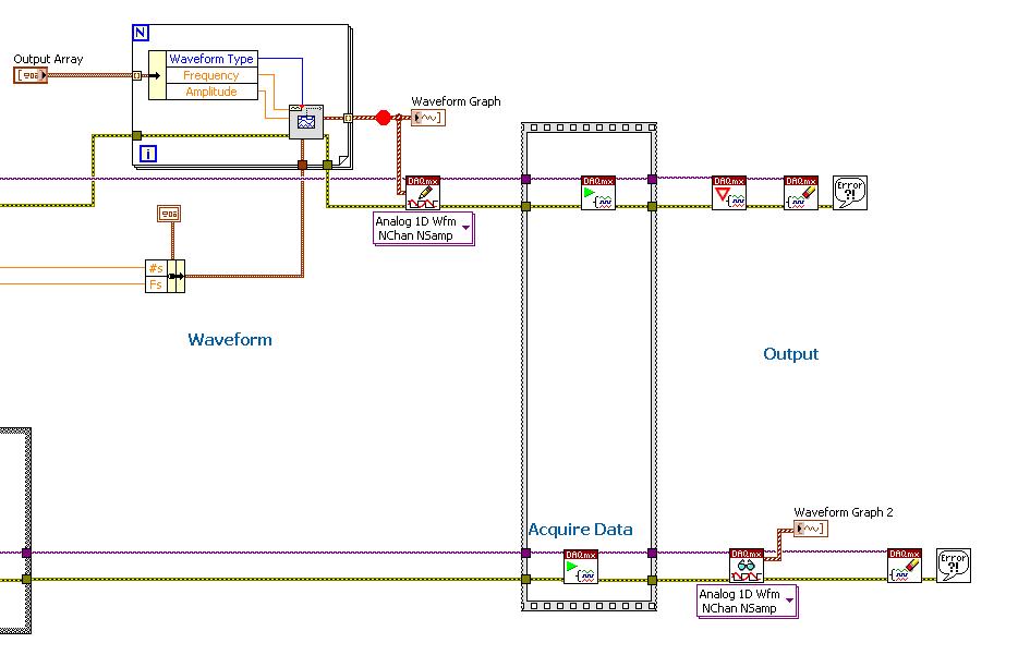
I am writing a piece of code to use an NI USB-6251 data acquisition to measure the speed of sound in water. To do this, I send a burst of cycles say 4 or 5 of a sinusoid analog out on one of the outputs of the acquisition of data and then listening to the signal returned to one of the analog inputs. My problem is that the bits of send/receive of the code are not run simultaneously - two sub VI in the flat sequence structure (screenshot below) still to run sequentially. Is there an easy way to get these to perform simultaneously? I use the VI of Timing DAQmx in both strands of the code. The upper part of the product code output, low is for entry.
Initially, I thought it was a problem of reentrancy, but I put their properties to allow multiple instances of the same VI to open at any time.
Any help would be greatly appreciated.
You do not show the left side of your diagram when you configure tasks. You want to do a task depends on the other for its release of start. You start the dependent task, and then start the independent task. At the start of the independent task, it triggers the other task. That will start them at the same time. They can always run at different frequencies of sampling. If you want to that they are leaving at the same time and use the same frequency of sampling, then you should also share the independent task sample clock and use it in the dependent task.
Take a look at the following article for an example get two tasks to start at the same time. The task of output is the dependent task and the task of entry is the independent task.
https://decibel.NI.com/content/docs/doc-26326
Tags: NI Software
Similar Questions
-
How to synchronize the analog input and the output of two different USB data acquisition boards
Hi all
I have two tips very different USB NI USB 6008 case, which I use to acquire the data (analog input) and a USB of NI 9263 is a output analog only site I use to route a signal (in this case a square pulse). The reason why I use the outputs analog 6008 is because I need to deliver negative tension and need the full +/-10 v range.
Looking at similar positions, I'm pretty sure that I can't use an external trigger or a common clock, I also tried to use the timed synchronization of the structures but no cigar.
I'm including a quick vi I whipped showing how the jitters because of the lack of synchronization signal. The OD of the 9263 connects to AI in the 6008 in this example.
I talked to a specialist in the phone and tols me that's not possible.

-
Hello
I want to generate the continuous signal and at the same time I want to read that signal that I generate using a single card DAQ. I want to generate signal and the received signal is synchronized and in phase.
I looked at several samples on the sync, but it quiet confusing. One using the same clock of entry while the other use a trigger to start. I use the PCI-6024E DAQ card.
Can someone help me in this regard?
In two of these screenshots, the task to HAVE started first (that's what you want, because it is the task of the slave).
Typically for AO, you can simply write a unique period of your waveform, and then regenerate again and again. Your waveform would be preset before the task starts. If you need to update the waveform on the fly according to enter programming during execution of the task, you would disable the regeneration. In addition, if the wave form is such that it cannot be easily represented by a predefined buffer (for example, it is a strange frequency which is not a same ditch at the bottom of the sample clock), then non-regeneration is the way to go.
Best regards
-
Synchronization of analog and digital output with the external sample clock
Hello
First of all sorry for my English, I will try to explain what I want to do.
I want my PCIe-6321 to send two custom signals (modification sawtooths) on a mirror controller. I would also like to generate output with my card at the beginning of each tooth of saw. Everything must be synchronized with an external k-clock signal of 100 kHz. The idea is that whenever the PCI receives a trigger to external clock, it sends two analog output voltages and when he received 1024 clock ticks it will also send a pic of triggering TTL. What I do is first prepare the map and after that in a loop sending and modifing the output values of the two signals and at the same time send a digital signal Boolean in each arch, so when's done it 1024 iterations of the loop I send an event to the digital port. Attached you can see.
The problem is that I don't know how to synchronize both. Can I use the sample clock just to the analog output? I can use sample for the two outputs clock, or do I need to use the output of the meter? If don't know how to use it here.
If I do nothing else bad/wrong, I would be grateful for feedback.
Thanks in advance,
PabloI don't know how but I find the solution. I'm generating more than a positive value (as I was triggered maybe very fast the oscilloscope has been absent there). If I put the sample clock of digital output to use the sampling/ao/Dev1 clock that it doesn't, but if I put to use the same source as the OD (terminal where my external clock is connected), but the trigger to start the DO to be Dev1/ao/StartTrigger this works. I don't really know why, but it does.
Thank you for your patience and your help. I put here the final code.
-
To input analog shutdown when the analog output is completed and synchronization
Hello
I'm trying to get my LabVIEW program to send analog output to a computer and read acceleration using the cDAQ-9184. Chassis output that I use is the NI 9263 and the chassis of entry is the NI 9234. I generate a signal of white noise using LabVIEW Express signal generator.
The first problem I have is the synchronization. I had an old VI that has begun to measure the acceleration just about a second after the entry has been given to the machine. I used the LabVIEW tutorial on how to sync the analog input and output, only to discover that it does not work with two different hunts. Then I found another tutorial that shows how to synchronize different frames between them.
The second problem is the cessation of the LabVIEW program. What I want to do is to generate the signal and then simultaneously send and read the input and output analog, respectively. It is because I don't want a phase difference or any shorter signal for a direct comparison. But as soon as the signal is sent to the machine, I want the entry to stop analog playback and then then the LabVIEW program must stop. I want to be able to choose any length of signal to be generated and stop as soon as the entire duration of the signal has been sent to the machine.
I tried 'DAQmx stop', "DAQmx Timer" and 'DAQmx's task made?' and none of them have worked for me. It is also my first time on a forum posting, so I hope I gave enough information. I enclose my VI as well. The VI shows I read an entry for the analog input voltage, but I am only using this to try to get to the work programme.
I'd appreciate any help I could get.
Thanks in advance
Peter
Hi Peter,.
I have some recommendations for you that I think you will get closer to your solution. First of all, I assumed you meant that you had 1 chassis (cDAQ-9184) who had two modules in it (NOR-9263 and NOR-9234). My next steps are based on this assumption, so if it's wrong, please let me know.
For your first question about the synchronization, the code you provided is very close to what you need. You need to do, however, implement architecture master/slave for startup tasks DAQmx functions. To do this, you can add another frame to the flat sequence structure and put the master start task (input voltage) after the start slave (output voltage) task.
To manage your second question and that the program ends at the point where you, the first step is to get rid of all the logic that you use with the local variable of length of time. Rather than use this logic, just wire the node "task performed?" of "is task performed?" operate to stop the loop. This will cause your loop to stop as soon as the signal is sent to the machine.
I have some other recommendations for you that will increase the performance of your program:
(1) rather than writing on file inside the last loop, you can use the DAQmx Configure Logging (PDM) .vi. You will place this VI between DAQmx Timing.vi and DAQmx Start Task.vi to the task of the analog input voltage.
(2) after the last while loop, you want to stop the task and analog outputs as well with another DAQmx stop Task.vi.
(3) rather than using a local variable for the entrance of displacement and wiring it in the DAQmx Write.vi, you can wire directly from the output waveform of the wave to build function node.
That should help you get started in the synchronization of these tasks.
-Alex C.
Technical sales engineer
National Instruments
-
How to synchronize the device with an analog input device?
Is it possible to synchronize a device (e.g. Basler scA640-70fm, IEEE 1394 b or NI 1722 smart camera) with an input device analog (for example, NI PCI/USB-6225 or NI PCI/USB-6255)? For example, it is important to a video image of match with a sample of data digitized by the A/D converter. In particular, it is important to know when the first video image starts compared to samples of digital data. If it is possible to synchronize the camera with the A/D device, then then how is it?
Thank you
Ian
Hello Robert,.
Thank you for reference and information.
Ian
-
Synchronize the clocks of 2 PCI cards for analog inputs with e/s digital reference
I'm trying to synchronize the clocks of reference of 2 PCI cards so that the analog inputs are synchronized. However, my appilcation has also digtial e/s on two cards, and who apparently made the mistake DAQmxErrorResourcesInUseForRoute_Routing. This discussion describes a similar problem, but the solution was to just put the reference clock to the slave device, who had no other tasks running on it, so what mine does.
Is there way I can synchronize the clocks of refernce without interfering with the digital I/o?
Thank you!
PS: My application is in C++.
The reference clock is really a lower-level component that is shared by all resources on a given device. All tasks on a given device must use the same reference clock. So if you use DAQmxSetRefClkSrc for a task, you can use it to set the same value for your other tasks.
Best regards
-
How to synchronize the start of the acquisition of two cards of different daq hardware
Hello
I'm running a continuous acquisition with a PCI-6133 (@2,5. MECH / s per channel, 8 channels) and a PCI-6259 (@250 ksps / sec per channel, channel 3). Both performed in the same loop. The raw data from the data acquisition boards are written in a separate file PDM. Because the sampling frequency of the 6133 is 10 times higher than 6259, each loop, the number of values read from the 6133 is 10 times higher than 6259. If I look in the tdms file, I see the two acquisitions does not begin at the same time.
timestamp of the acquisition
PCI-6259: 02.06.2016 13:09:14, 866
PCI-6133: 02.06.2016 13:09:14, 941
Also, the number of samples of the 6133 is not 10 times higher.
number of samples
PCI-6259: 4949658
PCI-6133: 49309378
questions
-How can I synchronize the beginning of acquisition? Are there some tutorials?
-What could be the reason why the erroneous report of samples (should be 10 between the daq cards)?
Thank you very much.
Michael
Hello Michael,
the beginning of the acquisition can't at the same time as you do not use a common trigger. If you adjust for the different start time, the difference in the number of samples is only about 300 samples (0, 075 s difference at the beginning of the acquisition, which amounts to 187500 samples).
This difference of 300 samples occurs because the schedules of the 2 cards are not synchronized.
If you want to synchronize the starting and the acquisition between 2 cards, you need to connect with a cable RTSI. In this way, you can route the 1 device to another sample clock. The delivery of the sample through the RTSI cable clock is done automatically by the DAQmx driver.
You can get more information in this section of documentation: http://www.ni.com/product-documentation/4322/en/#toc9
-
NEITHER 6052e: can I re - route the analog output of DAQ for PFI?
Hello
Does anyone know if it is possible to route analog output to one of the PFI (e.g. PFI0)? I use NEITHER 6052e and I would do the following: 1) output a signal to DAQ0; 2) then a few hundred milliseconds a signal of DAQ1; and then 3) read out a simple analog pulse on any output connector external to trigger an external device.
Thank you very much for your help!
Hello sometimes.
Could you please provide more information about your hardware configuration:
What devices are DAQ0 and DAQ1?
Are you using a PXI and PCI 6052?
When you say AO reroute to PFI do you mean you're trying to wire AO into a PFI line for release purposes or are you trying to exit and the analog signal of a PFI line?
-
synchronize the inputs and outputs on the USB-4431
Hello
I have an application that needs to send a signal on the USB-4431 and then capture it with an entry on the same device.
Aware that I use two tasks to do this, one for input and one for output. I discovered that a trigger (on the RTSI bus) can cycles of sending/capture sychronisé departure operations so that it can be a constant offset between the captured signal and the output signal.
Unfortunately, the code I found is for Matlab. I can't find an equivalent for it in the C API of NIdaq. The method is described here; http://www.mathworks.in/help/daq/synchronize-analog-input-and-output-using-rtsi.html.
What I can't understand is how to implement this on the analog input:
ai.ExternalTriggerDriveLine = 'RTSI0';
Can someone shed light on how to do it?
The rest of the things described here, seems to be feasible with a normal trigger:
ao.TriggerType = 'HwDigital';
ao.HwDigitalTriggerSource = 'RTSI0';
ao.TriggerCondition = 'PositiveEdge';
Thank you
Nirvtek
You can synchronize the HAVE and AO by sharing the start of relaxation between your two tasks.
Choose one of your tasks as the "master" and the other to be the "slave" (any).
Set up a trigger to start of digital dashboard on the task of the slave, and set the source of the trigger to be the trigger of the master's departure.
Assume the following:
The name of your device is 'Dev1 '.
I is the main task
AO is the task of the slave
Here's what you would do to sync the two:
(1) create the tasks I and AO in order that you want to
(2) set up "timing" on the tasks of HAVE it and AO (you choose the sampling rates must be the same or power-of-2 many of the other (for example 100 K, 50 K, 25 K, 12.5 K, etc...))
(3) configure your slave (the task of AO) task to have a numerical advantage start trigger and make the source is the trigger for the start of the task of the master (the task to HAVE it). In our case, "Dev1, AI, StartTrigger.
(4) write data (a sine wave, presumably) to your task AO
(5) start the task from the slave (the task of AO). The task of the AO is now in the 'Started' State, but given that you've set up a digital trigger early, it won't actually generate data until he sees a numerical advantage of 'Dev1, AI, StartTrigger.
(6) to start the main task (task to HAVE it). The task of the AI does not have a trigger digital early, so the software will immediately generate a start trigger, which also causes a numerical advantage on "StartTrigger/AI/Dev1", which causes the task AO start at the same time.
7) read your job to HAVE.
You will notice a few 0 at the beginning of your data to HAVE. It's a result of something called "Filter Delay" and it is an inherent characteristic of all DSA devices - see the manual to use DSA and this article for more information on what is and how to cope.
I hope this helps.
EDIT: I just noticed that you pointed out an existing C example. It's exactly what you want. I don't know why you have a resource error booked - I tried it myself and (after changing the AO will of +/-10V to +/-3 .5V), it works beautifully. Try to reset your device to the MAX (or DAQmxResetDevice() of your program)
-
Synchronization output analog and an entry for imaging
Hi all
I'm stuck in my higher studies project and really need help. I tested an imaging system, where one uses two mirrors MEMS to analyze the sample and a tube set (PMT) allows to acquire voltage signals and translate them into images of scanning laser.
I use the same DAQ card for input and analog output. The DAQ card sends features X and Y of the MEMS mirrors so that the reason for scanning 2D starts left to right and up and down.
Scanning rate: 131500 pixels per second.
Size: 1170 by line, 514 ranks in total pixels.
Thus, the mirror will scan 601 380 pixels per image, which takes approximately 4.57 seconds to complete. I almost finished this part in LABVIEW.
However, only a part of the scanned pixels are read by the PMT. We want to get an image of 512 x 512 pixels. For example, the PMT works like this:
(1) the sampling rate is also 131500.
(2) skip the first row.
(3) starting at the second row, the PMT will jump the first 329 pixels, read in the next 512 pixels and skip the rest 329 pixels again. Then, it moves to the next line.
(4) jump the last row.
My approach in the plate sequence
(1) ignore the signals of all 841 (1170-329 = 841).
(2) create a loop for, run 512 times.
(3) in each loop, first jumping 658 signals (329 x 2), then read the signals then 512 MB.
(4) wait 1499 pixels left to complete the digitization (1170 + 329).
Problem
The mirror and PMT must start and finish at the same time running. However, when I run my VI for the analog input and create the image on the Panel, it takes 5.7 seconds to complete, which means that they are not at all synchronize. It seems that there is some unexpected time in the loop for, but I don't know how to change the code to meet the requirement of calendar.
Please see the attached VI. Any help is greatly appreciated.
~ Sheng
My approach in the plate sequence
(1) ignore the signals of all 841 (1170-329 = 841).
(2) create a loop for, run 512 times.
(3) in each loop, first jumping 658 signals (329 x 2), then read the signals then 512 MB.
(4) wait 1499 pixels left to complete the digitization (1170 + 329).
Consider this: add up all these pixels, both those you want to record and those you want to ignore.
If I read you right, that would be:
841 + 512 * (658 + 512) + 1499
Regardless of this number, set up a task that many samples and record the whole bloody thing. Let the time of equipment for you.
Then, AFTER that data are in hand, pass by and throw the first 841 points, then for each loop, throw away 658 and keep 512... etc.
IOW, let the MATERIAL which made the better material: precise timing.
Let the SOFTWARE do what does best software: weird logic.
-
Open a synchronized session of the analog inputs and position
I want to read 8 analog inputs (only three IA in the capture of code) with a PCI-6221 card at a rate of 100 samples/s, reading 10 samples/iteration. At the same time, I want to read the position synchronized with the analog inputs. Is this possible? If I just merge the position with the analog signal I get 10 readings of position for each 100 analog input readings (see chart - Red's position). For the control of the movement, I use the pci-7342 with UMI-7764 interfaces. Could someone help me out here please?
Not necessarily. As said, speeds of up to 200 Hz should work fine with a 7342. If this is not enough, of course a 7350 could be used, but there is also a completely different approach that should work with your current hardware:
7342, you may also route the phases of encoder to the pins of the RTSI. You can use a counter on the 6221 to measure the position of your axis based on the singlas you have routed the RTSI pins. Now you can use "Measure of Position buffered" (see DAQ examples) to measure the position with the same source of synchronization than your analog signals.
I hope this helps,
Jochen
-
How about using labview vi of the filter and multiply vi to replace the analog filter and amplifier
Hi all
I use a data acquisition system to acquire a weak signal, it seems to a voltage amplifier and low-pass filter before the acquisition of data. I was wondering, if I use low-pass of the labview vi of the filter and multiply vi to process the signal picked up by DAQ, can I get the same effect as the analog low-pass filter and amp?
Thank you!
No!
1. any system of sampled data must be band including prior to sampling in order to avoid aliasing. It is impossible to remove aliasing after collection.
2. the resolution of the DAQ system will be so low that you'll very 'fat' scanning and you will lose a large part of the information in your signal.
Sorry, but you need to amplify and filter in the material before the data acquisition device for best results.
Lynn
-
How can I check if the counter entry is synchronized with the analog output?
Hello
I'm working on an application for counting photons. I use two channels of analog output on a PCI-6713 card to send a frame model to a set of XY scan mirrors. I then a photon count unit that emits a TTL signal when the photons are detected as a result of this raster analysis. I then use a surfboard USB-6211 to count the edges on this TTL signal.
I have problems that seem due to synchronization problems. I use the sample AO on the PCI-6713 card clock like the door of my meter on the map USB-6211. I use a trigger to start digital to analog output and a trigger of arms for the entrance to counter early. Is there a way to check that the analog output and counter entry of start of operations at the same time and are are synchronized? I basically want to monitor and compare the ao real sample of the PCI-6713 card clock door signal used by the jury of the USB-6211. I was able to export the sample AO clock and watch it on my oscilloscope, but not the signal from the door of the USB-6211.
Thanks for your help,
Brian
Update... It turns out that there is no problem of synchronization between my meter input and the analogue output. There was a difference of impedance when I connected my unit of counting photons to my USB-6211. This caused an error variable count rate. After accouting for this shift, the problem disappeared.
-
Synchronize two E-card with traditional DAQ series
Hello
I have a PCI-6052E and a PCI-6071E and I have a Matlab program that interacts with traditional hardware DAQ driver cards.
It is possible to synchronize the two cards use RTSI or something? If so, what should I do in matlab to achieve?
I'm a bit confused, because I don't know if this is only possible using DAQmx.
Thank you!
Hi zlyhere,
Using DAQmx would definitely be the best choice.
In terms of using C vs the Data Acquisition Toolbox for The MathWorks Inc. Matlab® Software, I would recommend the Toolbox for ease of use. The MathWorks develops the Toolbox, so they must have documents on how the maps can be synchronized.
If you find that you need more features, you can fall back to C. Documentation is available at
"" "" Start menu"all programs" National Instruments "NOR-DAQ" support textual Code ' using NOR-DAQmx C reference
MATLAB® is a registered trademark of The MathWorks, Inc.
See you soon!
Maybe you are looking for
-
Why can't have buttons "View your best sites" on the start page?
Title sums it up! Start page basically sits there and need to open a second tab to see the 'Top Sites' buttons for quick access. Seems to be an unnecessary step without reason.
-
Best way to transfer strings, arrays and clusters
Hi, I just want to know the best way to transfer strings, arrays and clusters between a PC and a computer-RT (compactRIO) if I want to use them in deterministic loops: For a string should I use a published network shared variable flow or network? For
-
Cannot get online after installing windows XP Edition family on my laptop which was origally XP PRO
I have a laptop HP Compaq 6830 s that had xp professional did not get a disc of bone with it when buying. The system crashed 0x0000007B error code. I installed OS XP Home version Pro Version and now I't does not recognize my modem or ethernet. Cannot
-
Unrecognized 8 GB SDHC card & the patch (KB934428) does not solve the problem.
I have a CoreMicro SDHC 8 GB card for my new camera from Pentax but my HP computer (running Windows XP SP3, with 5 built in card reader) will not recognize it. I loaded the patch (KB934428) but it does not solve the problem. Please help me solve th
-
After that I turned on my computer, I get this error message... "Windows cannot find C:\Program Files (x 86) \Search Extensions\Client.exe make sure you typed the name correctly and try again." It all started October 1, 2014, and I have no idea why.