Open a synchronized session of the analog inputs and position
I want to read 8 analog inputs (only three IA in the capture of code) with a PCI-6221 card at a rate of 100 samples/s, reading 10 samples/iteration. At the same time, I want to read the position synchronized with the analog inputs. Is this possible? If I just merge the position with the analog signal I get 10 readings of position for each 100 analog input readings (see chart - Red's position). For the control of the movement, I use the pci-7342 with UMI-7764 interfaces. Could someone help me out here please?
Not necessarily. As said, speeds of up to 200 Hz should work fine with a 7342. If this is not enough, of course a 7350 could be used, but there is also a completely different approach that should work with your current hardware:
7342, you may also route the phases of encoder to the pins of the RTSI. You can use a counter on the 6221 to measure the position of your axis based on the singlas you have routed the RTSI pins. Now you can use "Measure of Position buffered" (see DAQ examples) to measure the position with the same source of synchronization than your analog signals.
I hope this helps,
Jochen
Tags: NI Hardware
Similar Questions
-
Toggle the analog inputs and tasks of output on the same card in LabView
Hello
I'm relatively new to LabView and am trying to find the best way to switch between reading and writing tasks on my PCI-6024E. It seems this would be a common thing to do, but I found no good documentation or any relatable example program. Basically, I would like to be able to monitor certain analog inputs and then write that some outputs if an entry is in accordance with certain specific conditions (say > 4 Volts voltage). It is my understanding that you can only signal (input and output) types associated within a single task in DAQmx. I also understand that you cannot have multiple tasks running at the same time on the same material/map, otherwise you get a: 50103 error 'The specified resource is reserved. Calendar is not really all that matters to me, but quite synchronous and effective would be nice.
I have attached a sample program that shows more or less what I'm trying to do. I want to follow several analog input lines (AI0 AI1, AI2 and AI3 and) effectively at the same time. If certain conditions are met, AI3 > 4 Volts, then write 5 Volts for analog AO0 and AO1 outings. I also want to maintain output at 5 Volts up to AI3 falls below 4 Volts. Is there a better way to pass the task to read and write than what I've done here? In a sense, all I really do is toggle of a state machine if the required conditions are met and if start/stop tasks of reading/writing necessary.
One last question, is there a way to display the four channels in the waveform graph using the 1 d NChan 1Samp mode so I can have a time chart and indicators?
P.S. I'm under LabView 2011 on Windows 7. Your ideas and suggestions are appreciated.
Thank you
KJ
I also understand that you cannot have multiple tasks running at the same time on the same material/map, otherwise you get a: 50103 error 'The specified resource is reserved.
This is incorrect. You can't have two tasks of the same type running on a single card. You can have an analog input and analog output task running simultaneously on the same hardware.
You are right that each task can have only one type of task (entry or exit). Discover DAQmx examples in the example Finder to get examples of synchronized input and output.
PRO TIP: In the Finder of the example, go to the drop-down list in the lower left corner. Pull down and select Add Hardware. In the pop-up window, add your PCI-6024E to the right pane. Click OK in this window. Then in the main window of Finder example select your hardware from the drop-down list and check the filter results by the hardware. The example Finder then only you will show examples that are out-of-the-box compatible with your hardware. I am sure you can find something to fit your needs here.
-
How to synchronize the analog input and the output of two different USB data acquisition boards
Hi all
I have two tips very different USB NI USB 6008 case, which I use to acquire the data (analog input) and a USB of NI 9263 is a output analog only site I use to route a signal (in this case a square pulse). The reason why I use the outputs analog 6008 is because I need to deliver negative tension and need the full +/-10 v range.
Looking at similar positions, I'm pretty sure that I can't use an external trigger or a common clock, I also tried to use the timed synchronization of the structures but no cigar.
I'm including a quick vi I whipped showing how the jitters because of the lack of synchronization signal. The OD of the 9263 connects to AI in the 6008 in this example.
I talked to a specialist in the phone and tols me that's not possible.

-
I can't watch the analog inputs in hearing CC 2014
I have a M-Audio M-Track more USB audio interface. Digital interface output is connected via coaxial RCA to my receiver. The analog inputs normally receive a signal from a phono preamp line, since I transfer a lot of vinyl to the computer to listen to in my car and my phone.
The thing that I'm trying to understand is why the hearing does not allow me to monitor the analog inputs. I can monitor them very well when I use Studio producer One of the Presonus. But the hearing does not allow me to follow, although it does not record the signal and then I can read.
The audio device at the hearing, I've chosen is the ASIO of M-Audio driver. Under audio mapping I can't select anything other than the analog inputs and outputs. It is not an available digital output, which could be part of the problem, perhaps hearing does not allow the signal to convert analog inputs to the digital output. However, as I said a producer Studio control perfectly well, so the analog/digital real-time monitoring is allowed by the device.
My hardware is PC with Windows 8.1 Pro 64 bit, i7 3930 k, 32 GB RAM, card mother Asus P9X79 Pro, and some other stuff that wouldn't really make a difference in this problem.
Any ideas?
Thank you
Sebastian
Try recording in multitrack view and by clicking on the little 'I' (Input) button at the left end of the track. It should route the signal from input to output for monitoring.
I have the background track M, no more, so I can't try it but I think it should work but with a bit of latency (which shouldn't be a problem since you're not dubbing.
-
analog input and output synchronization
Hello everyone, I seem to have a problem of synchronization of the analog input and output on my M-series USB-6211. My request is quite simple. I want to the production and to acquire a sinusoid at the same time. Theoretically, I should have the same 4000 data points through the input and output channels. The reality, however, captured on an oscilloscope, shows that the analog output is off more than 4000 data points. The entry (acquisition) shows 4000 samples. Please see below an excerpt from the creation of task, timing and execution. I'm afraid that the analog input and output are not attached correctly. Do you see something suspicious? Thank you very much! The task was created: DAQmxCreateTask("",&inTaskHandle); DAQmxCreateTask("",&outTaskHandle); Analog output channel Configuration, with 20Ksamples/s: DAQmxCreateAOVoltageChan (outTaskHandle, physChanOut, ' ',-10, 10, DAQmx_Val_Volts, NULL); DAQmxCfgSampClkTiming (outTaskHandle, "OnboardClock", 20000, DAQmx_Val_Rising, DAQmx_Val_ContSamps, 4000); Configuration of the analog input strings: DAQmxCreateAIVoltageChan (inTaskHandle, physChanIn, "", DAQmx_Val_RSE,-10, 10, DAQmx_Val_Volts, ""); DAQmxCfgSampClkTiming (inTaskHandle, "OnboardClock", 20000, DAQmx_Val_Rising, DAQmx_Val_ContSamps, 4000); Set up the trigger: sprintf ("/%s/ai/StartTrigger", local_port, deviceName); DAQmxCfgDigEdgeStartTrig (outTaskHandle, local_port, DAQmx_Val_Rising); Output: DAQmxWriteAnalogF64 (outTaskHandle, (numberOfSamples * oversample), 1, 40, DAQmx_Val_GroupByChannel, input, & sampsPerChanWritten, NULL); Acquire: DAQmxReadAnalogF64 (inTaskHandle, 4000, 40, DAQmx_Val_GroupByChannel, readArray, 8000, & sampsPerChanRead, NULL); The tasks stop: DAQmxStopTask (outTaskHandle); DAQmxStopTask (inTaskHandle);
Hello
Change the finished continuous sampling method seems to solve the problem:
DAQmxCfgSampClkTiming (inTaskHandle, "OnboardClock", 20000, DAQmx_Val_Rising, DAQmx_Val_FiniteSamps, 4000);
Also, I wanted to say earlier to write 4000 samples:
Output:
DAQmxWriteAnalogF64 (outTaskHandle, 4000,1, 40, DAQmx_Val_GroupByChannel, input, & sampsPerChanWritten, NULL);
Thank you
-
I am acquiring several channels of analog voltage input at the same time, I need to send an output analog two seconds after the start of the entry.
I'm running an experience with accelerometers on a query table.
I start the trigger and the table remains still for two seconds, which allows a reference level for all sensors.
Then the output signal of the VI removes the break in the motor controller.
The speed measured by the encoder is sent to one of the input channels.In this way, our accel and speed data are synchronized.
After it acquired the analog input data out put must be reset to zero.
MULTI.vi I've updated the link above works of VI, I used a property node to solve the problem.
-
Good day to all,
I use NEITHER-7350, LAbview 8.5 and try to measure the voltage from a power source.
Is there a screw that read the analog inputs. I can't open the examples.
Thank you
Have you watched the DAQmx? Create a virtual channel, start the task and read the value.
http://zone.NI.com/DevZone/CDA/tut/p/ID/5370
-
How do I get the analog input signal and send it to output analog (real time)
Hello world
I do a simple task in Visual C++ and I use PCI-6221(37 pin).
Basically, I want to send the same signal of "analog input" to the "analog output".
at the same time (or almost), to make real-time application.
Can someone provide me with sample program please.
I would be grateful if you could provide me with the great tutorial that explains
step by step everything about NOR-DAQmx for C/C++ programming.
Best regards
Khassan
This is my code in C++, you can optimize it if that seems too messy. This code reads the analog input signals and exports it through the analog outputs.
To make this code additional work of the directories include and library directories must be added to OR.
I hope it helps someone.
#include
#include
#include "NIDAQmx.h".
#include#define DAQmxErrChk (functionCall) {if (DAQmxFailed (error = (functionCall))) {goto error ;}}
int main (int argc, char * argv [])
{
Int32 error = 0;
TaskHandle taskHandleRead = 0, taskHandleWrite = 0;
Read Int32 = 0;
float64 context [1000];
char errBuffRead [2048] = {'\0'};
char errBuffWrite [2048] = {'\0'};
bool32 done = 0;
Int32 wrote;DAQmxErrChk (DAQmxCreateTask("",&taskHandleRead));
DAQmxErrChk (DAQmxCreateAIVoltageChan(taskHandleRead,"Dev1/ai0","",DAQmx_Val_Cfg_Default,-10.0,10.0,DAQmx_Val_Volts,NULL));
DAQmxErrChk (DAQmxCfgSampClkTiming(taskHandleRead,"",100.0,DAQmx_Val_Rising,DAQmx_Val_ContSamps,0));
DAQmxErrChk (DAQmxCreateTask("",&taskHandleWrite));
DAQmxErrChk (DAQmxCreateAOVoltageChan(taskHandleWrite,"Dev1/ao0","",-10.0,10.0,DAQmx_Val_Volts,NULL));
DAQmxErrChk (DAQmxCfgSampClkTiming(taskHandleWrite,"ai/SampleClock",100.0,DAQmx_Val_Rising,DAQmx_Val_ContSamps,1000));DAQmxErrChk (DAQmxStartTask (taskHandleRead));
DAQmxErrChk (DAQmxStartTask (taskHandleWrite));While (! fact &! _kbhit())
{
DAQmxErrChk (DAQmxReadAnalogF64(taskHandleRead,1,10,DAQmx_Val_GroupByScanNumber,dataRead,1000,&read,));
DAQmxErrChk (DAQmxWriteAnalogF64(taskHandleWrite,read,0,10.0,DAQmx_Val_GroupByChannel,dataRead,&written,));
}
_getch();Error:
If (DAQmxFailed (error)){
DAQmxGetExtendedErrorInfo (errBuffRead, 2048);
DAQmxGetExtendedErrorInfo (errBuffWrite, 2048);
}
If (taskHandleRead! = 0){
DAQmxStopTask (taskHandleRead);
DAQmxClearTask (taskHandleRead);
}
If (taskHandleWrite! = 0){
DAQmxStopTask (taskHandleWrite);
DAQmxClearTask (taskHandleWrite);
}
If {(DAQmxFailed (error))
printf ("error DAQmx: %s\n",errBuffRead); ")
printf ("error DAQmx: %s\n",errBuffWrite); ")
}
printf ("end of the program, press the Enter key to quit\n");
GetChar ();
return 0;
} -
Registration of the analog inputs in continuous (Clipping)
Material:
(1) USB NI CDaq-9174 chassis
(2) NEITHER 9234 Analog Input Modules
(1) digital input module 9402 OR
Goal/Requirements:
To read the analog inputs continuous only in digital input is "high".
Problem:
Timestamp in log file prooves that logging is not continuous. It seems that the first seconds of 0.6 of every second is recording, I guess the other 0.4 is used to write custom? I can't use VI SignalExpress for this application because logging must be triggered by a high digital input.
File is attached. Thank you all!
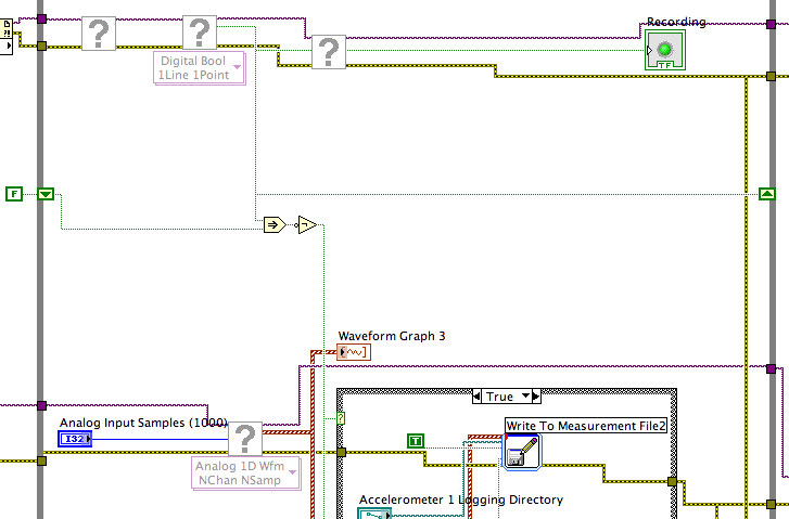
To detect changes in the digital input, you need to compare the current value to the previous. The easiest way to do this is to plug the output of digital playback on a shift register. The Boolean function involves will tell you when a transition has taken place. See the central part of the image below. If you exchange the true and the false case of case structures, you not the inversion function. Look at the help file for more information on what the function actually implies.
You must also change the wiring of the name of input for writing custom file FIle.vi so that the name is automaticlly changed. Depending on what you want the naming system to be, that it can be simple or rather complicated.
Lynn
-
Analog input and contrary to the worksheet
Hello
I m trying to get an analog input (volts of a sensor) and a counter with an encoder. I ve long time looking for a solution and I ve already found some very useful examples that I ve used on the VI (thanks for that
 ).
).The program is very close to what I want, but there are still a number of things that I don't understand (I m very new with labview and I still Don t know exactly what I m).
-J' read in an example here that I should use "Single Point timed material" and use the "wait for next sample clock VI' to get samples always with a period fixed (rate). It's works! Before, I used "continuous sample" and it was a bit jitter. Well, could someone explain to me please what is the difference between continuous and timed, material and how the 'Harware Timed Single Point '.
-My second question is about the string formats that I receive on the loop of the wave. I ve tried with very different formats, but it doesn´t work as I expected. I have a format string like this on the 'Date Format VI': %S % 3u-online seconds with 3 decimals?
And on the format I have on the 'picture to a worksheet VI string' should I used %5.7f to get 5 decimals on the output (spreadsheet file). Why?.
What I m trying is to get the analog input with counter clock (I think I already do), given a graph and a file with lines of 3: 1 °-time with 3 decimals, 2 °-v with 5 decimals (positive and negative) and 3 °-position (positive and negative integer).
Software: Labview 2013, pilot DAQmx 9.8, Windows 7 32-bit
Material: NEITHER 6321 PCIe, Intel Quad 9550, 4 GB RAM
I hope that his undestable, I should learn some English to.
Thank you
Hello
Thanks again for the response. I tried to implement the code as you say, but it's always a mistake to time. I solve it with a timestamp.
The idea of a producer consumer loop was very good. After"a bit", I managed to solve it too. Here's the code.
Thank you
-
How to read the analog inputs of one Board of R for (PXI-7851R) series
You can guide me please with the steps for reading of the analog inputs of a series a. card I use as the target fpga PXI-7851R.
Have you looked at the examples provided with LabVIEW? There are examples showing how to read the analog inputs.
-
What is the analog input of the NI PCI-6229 impedance?
I am trying to determine the effect of a 12 K resistor that is in series with an analog input of an NI PCI-6229 data acquisition card. Resistance of 12K seems to be part of a RC filter. I have a 0-10 VDC source this supply circuit. What is the impedance of the analog input of the NI PCI-6229 data acquisition card? If it makes any difference, the analog input is connected in differential mode with a 180K resistor to Gnd AI.
Thank you
RWB
Hi, RWB,.
The input impedance is classified in the specifications 10 GOhm. So, the effect of your k 12 resistance should be relatively low. Take care!
-
Analog input and output using 5640r
Hello world
I'm Christine, I'm implementing OFDM on fpga using 5640r.
The code that I have, which is good in the simulation using labview and also using 'nor 5640r treatment only' but I want to implement in "analog input and exit vi" so that I can send and receive on the same card 5640r
After so much attention in this regard, I am still unable to find the issue, then the soultion to this question. something that I am able to understand that maybe there would be some questions (ADC and DAC) clocks the clock setting
I have attatched that vi. Please take a look at
Concerning
Aqib
College of aeronautical engineering
Risalpur
Sorry
-
Firefox does not open in full screen on the task bar and I have to go over it to see the web page.
Firefox does not open in full screen on the task bar and I have to go over it to see the web page.
Firefox window is sometimes "off screen" somehow. Often, you can force it to appear on the screen by right clicking on the thumbnail image just above the taskbar and choose expand. Does it work?
A possible cause for this is that the file that stores the positions and sizes of window is corrupt. You can delete this file and Firefox will return to standard window resizing.
#1 method: If you can get a zoomed window:
Open the settings folder (AKA Firefox profile) current Firefox help
- button "3-bar" menu > "?" button > troubleshooting information
- (menu bar) Help > troubleshooting information
- type or paste everything: in the address bar and press Enter
In the first table of the page, click on the view file"" button. This should launch a new window that lists the various files and folders in Windows Explorer.
Leave this window open, switch back to Firefox and output, either:
- "3-bar" menu button > button "power".
- (menu bar) File > Exit
Pause while Firefox finishing its cleanup, then rename xulstore.json to something like xulstore.old. If you see a file named localstore.rdf, rename this to localstore.old.
Launch Firefox back up again. Windows normally appear again?
#2 method: If you can not get a Firefox window for all:
Close Firefox by right clicking the icon in the taskbar > close all windows.
Using the Run dialog box (windows key + R) or the start search bar menu type or paste the following and press Enter to drill down to the profiles folder:
%APPDATA%\Mozilla\Firefox\Profiles
Here you can see a folder - in this case, double-click that - or more than one case - in this case, double-click on in what looks like the most recently updated.
Scroll down and rename xulstore.json to something like xulstore.old. If you see a file named localstore.rdf, rename this to localstore.old.
Launch Firefox back up again. Windows normally appear again?
Then, to re - light bars, you can use one of the following methods to view the list of the toolbar, and then select the desired bars it:
- Right click on a place empty on the tab bar (or the button '+')
- Press the Alt key to activate the classic menu bar > view > toolbars
- in customize mode > show/hide toolbars (see: Customize Firefox commands, buttons, and toolbars)
To activate the menu bar, toolbar bookmarks or other bars, click it in the list.
-
Safari can't open what I think is the redirection page and says he does not know how to open the app.
It gives me the following information:OS X does not know how to open the addresses starting with aam
Click on the link below and download Creative Cloud Installer file and use them to install the creative Cloud Desktop application.
https://ccmdls.Adobe.com/AdobeProducts/KCCC/1/OSX10/CreativeCloudInstaller.dmg
Maybe you are looking for
-
Sync info does not stick on the desk and a link shared on Android FF, where on the desktop?
If you don't mind, I have two questions. The first is in what regards to Firefox Sync on Windows 7 x 64. Windows Firefox 19.0.2 won't save my login Firefox Sync. Whenever I start my browser that I put in the key name to username/password / recover. T
-
HP ENVY: I took the tape cartridge error color how to protect? cannot reuse the Ribbon that seems.
I took broadband of the cartridge color by mistake, but I can't reuse the tape. What is the best way to protect?
-
Satellite L500 speaker static noise when playing certain CD
My laptop speakers work perfectly. But for some reason, there is noise whenever I play all the songs from any of these CDs: Showbiz, Absolution, H.A.R.P.P Tour 2008 (all of Muse), it's not a problem with the CD, I played them all perfectly on another
-
Evaluation version so that NIVLM works well
NIVLM works well. Yet the local version of the Labview report (from today ' hui) that NIVLM is not found. and then they start in evaluation mode. The license gives server monitoring: queries go to the license server (so no problems of network/firewal
-
Are there versions of operating system specially built for businesses
I know that RIM makes different OS versions for the different mobile operators. But is there such thing as versions of OS specifically for Blackberry devices businesses? For example, a company not on AT & T device can be upgraded to supported version