Test serial modbus communication
Hello
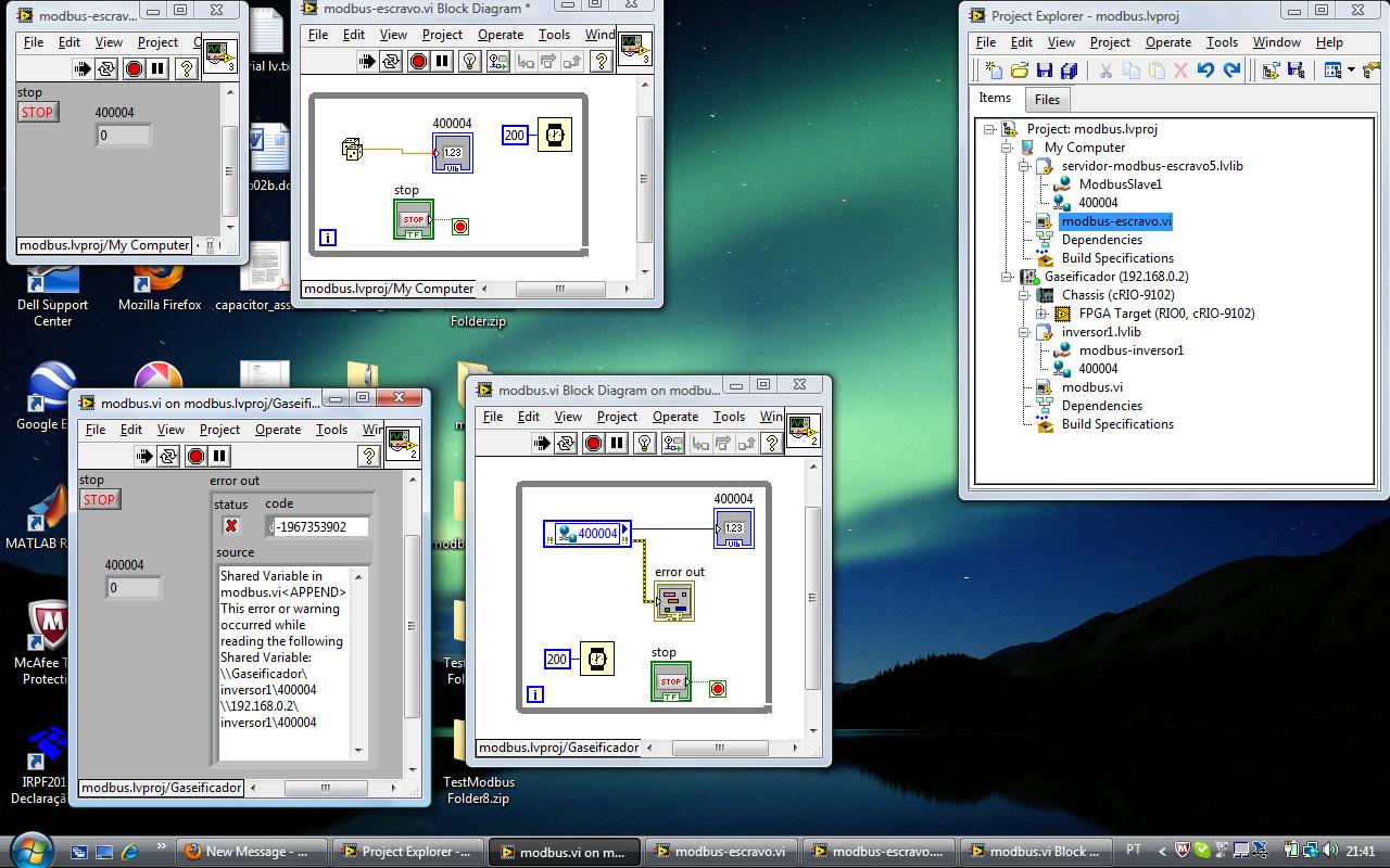
I would like to test server-serial communication modbus master running on the CRIO (9012) and the serial modbus slave server communication.
Issues related to the:
Is this possible? Two VI run simultaneously? If so, what am I doing wrong
The CRIO is connected by ethernet and series with PC.
Best regards
Tags: NI Software
Similar Questions
-
Deal with failure when using LabVIEW 2011 and DSC MODBUS communication
I'm currently reading from operating records a PLC with MODBUS/TCP. I confirmed that the PLC will update the values and in response to a MODBUS communication correctly by using a third-party program called Modbus Poll. However, when I try to query the PLC using the LabVIEW shared variable engine, I am unable to read the values of the same addresses that I consult with Modbus Poll.
My installation is simply to a PC directly connected to the controller via Ethernet without a router between the two. I'm using LabVIEW 2011 SP1 with the DSC module.
I opened the Manager of distributed systems OR to display the State of all variables in the Modbus Library that I created, and I noticed that the ILO CommFail permanently the value 'true '. All other variables with a 'read' access mode signal "failure of process". I tried to restart the process and stop and start the local variable engine without success. I also restarted my computer several times to see if any services did not exist, but this does not appear to have solved the problem.
Finally, I resorted to listening to communications on the network card I have the PLC connected via Ethernet using Wireshark and found that while Modbus Poll communicates with PLC, number of MODBUS and TCP packet is sent and received. However, when using only LabVIEW or the DSM OR communicate with the controller, there don't seem to be any communication on the network card.
Something that may be interesting to note is that I could communicate with the PLC and to read values with the DSM just once, when I understood everything first what address I should be reading of. All of this has stopped working shortly after. Prior to this, 'CommFail' was not generally set to 'true' with my current setup. Thinking it was my firewall, I have since disabled my firewall, but this seems to have had no effect on the problem either.
Any help on this would be appreciated.
So, I thought about it. It turns out that the IP address of the server i/o MODBUS must be set to the address of the MODBUS slave, not the local computer. The address of the i/o MODBUS server is defined by the navigation in the Explorer window projects, expanding the variable engine shared library for MODBUS and right click on the server MODBUS (for example Modbus1) item and select Properties.
In addition, the addresses seem to be shifted by + 1.
Thanks for the tip so.
-
Serial RS232 Communication VISA write does not
I am trying to send a SPELL of 5003 01 command to my card that I am logged in via Rs232. This command should get my PCB to change play modes.
I posted about this problem before thinking it was a problem with it not sent in HEXADECIMAL:
It wasn't the problem.
I use the CTS line for flow control. I know that the CTS signal is reaching the computer of my PCB as I tested it and I know that the PCB can send data to the computer I get the answer correct 4 bytes in HEXADECIMAL when I use the reading visa to get my player to PCB data.
I get a 1073807339 error when I try to write even when the read function is disabled.
The only thing I can think is that LabView is not to recognize the signal CTS go down and, consequently, time-out.
I use the good 9600 baud rate, 8 bits of data and no parity, 1 stop bit. I am using RTS/CTS flow control, but the RTS line is not connected. I don't think it should be a problem that RTS is used to indicate the Council when to send data to the PC to my knowledge and is not serious.
FYI the written string section of the VI is unused. The string to write, that's where I'm seizes my "5003 01" command.
Thank you
Kyle
I just thought of it. I had messed up the wiring of the PSTN line. She received the RTS line, I think. I thought I had it correct since the Tx line was correct. Thank you for your help on the problem of the HEXAGON.
-
Server I/O from the VISA against library MODBUS communication approaches
I read several white papers OR on the various ways to interface with instruments of communication using MODBUS.
On the surface it seems to me that the I/O Server is the fast and easy way to put up just to get something. Once I found this so I'll have to determine if I really need an interface more low level. It seems to me that, even with the I/O Server, you can get low level features. But this seems contrary to what white papers.
Someone with a more in-depth experience & knowledge on this subject would be able to provide a brief explanation of this type of low level function, you can not with the server I/O?
Also, what are the advantages/disadvantages to using a VISA interface instead?
As a summary of basic - VISA is the interface on the serial port, allowing you to send and receive data, but not to interpret the data real meaning (layer transport). Both the e/s server and the MODBUS library is a layer on top of that - they use VISA internally to manage the main part of the sending and the reception of the raw data and focus on translating raw data into a meaningful form (Protocol Layer).
If you use VISA directly, you need to add your own logic to translate the General commands modbus in the raw data, that includes the server for transmission and reception, like the server, MODBUS i/o library.
In my opinion, the I/O Server requires authorization (DSC) and the MODBUS library is free.
-
Exstance no of Modbus communication
I work with a rs232 for connection rs485 via a UNO2019 PC box. The RS-485 connection is going to be MODbus RTU, has about 4 slaves on the bus (MMI flowmeter, VFD, two temperature RTD). All theses devices are configured accordingin
9600 baud, odd parity, no flow control. the VISA resource would be COM3.
Now all of these components I worked with every day for numerious months. and VI implementation exists (almost) without error. I get an error code for the additional bytes to the port, but he spends the whole upward. I don't know if I'm not or write, but it has happened in every piece of software, I developed in labview (it does not check the boolean error so I guess that's not important).
Currently, when I try to read the registers of the MODbus slave, I get error:
-107380733 (that mean 100 different things that I have done my research properly, bad bytes to the port, do not use correct end characters in your message). But every time I have seen that error code discussed in question direct USB/RS232, not RS232 to RS485.
The attached string was
3-> MD series Master Query.vi
2-> MB series Master query Holding Register.vi
1-> address Test.vi
Thank you for any light you can contribute on my problem.
Problem has been resolved. It was a hardware problem as I thought. Apperently this code error will exist when your RS-232/485 is hard set via dipswitches do not send data.
-
Modbus communication with a piezoelectric dynamometer
Hello..!
I am a new user of LV and I try to communicate with a piezoelectric dynamometer in modbus RS232.
After you install NI Modbus Library, I created a master VI with labview 8.6 using these libraries and I can get communication with scale, these values are added in the registry U32Bit 1 and it's good, if I press a load cell, I can see the values exceed. (from 0 to 65535). Now, I want to show on the front the weight in KG, as the decimal separator, for a proper interpretation of the value for my client, so I added a block table to unbundle that I convert a value with I32Bit (-32768 a 32768) with a flag, but I don't see not all values...
I guess I did something wrong (conversion), I read a few KB, but I do not see a solution...
Can someone give me a link or information to show me an example to convert this value... ?
Thanks in advance for any help to...
Configuration of master VI:
Read now register
Address starting 2012 (query to get the net value of the load cell)
Quantity 1
Slave address: 1
RTU
9600
3 com
parity none
Can you post some examples of bytes you receive from the Modbus read and you expect that these values are? It's probably just a matter of the right of casting, or the number endianism, or operation of scale that must be done.
-
Another question on serial port communication
Hi all!
I started working with tools of communication series LV (actually, I'm a newbie in LV at all).
The question is - how I effectively detect y at - he new data arrived in the read buffer VISA?
I mean, in the examples I found, there is always a fixed delay between writing series and the read operation - it makes the instrument depends on the speed of communication and (worse) on the response time of the required device. I want to implement is a vi that writes a (or different applications) via a serial port and then check periodically (with the relatively small period, say, 1ms) series read buffer for the response data until new data stops arriving. For this I need to know the number of bytes of data into the buffer, or a property (if any) detecting the arrival of new data.
As I read on this forum (and figured out from my own experience)-using VISA bytes to the Serial Port is ' t a good idea
 also I have found a solution without delay set by the user between the writing and the read operation in the recent previous topics.
Can you give me an opinion?
Thnx in advance.
Use VISARead with a number of bytes to read and a timeout.
When your data is received it will play instantly. When no data comes in, you will get a time-out error, which you can manage!
-
invertek modbus communication by car
Hi all
Seems modbus is a way to communicate with the disks for a long time. For me, and because we have a new machine equipped invertel drive P2 is new.
So, after many emails between invertek I couldn't so much as to communicate with the reader with their software. Only her entry to go to modbus.org
For their software, I use a converter usb rs485 and I use pins 4 and 5 (pc connection), but for modbus change for 7 and 8 (modbus)
Join is the manual for modbus for the driver.
My question is, what is the easiest to read VI (for now) of records and the way to the entrance. I need to input 03 (for reading), then the registration number?
Please help for the first step, then I'll build the complete software (I have now installed modbus library)
Thanks in advance
cpalka
-
with boredom Watlow PM 485 modbus communication
I have a PM Watlow I see now at MAX and using EZ area code can get info manufacture of. I also uses the Modbus in the add-on on Saphire series tool to try to write or read anything from him (for the first time) and I always get an error of 'time' out of the slave. I tried to make a simple reading of VISA I found on some positions, and I get the same timeout error. It seems that if I try something Labview I get this error. I even tried writing Hex to the thing with the same results. Can anyone throw me a BONE?
There are a couple of free libraries.
-
Wayne Kerr 7720 Impulse Tester (serial interface) driver needed
Anyone know where I can find a driver of Wayne Kerr 7720 Impulse Tester LabVIEW. The tester has a RS232 interface. Also useful would be a good source to learn how to write such a series driver where I can't find one.
Thank you.
I don't know what you mean. The I tried is a self-extracting zip with a couple of files llb and those are certainly valid extensions.
-
NEITHER 9870 Serial Port Communication
Hello
I have the module 9870 serial rs232 on 9073 cRIO chassis. I have watched the series loopback example, added to my project, changed the entry node to point to the serial port on the right. It works fine when I use a closure connected the cable to the serial port.
However, when I connect the port to the serial port on the back of my pc (using the cable series of woman to woman) and run the "Serial Loopback DMA Rd (host) .vi" I see no data being sent on my PC com port hyperterminal. Also if I type any character on hyper terminal I see their receipt by the LabView program.
Why is this happening? that is, the example works well with a loopback adapter and not when it is connected to other serial port?
Any help will be appreciated.
concerning
Bastien
Hello
You have all the details on the cable you are using? You may need a null modem cable.
All in hyperterminal settings the cRIO? IE: Baud rate/parity/start and stop bits etc.
Could you take a screenshot of the hyperterminal settings and the windows serial port settings? Could you attach your cRIO VI?
Thank you very much
-
Hello world
I have a very disputed project. What I have to do is to transfer a text file from a computer to my laptop with some constraints:
- The OS of the computer is just Windows XP Professional (not .NET, no programming language)
- It is not allowed to install software or this (working only on this computer) computer programming languages
- Some USB and RS-232 ports are available.
- No external storage device can be used (e.g. USB stick).
So, I wonder if there is a way to do it. For example, we succeed in VBScript or JScript that are available in WIndows XP? We can transfer the file text on serial port or something (I don't know).
I'd appreciate if someone could give me some suggestions.
You can get help with the scripts here: http://social.technet.microsoft.com/Forums/en-US/ITCG/threads
-
I'm programming an application LabView 8.5 and I need to communicate to a temperature controller Watlow via Modbus TCP.
The controller uses 32-bit floating point.
I know how to read two consecutive 16-bit registers to obtain a 32-bit word.
My problem is that the addressing of the Watlow structure begins to register 400,000 and Monte from there.
The NI Modbus Library (that I used on previous applications with different controllers Watlow) seems to support only 16-bit addresses.
I can't enter the registry values higher than 65,535 for my reads and writes.
How to read the registry values for the 'high-address' in the Watlow controller?
4 to 40 000 is assumed. You don't actually enter anything. If you look, for example, register 40 012, simply enter the number 11 as the address. (As in LabVIEW, addresses start at 0)
-
Wire bachground for Bluetooth Serial Port Communication
Hello
I want to make a request which should be as a background thread to run after that BB has been activated.
I tried something:
1. I used BluetoothSerialPortListener and as a normal application. After I chose the menuitem, it begins to listen to the bluetooth serial port. When the data are arrived through the port, it extracts the data and write a response to the sender. Then he out the value and display it on the screen, where I used an object of class screen. But, after posting a value, it cannot display the value came second. I tried, what the old screen pop fist, then puschup the new screen. But it does not work. How can do it, when the new value, they can be diaplayed on the screen?
2. then I did the BluetoothSerialPortListener in thread and used the autostart flag such as:
Public Shared Sub main (String [] args)
{
If (args! = null & args.length > 0)
{
if(args[0].) Equals ("autostartup"))
{
Starting the device we want to start the thread SycareBluetoothPortListener
sycare_synergy ss = new sycare_synergy();
}
}This time around the Listner should take only data is arrived and then sends a response to the sender. But after downloading, BB has always shown that he was unable to generate a new object of the thread class and the thread could not be started.
Someone tell me, how can I fix it and make it possible, that after each new start of the BB, the bluetooth serial port can always in the background arrivals data receive and display automated according the data arrived?
Thank you in advanced and Merry chiristmas!
Monternet
1. update the user interface.
It is possible that you are trying to do. In fact, you don't need to replace the screen, you should be able to simply update a field on the current display of data. As an example of a background thread to update the user interface, please see the code of httpdemo.
2. Thread context
When you say things like:
"that he could not generate a new object of the thread class.
It would be much better if you can cite exactly what makes the Blackberry. In this case, I assume that it has generated an Exception, so the Exception and the associated detailed message that Exception must be included when you report a problem like this.
In any case, it is possible to implement a background task in the way you need. Search the Knowlegebase for articles that talk about background Applications and display updates to the user interface of the task in the background and auto-start applications. There are a few pieces of confusion to this process, so there are a few to get your head around, but I think that everything is in the articles.
-
universal serial port communication, I have no idea
Hi buddies! I'm trying to think about how I can configure VI writing a message on this subject and if possible send it via the USB port on the USB device.
Please help me with ideas on how to get there as I'm new to LabVIEW
Hi precious1,.
What USB device you are trying to use? What is your application? How do you control the device?
As a first step, take a look at the white paper OR to the following address: USB Instrument Control tutorial
It should help you to configure your USB device for use in a LabVIEW VI.
Maybe you are looking for
-
I want to update my computer and made a Windows Easy Transfer to my new. My Firefox Favorites do not show on my new computer so I used Firefox Sync, which worked well. Now that I have the bookmarks on the new computer, I can delete the old computer a
-
Is it safe to use addons to test on firefox?
I think about using this addon for firefox, but I fear that it might cause a few problems https://addons.mozilla.org/en-US/firefox/addon/mibbit-browser-extension-fo/?src=search he says: this module was previously reviewed by Mozilla.
-
Put in regular page of e-mail does not display message in the list messages
Hello I've updated my MacBook Pro at El Capitan and my wife Airbook. We both use the classic layout in Mail. After the update my Mail shows the message in my message in the message list a list (as it always does) I use this option so I don't have to
-
AMP for endpoint - File Types that are scanned by connector FireAMP
Hello I have question for amp for endpoint, I am referring to the documentation "File Types that are scanned by FireAMP Connector» http://www.Cisco.com/c/en/us/support/docs/Security/Advanced-malware-prot... Windows and Mac connectors Support for the
-
How upgrade to Windows 8 RT979UT - need RAID driver
I want to spend my RT979UT to Windows 8 and keep the motherboard SATA configured in RAID. The installer of windows 8 reports that I need a driver (I think it says expressly "media driver"), at least I have change the BIOS setting to one of the IDE op