with boredom Watlow PM 485 modbus communication
I have a PM Watlow I see now at MAX and using EZ area code can get info manufacture of. I also uses the Modbus in the add-on on Saphire series tool to try to write or read anything from him (for the first time) and I always get an error of 'time' out of the slave. I tried to make a simple reading of VISA I found on some positions, and I get the same timeout error. It seems that if I try something Labview I get this error. I even tried writing Hex to the thing with the same results. Can anyone throw me a BONE?
There are a couple of free libraries.
http://sine.NI.com/NIPs/CDs/view/p/lang/en/NID/201711
https://decibel.NI.com/content/docs/doc-30140
Tags: NI Hardware
Similar Questions
-
Deal with failure when using LabVIEW 2011 and DSC MODBUS communication
I'm currently reading from operating records a PLC with MODBUS/TCP. I confirmed that the PLC will update the values and in response to a MODBUS communication correctly by using a third-party program called Modbus Poll. However, when I try to query the PLC using the LabVIEW shared variable engine, I am unable to read the values of the same addresses that I consult with Modbus Poll.
My installation is simply to a PC directly connected to the controller via Ethernet without a router between the two. I'm using LabVIEW 2011 SP1 with the DSC module.
I opened the Manager of distributed systems OR to display the State of all variables in the Modbus Library that I created, and I noticed that the ILO CommFail permanently the value 'true '. All other variables with a 'read' access mode signal "failure of process". I tried to restart the process and stop and start the local variable engine without success. I also restarted my computer several times to see if any services did not exist, but this does not appear to have solved the problem.
Finally, I resorted to listening to communications on the network card I have the PLC connected via Ethernet using Wireshark and found that while Modbus Poll communicates with PLC, number of MODBUS and TCP packet is sent and received. However, when using only LabVIEW or the DSM OR communicate with the controller, there don't seem to be any communication on the network card.
Something that may be interesting to note is that I could communicate with the PLC and to read values with the DSM just once, when I understood everything first what address I should be reading of. All of this has stopped working shortly after. Prior to this, 'CommFail' was not generally set to 'true' with my current setup. Thinking it was my firewall, I have since disabled my firewall, but this seems to have had no effect on the problem either.
Any help on this would be appreciated.
So, I thought about it. It turns out that the IP address of the server i/o MODBUS must be set to the address of the MODBUS slave, not the local computer. The address of the i/o MODBUS server is defined by the navigation in the Explorer window projects, expanding the variable engine shared library for MODBUS and right click on the server MODBUS (for example Modbus1) item and select Properties.
In addition, the addresses seem to be shifted by + 1.
Thanks for the tip so.
-
Modbus communication with a piezoelectric dynamometer
Hello..!
I am a new user of LV and I try to communicate with a piezoelectric dynamometer in modbus RS232.
After you install NI Modbus Library, I created a master VI with labview 8.6 using these libraries and I can get communication with scale, these values are added in the registry U32Bit 1 and it's good, if I press a load cell, I can see the values exceed. (from 0 to 65535). Now, I want to show on the front the weight in KG, as the decimal separator, for a proper interpretation of the value for my client, so I added a block table to unbundle that I convert a value with I32Bit (-32768 a 32768) with a flag, but I don't see not all values...
I guess I did something wrong (conversion), I read a few KB, but I do not see a solution...
Can someone give me a link or information to show me an example to convert this value... ?
Thanks in advance for any help to...
Configuration of master VI:
Read now register
Address starting 2012 (query to get the net value of the load cell)
Quantity 1
Slave address: 1
RTU
9600
3 com
parity none
Can you post some examples of bytes you receive from the Modbus read and you expect that these values are? It's probably just a matter of the right of casting, or the number endianism, or operation of scale that must be done.
-
Exstance no of Modbus communication
I work with a rs232 for connection rs485 via a UNO2019 PC box. The RS-485 connection is going to be MODbus RTU, has about 4 slaves on the bus (MMI flowmeter, VFD, two temperature RTD). All theses devices are configured accordingin
9600 baud, odd parity, no flow control. the VISA resource would be COM3.
Now all of these components I worked with every day for numerious months. and VI implementation exists (almost) without error. I get an error code for the additional bytes to the port, but he spends the whole upward. I don't know if I'm not or write, but it has happened in every piece of software, I developed in labview (it does not check the boolean error so I guess that's not important).
Currently, when I try to read the registers of the MODbus slave, I get error:
-107380733 (that mean 100 different things that I have done my research properly, bad bytes to the port, do not use correct end characters in your message). But every time I have seen that error code discussed in question direct USB/RS232, not RS232 to RS485.
The attached string was
3-> MD series Master Query.vi
2-> MB series Master query Holding Register.vi
1-> address Test.vi
Thank you for any light you can contribute on my problem.
Problem has been resolved. It was a hardware problem as I thought. Apperently this code error will exist when your RS-232/485 is hard set via dipswitches do not send data.
-
Server I/O from the VISA against library MODBUS communication approaches
I read several white papers OR on the various ways to interface with instruments of communication using MODBUS.
On the surface it seems to me that the I/O Server is the fast and easy way to put up just to get something. Once I found this so I'll have to determine if I really need an interface more low level. It seems to me that, even with the I/O Server, you can get low level features. But this seems contrary to what white papers.
Someone with a more in-depth experience & knowledge on this subject would be able to provide a brief explanation of this type of low level function, you can not with the server I/O?
Also, what are the advantages/disadvantages to using a VISA interface instead?
As a summary of basic - VISA is the interface on the serial port, allowing you to send and receive data, but not to interpret the data real meaning (layer transport). Both the e/s server and the MODBUS library is a layer on top of that - they use VISA internally to manage the main part of the sending and the reception of the raw data and focus on translating raw data into a meaningful form (Protocol Layer).
If you use VISA directly, you need to add your own logic to translate the General commands modbus in the raw data, that includes the server for transmission and reception, like the server, MODBUS i/o library.
In my opinion, the I/O Server requires authorization (DSC) and the MODBUS library is free.
-
Test serial modbus communication
Hello
I would like to test server-serial communication modbus master running on the CRIO (9012) and the serial modbus slave server communication.
Issues related to the:
Is this possible? Two VI run simultaneously? If so, what am I doing wrong
The CRIO is connected by ethernet and series with PC.
Best regards
-
Key issues for RS232/422/485 & Modbus
Hello
I have to write some libraries for four types above.
But I don't have a normal windows computer with a normal serial connection.
I don't see it correct that then can only do "RS232" with this and that amd 422 485 are then "special series cards?"
For me, it seems that 232/422/485 are three different types of material.
And only Modbus is a software protocol that can be created with labview.
Is this correct?
Thanks for help
RS232/422/485 are hardware specific. A lot of maps RS422 UART there also RS485 deal. Fortunately, most of these cards present yourself as a COM port, so the software is the same for all 3.
According to Wikipedia, most Modbus devices use RS485 as the hardware layer. I must confess that I have no experience with Modbus, so I'm not going to offer advice on this.
-
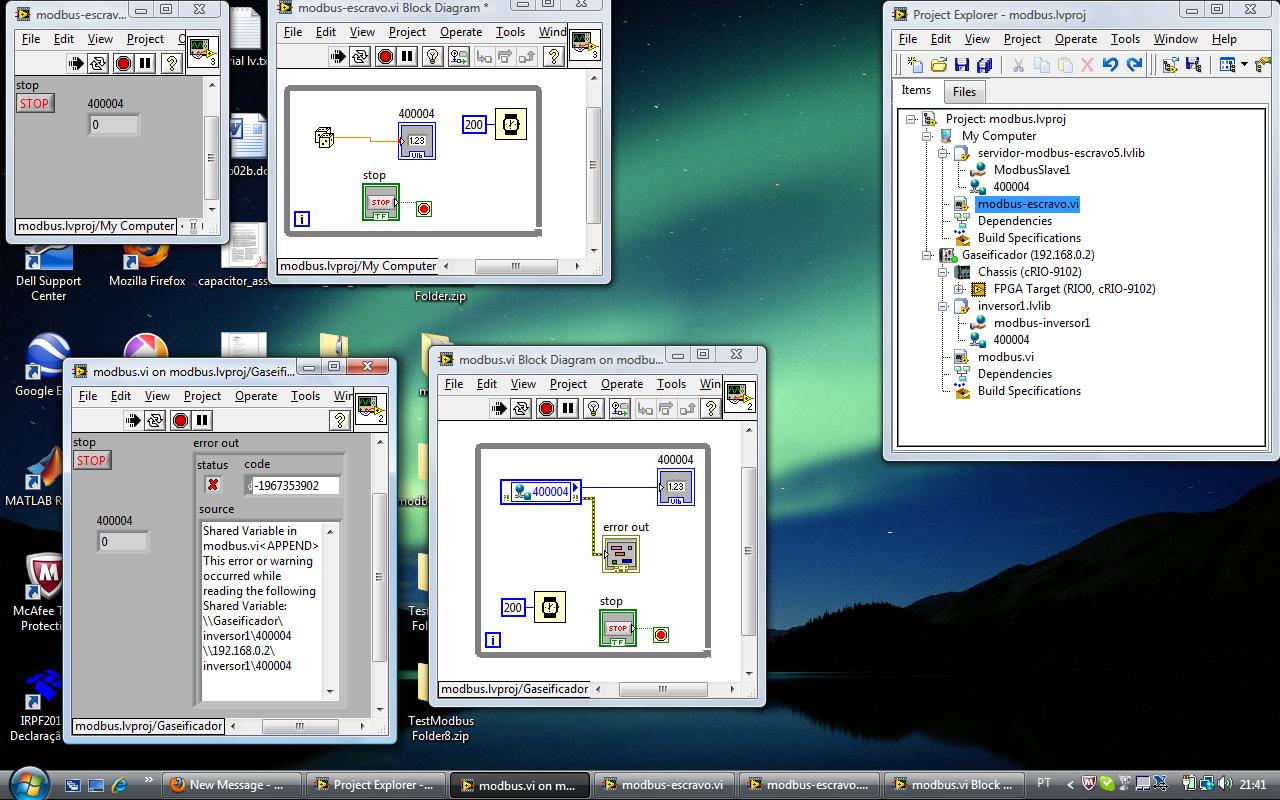
I'm programming an application LabView 8.5 and I need to communicate to a temperature controller Watlow via Modbus TCP.
The controller uses 32-bit floating point.
I know how to read two consecutive 16-bit registers to obtain a 32-bit word.
My problem is that the addressing of the Watlow structure begins to register 400,000 and Monte from there.
The NI Modbus Library (that I used on previous applications with different controllers Watlow) seems to support only 16-bit addresses.
I can't enter the registry values higher than 65,535 for my reads and writes.
How to read the registry values for the 'high-address' in the Watlow controller?
4 to 40 000 is assumed. You don't actually enter anything. If you look, for example, register 40 012, simply enter the number 11 as the address. (As in LabVIEW, addresses start at 0)
-
invertek modbus communication by car
Hi all
Seems modbus is a way to communicate with the disks for a long time. For me, and because we have a new machine equipped invertel drive P2 is new.
So, after many emails between invertek I couldn't so much as to communicate with the reader with their software. Only her entry to go to modbus.org
For their software, I use a converter usb rs485 and I use pins 4 and 5 (pc connection), but for modbus change for 7 and 8 (modbus)
Join is the manual for modbus for the driver.
My question is, what is the easiest to read VI (for now) of records and the way to the entrance. I need to input 03 (for reading), then the registration number?
Please help for the first step, then I'll build the complete software (I have now installed modbus library)
Thanks in advance
cpalka
-
Working with salvation by 422/485 baud rates
Hi all
I'm working with CVI 9.1 and I have 2 PCI cards:
Advantech PCI Serial port - RS232
FastCom Async PCI-335-RS-422 / 485
I know there are base lib com series which contains functions of RS232, I also know that these functions work well with 422 / 485.
My Question or problem is that I need to use the transmission speed of 6 M reflecting 50MH there is no option for a chosen this flow to the func rs232 baud, if I manually enter it'll work?
Or maybe there is a 422 / 485 lib?
Thank you
You need to set the clock FastCom Council at a non-standard frequency generator. The manual for the card explains how to do this using Windows API IOCTL function calls. There are also examples of programs on the CD supplied with the card.
-
With RW on PIX 525 SNMP community
I'm trying to configure SNMP on PIX 525 and Solarwinds use tool to download the config. When I try to download the config it tells me that the community string has read only rights. Y at - it give a way RW in PIX as in routers?
Thank you
Gilbert
For free, you can use Kiwi CatTools. You give names of username/password and it can connect to any Cisco device and upload the config. It can even create reports of diff on configs. Alternatively, you can provide a set of commands that you want to connect to devices provided and run it. It is in the same people doing the often preferred Kiwi Syslogd.
-
The use of two different NICs on the RT?
Hello world... I am currently working on a project where I have to deal with the problem mentioned in the thread topic: I have a PC with LabVIEW RT which must be able to establish network connections using two different network cards. One will be used to connect via TCP/IP to a host computer that will show you the data transmitted through variables shared; the other communicates with another PC via the Modbus Protocol. The key is that each communication is done through a separate network card.
So far I could not understand how to set up these two things happen. Does anyone know how to do this? Advice will help you.
For communication of RT, I use a project of RT standard, with the RT PC, given one of the IPs, and for the part of Modbus, I created a server I/O with a master and a slave. Separately, everything works fine, but when I get them together it does not work.
Thanks for your help!
Sorry it took me so long to answer, I've been busy lately... I found a solution to this problem that I mentioned, and just in case anyone has similar problems in the future, I will briefly describe what happened.
Caseyw suggested, he had to allow both NICs through the measurement and Automation Explorer. The cause of the failure of connections was in fact that I was not using the 'right' for Modbus communication, which was rolled out on the secondary card. The solution was to use the URL Protocol with the correct path in the field, addressing the right IP address. To avoid making this post a mixture of subjects, I do more futher, but I got the gist of it, so if someone has similar problems when I work with multiple network cards or Modbus communication protocols, do not hesitate to contact me, I'll be happy to help you.
Thank you
-
Watlow F4 HS USB GPIB communication problem
Hello
I'm trying to communicate with the Watlow F4 controller on a room of environmental Tenney. The only available is a GPIB port. I've successfully installed the GPIB-USB-HS cable and I can see this device under devices and interfaces MAX. However, no instrument find when scanning for default settings of the interface GPIB instruments. I also downloaded the Watlow F4 VI drivers and try to run away. I got a 1073807346 error occurred at VISA opened in Watlow F4.lvlib:Initialize.vi-> up.vi set Watlow F4 system
I use Labview 8.5.1 with 488.2, VISA, DAQmx installed.
Please see the pictures attached for more details. Any suggestions would be greatly appreciated.
Concerning
FliU
Try the VI is useless if the instrument is not detected by MAX. I suggest that refer you to the manual or the seller to see if there is something you need to do on the instrument for GPIB communication.
-
Communication RS-485 digital custom
Hi all
I have problem of RS-485 serial communication using NI VISA.
My problem is sometimes the data that must be read from the power Analyzer suddenly loss, if I skip this problem? so if data loss my program not the analysis of data from the power Analyzer, and then sometimes brutally data are raw (I think that error on read VISA) I can ignore it at?
I did many programs and still not working properly
Sorry for my bad English.
This is my video watch it please
https://www.dropbox.com/s/st6qs1cbtr72m0m/Bandicam%202014-05-05%2015-06-09-546.avi
Thank you ~.
-
Time clock real function communication RS-232 with Labwindows CVI 2009
Salvation OR,.
1st quarter > we at KPIT try to build a timer based LabWindows project as a system 'real time' that transmits a packet of 80 RS-232 bytes to an ecu each 10msec. With our current PC RS-232 communication port configuration (115200bps, 1Stop, no parity, 8 Data Bits, no flow control) we are facing difficulties when trying to send this package with consistency. The timer to 10msec mechanism does not always follow a call to 10msec timer callback function. Is it possible, as part of the 2009 ICB, we can get close to 10msec periodicity (more less more than 1msec)? (some times the periodicity is scary and my clock works at 100msec instead of 10msec however it is observed intermittently, not continuously). My machine configuration is CPU 2 GHz, 1 GB Ram, Windows XP. Please adivse.
Q2 > in the future, we would like to update 4 stripcharts (with the answer of the ecu which is a 12-byte packet), a table that lists the 12 a bytes in each column and also write the package received in a file on the disk in the rest of the time between pitches to 10msec. Is this possible at all?
Kind regards
-Mowgli
Salvation OR,.
We at KPIT are grateful for the quick and accurate response. We have revised our project based on your inputs. We are pleased to announce that the timer is very well behaved for steps up to 10msec (more less jitter msec). We will now try to introduce a frequency appropriate for our GUI elements. Our project for your reference and final excel is attached. We hope that this data will help other users should they encounter a similar problem.
Kind regards
-Ashish
Maybe you are looking for
-
Your cloud what ID has been disabled message
While I was out today, buzzed my watch and I saw a message allegedly from Apple.com saying my I cloud ID had been disabled and I need to go to appleukwarning.co.uk and sign in. The site seems so real but knowing how it could be a scam I did not follo
-
When you browse my application management in the settings screen, that I fell on the app already download Swype. I think it's great that it was already on my phone, but I can't use it. How can I use it?
-
Why my pc no longer works as before, following a message received from MICROSOFT VISUAL ++ message is the following: "we are changed, an error etc..." of it is without doubt that they believed I was a business while I'm just an old lady of 68 years w
-
HOW TO UNBLOCK A BLOCKED HOTMAIL ID? Hello.. .my hotmail id has been blocked a few mails spam that was automatically sent to a lot of people... now I want this email to be unlocked... .i get the following message when I try to sogn to Your account ha
-
Error 25007 occurred during initialization Fusion.Setup could not load Fusion Load Library Shim0
Error initializing fusion 25007occured. Setup could not load fusion with LoadLibraryShim0.Error:0 x 80131702... I get this error so that install NET FRAMEWORK 2.0 windows XP 32-bit Sp3 please help me