the coefficients of autocorrelation
Dear
I have their whole labview VI embeded that implements gzuncompress()
its the correlation measure
Best regards

You can absolutely do. Use loops for the Sigma, and then the rest is arithmetic base. There are no on-board VI not pre-made to do, but it seems not difficult to implement (and you can turn it into a VI as well).
Julian R.
Technical sales engineer
National Instruments
Tags: NI Software
Similar Questions
-
How can I get the Coefficients of scaling for the Butterworth filter FPGA version
I am trying to program a FPGA application where I need to be able to change the cutoff frequency of the filter. I see that I can do a terminal for the coefficients of the filter on the VI express Butterworth filter, but how to generate the coefficients of different cut-off frequencies of filter? When I use the VI of Coefficients of Butterworth host-side small floating-point values rather than the large fixed point values I see on the side turns FPGAS.
Thank you
David R. Asher
Hi David,
8.5 or 8.6, there is an example of navigation that contains the Subvi design filter you need:
examples\R Series\FPGA Fundamentals\Analysis and Control\Filter and filter Butterworth Reconfigurable DC-RMS\Using-R - series.lvproj
In LabVIEW 2009, there is a new palette in my computer: Interface FPGA > scaling, with a new VI of Coefficients of Butterworth on this subject. Who will produce the coefficients quantified, you need in the format expected by the FPGA Butterworth filter.
Kind regards
Jim
-
Why can I get two different results from the same coefficients?
I get two different results of the evaluation of the polynomial function.
For the first, I get the coefficients of a polynomial function to adapt. I feed the coefficients of the function made the function Eval Poly and get the correct 12.8582 result when I evaluate 49940.
For the second, I create constant array of values that have been returned by the polynomial Fit function (I typed in). However, I get an incorrect result of - 120.7913 when I feed the constant table the function Eval Poly when I evauate 49940.
How this can happen when I use the same values in table?
A picture of what I explained is attached.
Hi Altran,
are you sure about using the 'same '?
You compare them? Do you have (at least) set them to 17 digits display properties?
Please attach a VI instead of an image...
-
Move the file in the folder of the same name in AppleScript
I had a problem with the script below. Basically, on the execution of the script, I want to create folders based on the name of the file and move the files in the files of autocorrelation. However, at the minute, that I'll have to choose the folder in which the script should run.
Folder to choose a folder
say application 'Finder '.
located fileList to the name of every file in Folder with name extension is "m4v".
end say
the value point text delimiters to ".".
Repeat with dittos in list of files
get each text element of dittos
masterFile defined in the point 1 of the result
say application 'Finder '.
create a new folder to Folder with properties {name: masterFile}
move (each file from the folder Folder whose name contains masterFile) will cause
end say
end Repeat
Ideally, I would like it to run automatically, but the folder is on an external hard drive. (\Volumes\Lacie\Movies). and I had problems to use the POSIX and 'alias' to properly re-create the path of the file desired.
Any help would be greatly appreciated. Thank you!
Hello
You can try something like the AppleScript script which is a simple shell script wrapper.
set d to (choose folder)'s POSIX path
do shell script "/bin/bash -s <<'EOF' - " & d's quoted form & " 2>&1
cd \"$1\" || exit
shopt -s nullglob
for f in *.m4v
do
    m=${f%.*}
    [[ -d $m ]] || mkdir -p \"$m\" || continue
    mq=$(sed 's/[^[:alnum:]]/\\\\&/g' <<< \"$m\")   # quote meta characters for regex
    find -E . -depth 1 -type f -iregex '.*/'\"$mq\"'.[[:alnum:]]+$' -print0 | xargs -0 -J% mv % \"$m\"
done
EOF"
For example, given that you choose/path/to/directory in the folder - source
Input state:
/path/to/directory/abc.m4v
/path/to/directory/abc.txt
/path/to/directory/abcd.m4v
/path/to/directory/abcd.txt
Status of the output:
/path/to/directory/abc/abc.m4v
/path/to/directory/abc/abc.txt
/path/to/directory/abcd/abcd.m4v
/path/to/directory/abcd/abcd.txt
Briefly tested under OS X 10.6.8 but no guarantee of any kind. Please make sure that you have a full backup of the original files and directories before you run this kind of script.
Good luck
H
-
Card data scope of device to the TDMS file buffer
How transfer brought data card device buffer to TDMS file directly bye passing buffers LabVIEW and Windows. In the same way as DAQmx configure logging (VI) do we have any function scope?
The API OR-SCOPE doesn't have the ability to record data acquired directly on the disc like the DAQmx API offers. All data must be retrieved from the on-board memory, which makes data transfer OR-SCOPE kernel driver via DMA, and a copy must then happen to transfer data from the space of the kernel in user space (LabVIEW), how it can be manipulated.
The main reason for this flow is because the calibration scale occurs in the NOR-SCOPE driver and not the material. So if you were to save data directly to the disk as DAQmx, he stock raw ADC codes, without correction calibrated. The API OR-SCOPE allows to recover the coefficients of scale if you want to apply them at a later date after extraction of the data from the hardware. To optimize flow of data applications, it is recommended.
The only exception to the logging directly on the disk would be the Oscilloscope Reconfigurable SMU-5171R. It is being implemented with LabVIEW FPGA firmware using the design of Instrument libraries, code is open for editing. With the open nature of this software stack, it is possible to implement "direct to TDMS" functionality with LabVIEW FPGA Read region node.
I hope this helps!
-Nathan
-
What is the effective resolution of the Council Usb6361 ADC
I used a USB-6361 with 16-bit ADC Board. I went to simulate an implementation of County ADC bit lower and I noticed that the data collected from the 6361 seem to be 16-bit resolution. Here is an example of a part of the waveform samples (of type Double), with 0-5V range:
1.0727841521285737 V
1.09002147857432474 V
With a range of 5V and a 16-bit ADC, the bits of LS should quantize to 5V/2 ^ 16 = 5V/65536
0.0000762939453125 V
None of these samples can be represented with 16-bit precision; There are fractions remaining bits.
example: 1.09002147857432474/5V * 2 ^ 16 = 14287.12952396...
is it's 16 - bit quantum and the beach was unipolar 5V I expect an integer result.
Now, it's pretty easy to requantify 16-bit data solved, but what gives with the raw data from the USB-6361?
Why is it not 16-bit quantified for the beach?
The data do not seem to be 16-bit quantified for 0 - 10V or +/-10V or the other.
Clues here?
Ben covered the series X bipolar ranges but there are other factors that lead to what you see:
X series applies calibration in the software and it affects the HW and the returned data. On the one hand, the X series exceeded 5%, details covered in the section HAVE tied Ben manual. Also, on the application of calibration of the USB-6361 actually uses a third order polynomial for scaling - the voltage at the scale that you read don't directly correspond to the widths of code. You can make an unadjusted DAQmx reading and get direct bit of CDA. You can get the coefficients of scaling with the Coefficients of the scale property to HAVE device. If all goes well in looking at these, you can get what you need the device.
Thank you
Andrew S.
-
Editing of data with the 'gaps' in
Hi all
This may seem like a simple problem but I was stuck for a short period. Basically, I have a set of data, see attachment, and I want to cut the tip and fit a polynomial on the left what.
I see two ways to cut in the Middle, by replacing a part of the table by NaNs (no plottable) or simply delete the offending section.
Neither seem to produce a new table that lends itself to mounting, I have attached my VI which can do both (a need for editing or a rewire to use..).
Any ideas?
Kind regards
David.
Altenbach says:
Use "polynomial evaluation" using the coefficients found to generate data for all x-values that you want.

Try this... (LV 2010)

-
Adjustment of the integral of a Gaussian
Hello
I have LabView 2013 I'm trying to curve adjusted using the non-linear curve Lev - Mar vi but are unsure how to proceed. From what I understand, you can create a user defined model in the string, but the help files only detail a the second order polynomial of the form a1 + a2 * x + a3 * x ^ 2.
I have the intensity of the reflection of the laser on a sample of data, and when the laser moves on the metal marker intensity increases. The metal marker has a beginning of knife edge and increase intensity moving on the marker shows Gaussian beam shape and intensity profile can be described using the integral of the Gaussian shape.
Sorry if this problem has been posted before, but I can't see it in the forums in general pretty average I can understand as a new user. I basically want to model defined by the user of the integral of a Gaussian type and feed my data in the form (x i) and give it me the coefficients I can take the center point as the tip of the marker position.
Thank you
Paul.
OK, I have a comment on the Code and comment on the data. First, the code. You use a 'chain of the formula', which means that you ask LabVIEW to claim that it is Matlab and can 'interpret' a channel to follow the instructions as you want. It would surprise me a lot if it worked, especially with something other than the simple polynomials. Since it is LabVIEW () and write a VI to calculate F(x, a) and explicitly put in the square root and the erf functions you need.
In looking at the data, I confess that I don't know what you're trying to mount. I see a number of pulses noisy square wave what-look-like in X and Y, there does not at the same time. I'm guessing that you are interested in fitting something in the transition - why not seek 'big first derivatives' and she (for example), find the middle between high and low? If you need more sophisticated features of fitting, you could at least narrow down the set of data that you send to your function of fitting to include a small subset of points surrounding the transition.
Bob Schor
-
Automatic calibration of the 6024E Daqcard
I find that I can to calibrate the Daqcard 6024E with NOR-DAQmx. Is this still valid calibration when I select then "traditional configuration NIDAQ?
I'm sure that the automatic calibration using the coefficients that are stored on the card. Therefore, it should stick.
I would still recommend sending out for professional calibration once a year to ensure that the integrated standard is always good.
-
What does the argument [] State_Information in the FIRFiltering() function?
I'm writing a digital filtering code, but I have no experience with digital filters. I think I need the advanced analysis library FIRFiltering() function. This feature provides arguments for the input data table, all of the coefficients of the filter, the output array and also a table called the State_Information. Whence this table and what is it?
Original terms of X contains the most recent entries. The last entry prior should be the last item in the array. The number of elements in this array must be less than the number of items in the table of Coefficients of FIR.
-
Is it possible to filter design on FPGA reconfigurable on the fly?
Hello world
I wonder if it is possible to design multi-channel filters on the FPGA reconfigurable on the fly? For example, it is possible to have X bandpass filters in an iteration, and Bandpass Filters Y with different specifications in the iteration following without having to recompile the FPGA code? Is there a simple way to achieve such a purpose?
I have built such flexibility in the OTR (where each iteration has different filter settings) but hope to implement on the FPGA so.
If someone could provide ideas as to whether or not such a conception is possible, it would be greatly appreciated.
Thank you in advance for your help!
Steven
Hi Steven,
How do you try to generate the FPGA code for this filter, you are using the IP generator?
If so, this knowledge base article describes fixing the coefficients for multichannel to change on the fly filters. There is also a nice example in there also.
Also, if you use this IP generator, this help document describes the more Options box that has the ability to change the coefficients to be 'rechargeable' so that you can change these on the fly it too.
-
Coefficients of FIR (Hamming window)
Dear Sir/Madam,
I'm evaluating a simple convolution filter (low pass filter), to produce the coefficients to be used for the signal FIR filtering on the ARM microcontroller.
I used two different softwares to design an appropriate filter:
1 Labview (digital filter design)
2 Matlab (Signal Processing Toolbox)
I'm confused, because the coefficients of the result are not the same (the image attached below). (100% sure) Matlab and Labview (not 100% sure) use nomalized frequency as input for the design. The normalized frequency is:
FN = fcutoff / fsampling;
I tested in Labview on some signals with different fcutoff and fsampling, BUT with the same normalized frequency and the result was always the same (so I guess that Labview uses the normalized frequency also).
The filter settings:
FN = 0.2
type = low pass
= Hamming window
filter order = 24
ntaps/coefficients = 25 (filter order + 1)
The result:
It seems that the filters are not of the same order - the width of the main lobe is lower in the Labview example, and the height of the lateral lobe is larger. To my knowledge this suggest that the order of the filter is greater than one in Matlab. But both filters produce the same number of coefficients...
LabVIEW 'code' (only the coefficients of the numerator, since it is not a recursive filter):
and the code corresponding MATLAB:
coeffML = fir1 (24,0.2);
Anyone know the reason for this? Or I'm just a stupid mistake?
Thank you and best regards,
K
Greetings Alain,
I had a look at your problem and found a short explanation. The difference is how can you understand the frequency standard and how Matlab.
You can normalize the frequency by fs or frequency of nyquist (fs/2 as Matlab does). That is why your result for LV is different because you
expext standardization by fs.
Details can be found here:
http://www.MathWorks.com/help/signal/ref/fir1.html
"Wn is a number between 0 and 1, where 1 corresponds to the Nyquist frequency.
http://en.Wikipedia.org/wiki/Normalized_frequency _ (digital_signal_processing)
"Some programs (such as MATLAB) that the design of filters with coefficients of real value using the Nyquist frequency (
 )" as the normalization constant".
To solve your problem, whenever you want to compare results Matlab of the coefficients of FIR with LV filters, you must multiply the fs in BT by 2 before standardization.
I have also attached example program with comparison where the default values are calculated according to the above recommendation.
Have a nice weekend.
-
algorithm to find the top of the parabola
Use case: mower rejection of common-mode using a programmable potentiometer
Problem: The performance of each circuit varies greatly and you are looking for best value (lowest CMRR) gives erroneous results. The performance seems to be relatively flat on some circuits, straight on others. Launching in the middle range of the potentiometer and moving upwards or downwards, I compare the measured value after the change of the potentiometer to the last measured value. By doing this I can get for the lowest CMR.
Setup: entry wave sign 5V 60 Hz on both positive and negative of a differential ADC. The potentiometer is cut and reduces common-mode noise. Go away and the common-mode noise increases.
Question: I would like to use adjustment curve to calculate the shape of the performance of the CMR. Take several steps (no more than 10 then I hope). Get the x y (x = 0 to 1023 trim adjustment potentiometers, Y = amplitude of the measured signal common-mode). Find the vertex.
Is this possible and can someone point to an example. I have not found one.
A parable is a second order polynomial curve. The Summit must be the peak value. The general polynomial Fit.vi to maintain your data. The Coefficients of the polynomial outputs to calculate the location of the tip with a DAB of analytic geometry.
Edit: Note that you may need to do checks to make sure that your data has not generated any curve as a parable.
Lynn
-
How to find the frequency bands of the TPL for Wavelet db04?
The President complied,
I'm doing project on the simulation of the EEG signal, processing and analysis. I want to find the frequency of the signal band after having extracted the detail and the approximate coefficient. Here I used a Wavelet analysis (db04). I'll be gratfull for you if you can help me in this matter.
Thanking you.
Hello
You can use WA Wavelet Filter.vi to obtain the coefficients of the filter used in Wavelet transformation, then you might anlayze the frequency responses.
Thank you!
ZJ Gu
-
Help with the Calibration of MAX inside a VI
Hello
If anyone knows NEITHER MAX, I could use some help on this one.
I have a pretty basic VI to register and export data to TDMS files. This part works fine.
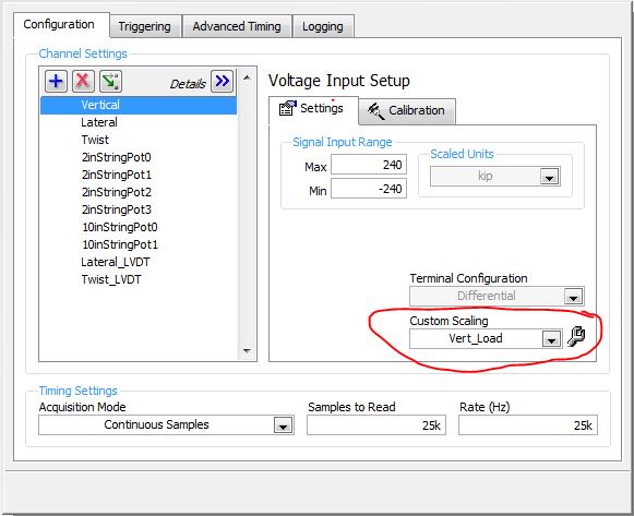
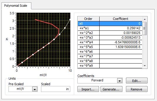
What I have a problem with is a second feature, the user wants to have at their disposal. They want to be able to see the coefficients in a polynomial calibration when the VI is on so that they can ensure that the calibration is up-to-date. Even more useful would be an indicator when the unit has been calibrated, but it is secondary. The problem is that the calibration is in this case made in the custom game scale of MAX, as shown below in a few screenshots.
↑ This is information I want displayed on my front of LabVIEW.
Thank you!
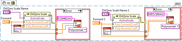
Thank you, but I try not to use MAX here. I want a standalone VI which sets the coefficients of the scale of this show. I thought in fact most of it it out on mine. Here's what I have:
He tries to define the coefficients of an existing scale and creates one if the scale does not already exist.


Maybe you are looking for
-
Re: Can not find the latest version of the BIOS for my Satellite A300 - 1 2
Hello world I'm looking for the latest BIOS for my living room Satellite A300 - 1 g 2 (PSAGGE) I can't find any BIOS to the dl page.Maybe someone is able to help me. See you soon,.ezsolt
-
Drive CD of Satellite Pro A200 is not digitally signed?
I can't use the CD drive on my laptop, Device Manager displays a yellow triangle with an exclamation mark inside. I updated the driver but it still does not load and I get a message from Device Manager: Windows cannot load the driver for this hardwar
-
Vista and all applications of Toshiba on the recovery disk?
Hello everyone I have problem with recovery disk on my laptop.When I had formatted my HDD I lost my recovery and I can't return it.That is why I need order of Toshiba backup recovery, but I have a question about it. Could you please give me some info
-
Satellite A30-104: WLan not available - I turn on the wireless network card
I have a Toshiba Satellite A30-104 with an inprocomm ipn2220 built in wireless card. The problem I'm having is that when I get a network says its not available and asks me to turn it on. The driver is installed for the card, the switch for the wirele
-
Display color on a rectangular column data
Hi all I am currently using a RGB sensor to detect painting on plexiglass. The RGB sensor is mounted on a robotic arm and detection performs a vertical movement using the robotic arm. Each movement covers an area rectangular 110mmx70mm. The value of