the continuous reserve and the sticky timer
Hello
Imagine the following configuration:
Sticky ip-netmask 255.255.255.255 address source stick_serverfarm_A
Timeout 10
Serverfarm serverfarm_A
Serverfarm host serverfarm_A
Book server1
development
Book Server2
This standby
the continuing standby command performs the following:
Tears down connections existing non TCP on the server
Allows current TCP connections complete
Allows new sticky connections to existing server connections that match the entries in the database in post-its
Balance the load all new (other than the above sticky corresponding connections) connections to other servers in the farm
Finally takes the server down
I have a question for "Allows new sticky connections to existing server connections that match the entries in the sticky database".
Connections that match an entry in the sticky database sticking them to server2 will be delivered to server2.
What happens with the meter of "time-to-expire? The time-out value for the entry of post-it on the server "continuous standby" will be reset and restart with the configured time-out value?
I find no answer in the documentation for this issue. If the counter is reset even when the book is development in standby, then it is possible the book will ever 'empty '... (especially when the value of timeout is for example 24 hours)
Kind regards
Jeroen
ACE10
A2 (2.4) version [3.0 (0) A2 (2.4) of generation]
Hi Joroen,
Please find below a short test I've done in my lab.
switch / Kanwal # sh sticky base
Sticky group: STICKY_SFARM
type: intellectual property
Timeout: timeout of 60-activeconns: TRUE
flags of time expires sticky-entry book-Forum
---------------------+--------------------------------+--------------+-------+
64.103.236.75 A:0 3579-
Total inflows of post-its: 1
As you can see above the sticky entry is with Server A and below you can see decrease in value of the counter.
switch / Kanwal # sh sticky base
Sticky group: STICKY_SFARMtype: IP
Timeout: timeout of 60-activeconns: TRUE
flags of time expires sticky-entry book-Forum
---------------------+--------------------------------+--------------+-------+
64.103.236.75 A:0 3559-
Total inflows of post-its: 1
switch / Kanwal # sh sticky base
Sticky group: STICKY_SFARM
type: intellectual property
Timeout: timeout of 60-activeconns: TRUE
flags of time expires sticky-entry book-Forum
---------------------+--------------------------------+--------------+-------+
64.103.236.75 A:0 3558-
Total inflows of post-its: 1
switch / Kanwal # sh sticky base
Sticky group: STICKY_SFARM
type: intellectual property
Timeout: timeout of 60-activeconns: TRUE
flags of time expires sticky-entry book-Forum
---------------------+--------------------------------+--------------+-------+
64.103.236.75 A:0 3556-
Total inflows of post-its: 1
switch / Kanwal # conf t
Enter configuration commands, one per line. End with CNTL/Z.
switch/Kanwal (config) # do sh running-config serverfarm
Building configuration...
Host A Serverfarm
Book A
development
Book G
development
switch/Kanwal (config) # A serverfarm
switch/Kanwal(config-sfarm-host) # book has
switch/Kanwal(config-sfarm-host-rs) # Eve continues
output switch/Kanwal (config) #.
I put the server in standby mode and below you can see the meter continued to decline.
switch / Kanwal # sh sticky base
Sticky group: STICKY_SFARM
type: intellectual property
Timeout: timeout of 60-activeconns: TRUE
flags of time expires sticky-entry book-Forum
---------------------+--------------------------------+--------------+-------+
64.103.236.75 A:0 3504-
Total inflows of post-its: 1
switch / Kanwal # sh sticky base
Sticky group: STICKY_SFARM
type: intellectual property
Timeout: timeout of 60-activeconns: TRUE
flags of time expires sticky-entry book-Forum
---------------------+--------------------------------+--------------+-------+
64.103.236.75 A:0 3502-
Total inflows of post-its: 1
switch / Kanwal # sh sticky base
Sticky group: STICKY_SFARM
type: intellectual property
Timeout: timeout of 60-activeconns: TRUE
flags of time expires sticky-entry book-Forum
---------------------+--------------------------------+--------------+-------+
64.103.236.75 A:0 3501-
Total inflows of post-its: 1
switch / Kanwal # sh sticky base
Sticky group: STICKY_SFARM
type: intellectual property
Timeout: timeout of 60-activeconns: TRUE
flags of time expires sticky-entry book-Forum
---------------------+--------------------------------+--------------+-------+
64.103.236.75 A:0 3500-
Total inflows of post-its: 1
Then I refreshed the page and you can see that the value has been reset.
switch / Kanwal # sh sticky base
Sticky group: STICKY_SFARM
type: intellectual property
Timeout: timeout of 60-activeconns: TRUE
flags of time expires sticky-entry book-Forum
---------------------+--------------------------------+--------------+-------+
64.103.236.75 A:0 3592-
Total inflows of post-its: 1
Therefore, reset the value of time to expire and start over, even if the server is in standby mode. I hope that answers your question. I would like, if you have any questions.
Kind regards
Kanwal
Tags: Cisco DataCenter
Similar Questions
-
I bought an iPad 2 Air and reserved for a free service call to show me the ropes. Nobody phoned me in the allotted time. What should I do?
Click on the help link at the top of the page and connect with Apple
Or you are welcome to ask us your questions
-
Cloud of continually closes, and closes all the fonts I have loaded? I have to log in several times a day, someone knows why?
Please follow:
-
Continuous 5V output and signal of Stimulation at the same time
Hello
I'm out a constant signal to 5V to power a testbed and output a signal of stimulation (create a small magnetic field, etc.) at the same time. I try to use DAQassistant with several output channels, but I can't fix an AO0 data set and the other set of data in AO1. Please notify; my code is up to this home.
Thank you!
Emily
Many DAQ cards provides a constant voltage of + 5V output. DAQ hardware do you use, and there a such output? If so, use instead. It will manage a current higher than an analog output. The analog output lines are not designed to power no matter what, they are purely for signalling.
-
HP Jet 7: Using devices on a compressed Windows all at the same time continue to load
Hello
I have a windows Tablet 7 flow HP (model 5701).
I would use it for video-conferencing using a USB ethernet port and a USB camera.
Is it possible to connect these devices to the Tablet via a USB hub, and at the same time continue to charge the Tablet?
I have looked everywhere for information on how to do it, but have not been able to get a clear answer. I have, it is possible, what kind of hub should I buy?
Thank you
Edgard
Yes, the Plugable Pro8 works for that and there are other solutions mentioned in this thread.
-
USBOTG and Charge at the same time on Stream 8
To keep this thread as productive as possible and efficient for those who find it useful to:
Unless you have under your eyes
1. a schematic representation of the 8 Stream USB port (USB port and battery electric circuit etc.)
2 source code for the firmware BIOS and kernel that controls the material
Please DO NOT respond or say "is not possible". In view of the above is true, you do not have enough information to say '' not possible. ''
If no one replys with a solution, what he calls not possible by default.
Also please do not answer to say ' I don't know how "or" but I know how to do anything else that ' is also not that useful.
An update of the BIOS or other software update may be required by HP, Microsoft or both to offer this feature really intuitive and quite possible.
And I hope that this thread can be an effort consolidated by all who have the 8 flow to make the necessary changes. The majority of the other tablet PCs are capable of it. It seems that only the 8 Stream and a few others have trouble with her.
~~~~
I want the ability to use a simple, inexpensive cable and perhaps standard (with electronic active minimum inside) which allows me to host and to use one or more USB devices on the Stream via its USB port B microphone 8 while this cable can also be connected to a charger standard and charge 8 flow simultaneously. This means that the cable has a minimum of three connectors. One of the possible configurations are as follows (apart from the normal charging cable):
1 cable Micro USB B Male - connect to the stream 8
2 USB male A - connect to the AC charger (IE one that came with the 8 Stream)
3. USB A female - one or several connectors to plug into the key of USB data, keyboard, mouse or even a hub.
Connector # 2. above shall provide a power supply to recharge the 8 Stream via conn. #1 and the power supply for external USB devices via conn. #3 so that they are in use - all at the same time.
A and if the same cable can act as a normal OTG no charger for when no external power supply is available. This may necessitate a switch or an electrontics active inside.
The last part of this goal is unimportant for various reasons. I wish that HP, the manufacturer of 8 flow, to State in writing good mode necessary to do this, so that other manufacturers or even-it yourself can make maximum use of their tablet HP equipment.
~~~~
The neat thing it will alow a person to do with their tablet, it is to work at home using the Tablet as a desktop PC by connecting a keyboard, mouse, perhaps external screen (with USB to the display adapter) and knit for a long time without time limit prescribed by the battery life because the charger provides energy to all involved.
If there is only a single connector on the cable #3, then an additional node of coarse had to provide support for these multiple USB devices at the same time. However, it would be better if there were several #3 connectors integrated in the cable itself. This would be better as a suitable USB hub also requires its own power. That an adapter is necessary if the whole thing were integrated into one.
~~~~
I really want answers from anyone who has already accomplished USB OTG delivered with simultaneous load with flow 8. (independent of any published 'proper' way is also welcome)
Today's date is 2015-01-16. If in 2015-02-16 (one month), nobody has posted a solution and then starts to bug HP and Microsoft on it's us?
~~~~
Technical training:
I understand the possibility the tablet software and firmware must take a decision on the manner in which power flows on the power port USB microphone B pins.
I know that with a proper design of the electronic circuit carring these signals of power inside the Tablet could be sensitive to what is connected and without risk to decide for himself what to do without needing to control software. For example by testing/detecting periodically differential voltage or current management to see what sides of the connector can supply.
But this is only one of the many "could bes".
In addition, this can be no standard regarding the standard USB. What seems to be actually the case with a lot of cables OTG + fresh, is that physical clues embedded in the cable or charger are used to signal to the Tablet what the situation is. Then the signal of software/firmware of the Tablet, interprets what the situation is intelligently and responds by flipping the bits of correct hardware control to activate, or deactivate the power flow in the port and also control its direction in or out.
I'm not familiar with the standard USB. Maybe I could do more research, if I believed that HP followed with 8 Stream or even the standard covered this situation explicitly.
But to a certain extent, it seems I'll have to invent something that should be intuitively just like it does with other tablets. Isn't it? Maybe I'm overthinking, but I can't find any USB OTG + cables load that specify compatibility with 8 HP flow.
In any case, I was familiar with both methods other use of tablets to send the highest mentioned signal to the hardware/firmware/software of the tablet to the idea that it's time to load / time of OTG or both.
The first method is a 0 Ohm to 200 ohms short between pin USB A 2 and 3. This is the bidirectional data differential lines D - and D + respectively. In data mode, all the data passes back and forth on those lines. When you load with a cable, it's the charger module that puts this short, not on the cable. I measured the short on three different Chargers. It is 0 Ohms on two of them, one of those who are the charger that came with the 8 HP flow. The others 0 ohms was generic. The third was for an apple iPad and it measured on 53KOhms. It's probably not the resistance ohms 0-200, but probably it is impedance termination indicating that there is some intelligent serial port communication in the charger itself. Leave it to Apple to be different.
This method is somewhat questionable, as this signaling mode would prevent OTG + fee because it seems unlikely that you will be able to OTG when the data lines are shorted each and overloaded with such low impedance. I could be wrong on this subject...
The other method I have seen suggested to work with some tablets and phones other than the 8 stream is too short the USB microphone B pin 5 to Terminal 4 with 0 Ohms to 100 000 Ohms.
USB B has 5 pins. USB has only 4. The extra pin on B moves the GND pin 4 pin 5 pin to and makes pin 4 PIN ID.
If this signal applies to a drop in the ID pin (4) or in some cases, I saw that she proposed, he runs down with 0 Ohms.
Dead shorting things always makes me nervous. If ID is a simple normally high impedance high input, resistance could be used to make voltage well below the low or zero threshold while also preventing the risk of damage when cheat on him with a device that you do not have the diagram for.
Yet, 100K is a bit high for a 'pull down' in most of the situations that I'm used to. Even a 10K would be uncertain. A 1 K or 2 K seems reliable enough, but then things are weaker and in know more nowadays low... All but a dead short but if possible.
So, it seems possible that the device might be able to "indicate" by the specific value of the resistance, which can be found here. In other words the resistance is not a pull down but in fact a signature analog ID, in which case the exact value will be crucial. So if this is the case, a guess is not going to work.
Obviously in such a system as described above, a chip inside the Stream 8 should be responsible to support this information. I hope the 8 Stream has such a chip.
Probably a register inside this chip would be at all times what the State of the pin ID is a binary number. All that is needed is for the BIOS to the chip and the registry in it and read this number via the bus to determine what happens to the port. Finally, he would use that signals of info to send the order of material to the electrontics of power set the appropriate direction to take etc. (and change the State of the icon on the screen of the rude)
I don't know if the PIN ID method described is a standard USB or not either.
Eventually, there may be a third way. But I do not suspect that it would be possible with a non-active external device. In any case too complicated for the novice DIY for sure.
The device would need to act is a kind of extension of bus. As an active hub. But she would use the negotiation of data USB serial lines and in addition to reproduce one or more additional USB ports, intelligently inform the tablet to get with the program which is "now we're going to otg and recharge at the same time."
This requires a smart external device with a processor Inside, no doubt.
It seems to me that many other tablets have been able achieve avecjoint here the need for a smart external device and thus the flow must also be able to do.
There is a device that claims to be able to work with the HP Jet 7 and 8 and provides same ethernet and USB and big DVI ports so loads the data stream. But its expensive because it is active. Se here:
It's called a "Docking Station".
A reference to a product that does exactly what I want (possibly without active electronic components) is here:
It's by Kirin and it is a device of type squid with four USB ports. Precisely, which is my goal. But read in the comments stream 7 user indicated that he would not be OTG and load, not really clear if it worked as a hub USB OTG or not. Another evaluator stated that she would not support even a single USB device much less fees of 8 Stream. This device has a switch.
I forgot to mention that some 'hackers' have claimed success with other tablets to deceive their devices by using a multi-step process to plug things in. Usually in general they would get connected Tablet and load first, then they would return a switch or something remove some resistance or the signal was introduced by the first position of the switch. For some reason any Tablet would continue to require. Then the data lines would be free and they would plug in a usb key and it mounts correctly even if the tablet was always in charge.
It's like the power circuit has a lock which does not allow it to return to the mode "power flow" as long as he still feels the power flows inward regardless of what software it is telling. Full proposal here.
These tips seem dubious to me. Changes in the BIOS could change the way it works. Also you can not be sure what actually happens if you do not have a schematic representation. You could damage your tablet. Many people will support icon in the operating system whether the Tablet is in charge. But I'm sort of a low-risk guy and my policy is generally indicators of intereperet not to have meaning at all once a device is functioning in a non-standard setting. Especially when it's something that I did not built and could not fix if I FRY.
Hypothetical reasoning: tell me what data sensory discs really the State of the charging light screen? This reflect the bit of hardware control programs actually feeding management and status on the port? Or does it measure the direction of the flow of power, said in the section of the circuit battery monitoring? Point - none of us have a schema because it's owner. To really be sure according to the smart electronic hardware, the port must be mode flow under advisement "of power. If it's in a "power flow out" mode and power will be delivered externally as well you wind upward with both power supplies the same power at the wheel nets. In this case, the two opposing regulators attempting both to drive 5 V can have slightly different voltage calibrations. That could lead to fighting between them, with more than 100% of their capacity. For example if you try to regulate 4.95 real V and the other and other attempts to regulate 5.05 V. Current then flows to the tune of 100 mV / a few milliohms in the cables linking the two. This may be several amperes. (many) In other words, like I said: you want the tablet to know that power is coming in don't go out and automatically hitting the internal switches needed for that to happen. Probably the icon should indicate this with precision, but in some wacky situation, he could not. There may be a chance that the icon could indicate the load and still be burning or focusing on some circuits of the tablet or the charger.
Another thing, I could see that happening is if you play with these reported resistance types enough you might find a resistance value that winds up place the device in an intermittent condition. In other words it keeps flipping back and forth quickly between OTG and fresh. It can give the illusion that it works. You can have marginal communication with your USB devices and battery could even load. But will still be a lot of stress on the power circuit.
It is difficult for me to risk a Tablet perfectly well if I don't know exactly what I'm doing.
If a brave individual makes their own experimentation and verifies that it charges and OTGs and you tell the rest of us, you're a hero.
Maybe one of you has a good knowledge on the USB standard to have more confidence in such an experience... like what the ID pin 4 REALLY supposed to work for example?
That's what I know so far. If you think you can help, thanks in advance, or if this helped you, then your quite welcome.
It works
Evidence
http://targusblog.com/2014/11/25/how-to-turn-a-99-Tablet-into-a-workstation/
But it's 4 x the price in Europe
Have fun
-
Questions about serial port read and write at the same time
Hi I create a user interface for the communication serial port, where there are essentially 2 front panels, where the user enters commands one and the other where the prints of UART is delivered. I thought initially using a state machine but the reading and writing may be independent sometimes and so I can't rely on States. I searched a bit on the forum and he left me even more confused. Help, please.
(1) in a thread that sessions visa duplicated has been used for writing and reading at the same time, is it recommendable? How will this affect performance?
(2) essentially when the vi is reading data are it must constantly view as well, however, someone said that it takes too much memory to use shift registers, so how do I go about this? If using a State in queue after the loop of reading it affects the playback loop and be sequential?
In addition anyway is to move the cursor to the latest data from the indicator
(3) for the control of the user input, assumes that the user has entered an order in the control and press ENTER, then writing visa is launched, but if it comes in another string and press enter then write must be called again... is - it possible? will detect the previous commands in the control of compensation?
(4) according to my understand the expectation for the event do not monopolize resources and writing can go in parallel, am I right?
Thank you. I have attached a very basic vi which took me to the point, but I want to make it more robust. Please help especially in the part of the user interface.
su_a,
(1) you can have only one session to a port. Several UART can handle full duplex so performance is not affected. At flow rates of high data and large amounts of data, buffering and latencies of BONE can become a problem.
(2) who told you that shift registers using too much memory? Shift registers are usually the best way to transfer data from one iteration to another. String concatenation inside a loop (registry to offset or not) causes the chain to develop and may require re-allocation of memory. Your VI never clears the string so its cold length become very large.
Generally, you do not have an active cursor on an indicator. If you want to always display the most recently received characters and turn on the vertical scroll bar use a property node to keep scrolls to the bottom. This can be annoying for users if they attempt to manually move the scroll bar and find that the program continues to move it back automatically.
(3) if the user has changed the value in the chain of command, when he hits enter the modified value event fires. Simply strike brace does not change the value and does not trigger the event. Not control need to be erased, but the value that he has to change. If you want to send the same command again, have a button send a command may be a better choice.
(4) write is a case of the event. It is not in parallel with anything. The structure of the event do not monopolize resources. The other loop will run while it waits.
The event loop will not stop when you press the STOP button. Probably it wll take two command: change events of value after JUDGMENT before any loop stops. Replace the Timeout event (which never expires) with a STOP: value change event and a real wire of this judgment to the Terminal endpoint. Remove the local variable. Make mechanical locking when released.
Lynn
-
Why can't acquire data from strain and resistance at the same time with a NI 9219 module?
Hello
I use a chassis with a NI9219 module 9172 cDAQ to try to acquire the strain and resistance at the same time, with the Labview SignalExpress software. Is this possible? When I try to display two values of signal at the same time, I get an error of assistant DAQ 50103 'the specified resource is reserved. The operation could not be performed as indicated. I used to be able to acquire the strain and tension at the same time, but now even that gives me error 50103. I have hours trying to figure this out. Any help would be greatly appreciated.
Thank you
Justin
That's all! Thank you very much, now I can sleep tonight - seriously!
Thanks again,
Justin
-
NEITHER 9207 reading current and voltage at the same time channels
I have a cDAQ-9178 chassis USB-three cards NI 9217 RTD, three cards 9263 0 - 10V and one the output OR 9207 16 channels analog card. What I m trying with this kind of things, is to read all the analog input channels (information of transducer, temperature, pressure, etc.) and adjust my controls to process with the analog output channels.
My problem at the moment is the following:
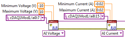
When I create tasks with DAQmx VI:s, how to create a task that reads current and voltage on the 9207 channels at the same time?
When I created a task for RTD-channels (16), a task for the outputs analog 0 - 10V (12), a task for the analog input 4-20mA (8) and a single task analog 0 - 10V input (8) I get an error-50103. I think it s because the tasks of current entry and voltagge are trying to use the same CAD at the same time and LabVIEW informs that "The specified resource is reserved. Tasks are to leave so that the analog output task starts first, then I merged all clusters of the error and the rest of the task are started by an order to current input-> input-> RTD input voltage. I get this error after the current enter task started and enter voltage task begins.
Because I m new on the LabVIEW and stuck in that time, I wanted to try the forum to find answers. I tried to find if someone else was having the same kind of problem, but with a quick search, there was none. I m in a bit of hurry, so I apologize if West a subject with a happy for that and I missed too much according to me.
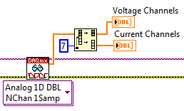
Really, the best way to do it is just adding 8 channels of voltage at a task, then 8-channel current, somewhat like this:
Then spread over different channels when you read later:
It should run without error. It always is multiplexed to sampling, but it will be much faster to create two separate tasks. There will be between 2ms (mode high speed) and 52ms (mode high resolution) between each playback channels, but it will still be much faster than the permutation of the tasks.
-
How to create impulses cause a pulse width Variable AND at the same time
Hi all
I have a NI PCI-6251 that comes with 2 counters, a FREQOUT port and then some DIO, DAC and ADC. I want to trigger a pulse of variable width (easy to do with two counters) and a frequency closed, exit at the same time. So, I want to end up with a line that will display TOP for some variable time, while the other exits a train of pulses for a time variable. It is easy to do if you have 4 counters but I don't have one. Does anyone have an idea to implement these two things AND making them trigger at the same time with the PCI-6251 card?
The line is high for as long as your pulse train controlled?
If so, set up the first counter as output pulse, configure the 2nd as output continuous meter but with the internal of the first counter output as its trigger to pause (pause when it is low). Start the 2nd meter before the first.
If not, you will need to use the digital output to replace at least one of the counters (max sampling rate is 10 MHz, so this would give less resolution compared to the time base of 80 MHz counters). So you would simply write the waveform predetermined in the buffer and he clock at the desired rate and the number of samples to give the signal that you want. You need to generate some other subsystem as FreqOut clock.
Best regards
-
Hello!
My problem appeared when I tried to update my traditional NOR-DAQ legacy code to DAQmx.
I use 2 meter (meter 5 and 7 meter) on PCI-6602, to generate trains of pulses, as well as the lines of e/s digital port 0 (the form lines from 0 to 7). What I do in my request, it's that I'm starting to generate the pulse train on the output of 2 meters and after that I play with the State of digital lines.
Traditional, it was no problem to use the meters and digital lines at the same time, everything went perfectly, but in DAQmx, is not possible.
What's happening: I start generating train of pulses on the output of counters, no errors, but when I try to change the State of a line of digital port the generation of the pulse train is stopped. What happens when I start the task associated with the digital way.
My question is: is it possible to create a channel on digital lines without changing the channels created for meters?
Another thing that I managed to do with the panels 'Measurement and Automation Explorer' and Test for PCI-6602, is basically the same thing, I generate trains of pulses on the output of the 7 meter and try to start a job on the digital line, but I get an error:
"Error-200022 occurred in test Panel.
Possible reasons:
Measurements: Resource requested by this task has already been reserved by another task.
Device: Dev4
"Terminal: PFI8.On the contrary if I use the counter 0 or a counter 1 to generate trains of pulses I encounter the same problem.
What resources are used by 2 to 7 of the PCI-6602 card counters and the counters to 0 and 1 do not use?
Thanks in advance for any answer!
Ciprian
After doing some real tests on this device, I found that it is a normal behavior for the jury of 6602. This is because when you start a task digital all 32 lines are configured for digital i/o, so it replaces your meter operation. The article below the link explains a little more on this subject. You must start the digital task before the task of counter to use the features of both in your program.
2 meter and above will not work correctly when you perform digital i/o on NI 6601 or 6602
http://digital.NI.com/public.nsf/allkb/43F71527765EEC3886256E93006CD00C?OpenDocument
-
Hello
I want to generate the continuous signal and at the same time I want to read that signal that I generate using a single card DAQ. I want to generate signal and the received signal is synchronized and in phase.
I looked at several samples on the sync, but it quiet confusing. One using the same clock of entry while the other use a trigger to start. I use the PCI-6024E DAQ card.
Can someone help me in this regard?
In two of these screenshots, the task to HAVE started first (that's what you want, because it is the task of the slave).
Typically for AO, you can simply write a unique period of your waveform, and then regenerate again and again. Your waveform would be preset before the task starts. If you need to update the waveform on the fly according to enter programming during execution of the task, you would disable the regeneration. In addition, if the wave form is such that it cannot be easily represented by a predefined buffer (for example, it is a strange frequency which is not a same ditch at the bottom of the sample clock), then non-regeneration is the way to go.
Best regards
-
Why the execution time increases with a while loop, but not with "run continuously?
Hi all
I have a problem of severe weather that I don't know how to fix it because I don't know exactly where it comes from.
I order two RF switches via a data acquisition card (NI USB-6008). One job at the same time can be selected on each switch. Basically, the VI created for this feature (by a colleague) resets all the outputs of acquisition data and active then those desired. It has three entrances, two chain simp0le controls and a cluster table, that contains the list of all the outputs and some practical information to know what is connected (specific to my application).
I use this VI in a complex application, and I have some problems with the execution time, which increased whenever I said the VI, so I did a test VI (TimeTesting.vi) to determine where the problem came. In this special VI I record the execution time in a csv file to analyze then with excel.
After several tries, I found that if I run this criterion VI with the while loop, execution on every cycle time increases, but if I remove the while loop and use the funtionnality "Continuous run", the execution time remains the same. In my high level application, I have while loops and events, and so the runtime increases too.
I someone could explain to me why execution time increases and how can we avoid this? I have attached my VI test and the necessary subVIs, as well as an image of a graph that shows the execution time with a while loop and «run permanently»
Thanks a lot for your help!
Your SetReset_DO VI creates a channel whenever it is called. And that you never delete a task.
When running continuously, that it's as if it only runs once and LabVIEW has internal mechanisms to close references that will not be used again. When a VI is used as a Subvi, LV does not know if she will be called again, and lacks these things until the first level VI stops. You have a memory leak.
Just as you open and close your file outside the loop for, create your channel out of the loop.
Lynn
-
Hello!
I noticed that the continuous measurement and a project in LabVIEW 2012 Logging using chains instead of enums and orders from the queue. I wonder if there is a good reason for it?
Kind regards
Anguel
First, string vs enum debate is probably the version of LabVIEW vim vs emacs. There are good arguments on both sides, and I doubt that there is always a "winner".
A brief summary of our reasoning for the current state of the project examples:
- We used enums for the state machine because it is self-contained. A state machine will never tell himself to enter a State, he does not know. Knowing (as the programmer) all possible States with the help of an enum allows you to enlist the compiler in order to help us avoid mistakes to change the time (because you can't quite out an enum and LabVIEW can be said if you are not covering all cases to a structure of the case, etc..).
Enums provide greater protection and rigidity by ensuring all withdrew at the time of publishing. This is often the 'default' recommendation that we do.
- We used strings for messages in queue manager because the producer of message and the message handler could be independent processes that are reused or traded. Channels avoid the need for the compiler to be able to connect the orders and push this responsibility to the programmer. This allows you to develop some sub-components independently as long as you agree to a series of channel commands that you can manage - you need not to share a file 'messages.ctl' or 'states.ctl '. It is conceivable a loop of message management a message it does not, how you can decide to either silently ignore it or will trigger an error (as we do in the model). The strings make it also easier if you want to swap the queues of LabVIEW outside by a TCP implementation for network vacilitate or intra-Processuse communication where the other end may or may not be written in LabVIEW.
Channels to provide more flexibility (that is, you can add new commands to an existing via plugins system, you can pass parameters as part of the string, etc.) at the expense of pushing her potential errors at run time and to put more responsibility on the programmer.
- The actor's gifts frame a 3rd option - using classes such as messages. For me, it combines many of the advantages of these two enumerations (strictly typed, change errors) and strings (flexible and scalable), but with the disadvantage of being somewhat less transparent (you understand OO, be comfortable to navigate through a multitude of screws, legacy of understanding, etc.).
I don't know there are other reasons, others to the breast OR had or seen as we validated models and examples of projects in-house, but here are my reasons. We know that we can not design for each situation there - our goal is to get useful models against new users to make them aware of what well thought LabVIEW programs are similar to experienced users know their applications better and I hope they do not hesitate to change what we provide or create their own designs, when they feel it's necessary. (On a side note, please share what you come up with - a community of experts sharing models would be really useful to us all LabVIEW users).
Best regards
Simon
- We used enums for the state machine because it is self-contained. A state machine will never tell himself to enter a State, he does not know. Knowing (as the programmer) all possible States with the help of an enum allows you to enlist the compiler in order to help us avoid mistakes to change the time (because you can't quite out an enum and LabVIEW can be said if you are not covering all cases to a structure of the case, etc..).
-
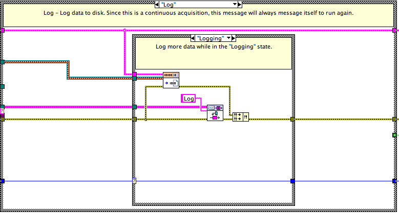
Continuous measurement and logging model - Hang-Up of may because of the lost output
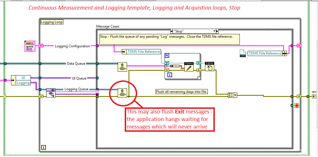
The model of continuous measurement and logging in LabVIEW 2012SP1 has a flaw in the Acquisition and recording loop.
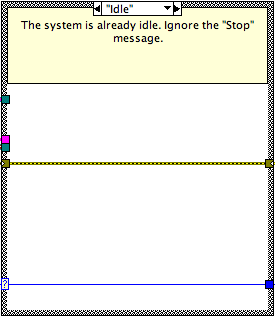
Stop messages manager ignores all messages in the queue of messages. The note says:
"Stop - empty the queue of all pending messages 'Connect'. Close the reference of TDMS files. "See the picture below.This concept breaks if the output message is issued while the Stop message is being processed. The time gap critical to do this is small, because the issue is posted on the front of the queue. But it depends on the treatment in the case of the Manager to stop. Large or small - it can happen.
The symptom is the application block in an infinite waiting on the queue of message - all commands have no effect, as the rest of the loops are completed. Break terminates the application. Pause button doesn't work anymore. (see this entry forum)
This problem may appear only after enforcement has become more complex and the schedule has changed - the fresco made model works and does not reveal the question.The cure: first of all I thought to preview the elements of the queue before they are scrapped selectively, one by one in the loop to stop, but that usually is not working either, because the output can happen precicely in the laps of time between overview and dequeue - don't forget no outputs are displayed on the front of the queue.
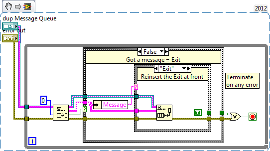
I think the best option is to replace the flush of the queue in the Stop messages with a selective messages waiting managers one by one and check if the output is - if so, reseat it in the front of the queue. All other messages are discared. That look like this, have seen interesting parts...
Here is the message loop to stop with the problem highlighted.
As I'm not mistaken, I think it's better that NEITHER updates the model to avoid this problem.
Here is the case of the resting State in the case of stop message:
Us do not hang the CPU run a constant stream of messages ineffective because we only "Log" enqueue messages when we are in the valid state logging (a State of rest here is again a passthrough).
The worst case, it's that there are number of register requests already in the queue when the system shuts down. After receiving the stop idling message, state transitions and other Log messages become non - ops due to the State.
I consider the opportunity to post a few screws update
~ Simon
Maybe you are looking for
-
Unwanted on a toolbar written my tabs Council loses tabs.
My new tab starts to show the ads instead of the normal nine vignettes. It was after a file download that has obviously been embezzlement. I managed to get the original screen new back by restoring toolbars. At this point, I had all my tabs display.
-
Satellite C660 fan error message - 18 c
Hello. My laptop was working fine until today when I kept getting an error message, 'Warning' and reads as follows: "WARNING: a problem with the cooling system has been detected." (Next line) Please, turn off computer immediately and return it for se
-
CO5110Y BIOS will not allow edits LAN or video BIOS version 5.38
Hello I have a Compaq CQ5110Y with BIOS version 5.38. My problem is that I need to disable the LAN chip on board. My current BIOS will record the changes to the date and time, but it seems that it will not save the changes to the ADVANCED tab. I adde
-
How to control (or know) the speed of iteration of While loops?
Hello world! Currently, I am implementing a 2 bit counter in LabVIEW. Fortunately, I was able to find examples on the forums of NOR. Yet, in real life, speed of the ILO 2 counters are controlled by a clock switching frequency to produce different out
-
Windows Server 2012 - Folder Redirection
This may sound stupid :/ On my school network my folder redirection is //SERVER/%USERNAME% but can not get group policy to do this on my own server it must be / / SERVER/PART... How would I set up so my folder redirection goes to the root of the shar