The XY graph Plot.LineWidth Property node problem
Hello!
I have a loop, where I repeatedly putting curves in a XY Chart. In the first iteration of the loop, after the first corner appears on the graph (I send data from the graphical indicator), I use a Plot.LineWidth Property node to align the thicker. However, in the next iteration, when the second plotted curve appears on the graph, and the property node is pulled again, the second curve remains thin. I guess what I've done wrong, that this property node defines only the first curve? How can I set the width of the line of all the curves of the XY graph on the same value? When I directly on the properties of XY graph, I can set the width of the curve, but only one by one...
Suggestions how set the widths of the ground on a specific chart XY?
Thank you!
If it is a multiplot XY, you must set each plots properties by using the property activeplot (index of the new lot), then by setting the thickness.
Tags: NI Software
Similar Questions
-
Delete the graphic signals - no historic property node
How can I erase the waveform graph since there is no property node history available for this type of wave form that I can see to set. The waveform has one table, but not the chart. Not sure why it is not the crux of the story, but I don't know there's a way to delete it. Any ideas?
QRP wrote:
How can I erase the waveform graph since there is no property node history available for this type of wave form that I can see to set. The waveform has one table, but not the chart. Not sure why it is not the crux of the story, but I don't know there's a way to delete it. Any ideas?
Use the value property of the graphics node waveforms. He lead an empty array.
Hey presto, graph clears...
-
distinguish between the indicator and controls using property nodes
How can I distinguish between controls and indicators property nodes?
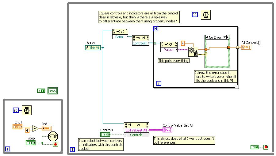
I find that the controls and lights on the Panel before all come from the same class... a digital control and a digital indicator share the same properties... I am trying to find a way to distinguish between the two. I would like to be able to analyse a reference VI pull only the references to the "controls" or "indicators" on the front panel... but when I try this, I shoot all...
Although I found this case a knot of property ' control value: get all ' referral of VI, I can choose between only indicator or only the values of the controls... it's close to what I want, but instead, I like to shoot only the references to the Group of the "indicators" or only the references to the groups 'controls '.
does anyone know if there is a simple way to do this?
Thank you very much!
Suprisigly to search for flags search controls
-
Local property node on the VI Analyzer VS variable
Hi I'm preparing my review of CLD. I had this problem...
I learned that there are two methods to update the icon on front panel using the value of the variable local node and property
It is not a good method to update an indicator using these, but if we want to update a control, then there is no choice...
CLD NOR recommend using the property instead of the local variable node, but when I run my code on the VI Analyzer he created an event
believing that it is better to use a local variable for good performance...
???????
Yes, the text is correct. Property nodes are useful to access things like visibility and string [] in the control of the ring, but for the value, it is much slower than a local variable.
One of the advantages is that there wired error so you can force the data stream, and given that the nodes property are executed in order, you can use a property expanded node to find out what order things occur, especially compared to a free local and free property node, in which case you would be forced to use a sequence structure where ofc is a bad solution.
/Y
-
Issues related to the cell property node: Position Active for a table control
Hello
What determines the Position of the Active cell in a table control property node? I have this in my code and display the value of an indicator on front panel. The displayed value is always set to 0,0. Help for the property node says it's "read - only" so what defines the Position of the Active cell in a table control value?
Define you the active cell with a property node. Once you select an active cell, you can do this cell and single cell-specific things, things like the background value color.
-
You can change the background color vi with a property node?
I was wondering if it was possible in Labview to use a property node to change the background color of façade for an iteration, then back to an original color later. I don't think it's possible, but I would like to know for sure.
Thank you
Jody
You can get the property pane directly node by right-clicking the scroll bar on the front panel and create-> property Node-> color pane. Useful with multiple panes. You can also click the property pane node in example of (imstuck) and choose link and then select the pane.
-
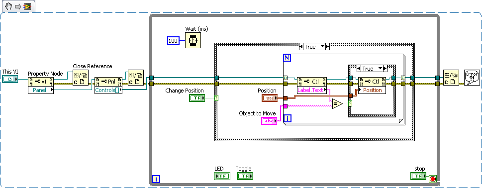
I'm running into a bit of a problem with Labview which until now we were able to kind of work around, but it is more a problem, we are working on our application. I'm using Labview as a user interface to control and retrieve the information of a Zigbee wireless network. Part of our application requires using a large number of Boolean flags on the front panel, each representing a wireless device. From now on, we from our application with a number of hidden indicators and making them visible one by one like devices introduce yourself on our network; This is a workaround for the fact that he doesn't seem to be a way to programmatically create indicators. If I want to change the position of a subset of these indicators properties using property nodes, is it possible to programmatically reference an indicator? For example, that our indicators are named Tag1, Tag2, Tag3, etc.. It would be easier to have a loop that writes the positions to a generic property node that can be referenced to specific indicators, perhaps the entry is a string for the indicator label that can easily be incremented according to the current iteration of the loop for. Is this possible or is at - it another way to do this? Thank you.
Dan
DanRW wrote:
.. .it does not seem to be a way to programmatically create indicators...
This is true; We cannot add new items since she would need to recompile the code running. Your method of masking/display of objects is quite valid, however, and I've seen it used in many GUI.
' This code snippet is similar to Jeff, and yet allows you to enter a name of a control (IE LED indicators are considered as controls in the VI server references) and move it by pressing the change Position of "boolean lock.
-
Graph plot legend colors Signal not updated when mixed with the property node
Hello
We try to put the colors of the trace of a graph of Mixed Signal using a property node. Although we can change the color of the data in the field correctly, the colours of the plot in the legend do not change until some apparently unrelated operator action is performed (for example, to resize the window or by double-clicking a field name). Waveform to XY charts don't seem to have this problem.
Anyone know a work around? I think I saw a similar topic on the forums earlier, but I'm sorry that I am unable to find it now

See attached vi.
Thank you
-john
I should probably have joined the last post of VI, but I have has been a thread of error between the two loops. I also deleted the text you had so I could see the I need to press the button.
-
graph of waveform of filling via the property node
Hello
I want to fill a graphic waveform spirit multiple waveforms by programming. This means, the graph is the main VI, and use it in an another vi reference chart. Firstly I have to solve the correct reference waveform curve, then I use the "Value" property node The value must be the value of type variant, should be no problem. But the property node works only with table 1 d and not 2D.
How can I fill it with table 2D programmatically? I use LabView 8.6, see attached example.
Mitulatbati
Hi mitulabati,
You must specify the data type that you will be feeding to your chart, the default type is an array of 1 D.
To do this, connect an empty 2D array directly on the graph, it will change the input to your waveform parameters and now the property node will accept this new data type.
Hope this helps
-
Problem with the Value property node (MacOS)
Insofar that I tested it, the nodes of property Value (and value (signalling)) do not work under MacOS: value property is a Boolean value, the value (signaling) as a cluster (width, height).
Even with the Boolean controls, the node does not work.
Not such a problem in LV 8.6.
Am I missing something? Is that some 'of use'
 ? Or just a bug?
This looks like some sort of problem of indexing with the nodes property as somesort of corrupted installation. What happens if you just delete the property node and recreate him?
I filed a digital control and looked at the context menu of the list of the nodes property. Below value and value (signs) are Visible (which would be a Boolean value) and Xcontrol, that when you bring through the submenus, the first choice is container bounds, a cluster of Width and Height. If these 2 types of data which are located 2 below in the list match those you found.
What happens if you take another node in property a few elements upwards or downwards in the context menu? Fact is happen for other properties, and if so, are thereany properties who agree?
Here's what look like my property for a digital nodes and I draggged the box up and down to show the natural order of the nodes property. Notice that I have script installed, so there are a few other nodes property (and the blue box at the top) you may not have.

PS. Verify you the signature. Kudos button is now moved to the left since the update of the forum.
-
linking the two sliders property nodes in a graph
Hello
I had a chart with 2 sliders. And I have to be able to set the coordinates of each cursor using nodes of property. "However, if I click on the mouse button right button - create - node - cursor - property cursor position - there are only 3 possibilities of 'Everything', 'X', Y ' that links only to one of the sliders (in fact I don't know who). How is possible to link the nodes property of 2 sliders position to 2 sliders in a chart?
Thank you very much for the discussion.
Martin Pekar
Property nodes run from top to bottom. Resize the node property to the four elements as follows:

and two positions of the wire.
-
How to set the property node maximum xscale for several scale XY Chart
Hello
I use a graph XY with three X axis and three scales of axis Y to draw the three sets of data. This works well.
What I do now is to set the Xscale.Maximum property node for one of the x-axis (the other two autoscale). If I click right in the (Create Blockdiagram; Node property; X scale; Maximum) I can not choose what x-axis I want to put the Maximum for.
So my question: how to select a specific axis allows you to set the XScale.Maximum property node when having several axes?
Thank you for your help, any suggestions are appreciated!
Hello
After some more research and experimentation, I found that using the scale property X Active I can determine/set for which the XScale.Maximum Xscale is used.
This solved my problem.
I hope someone else can save themselves a few hours with this thread!
Thank you
-
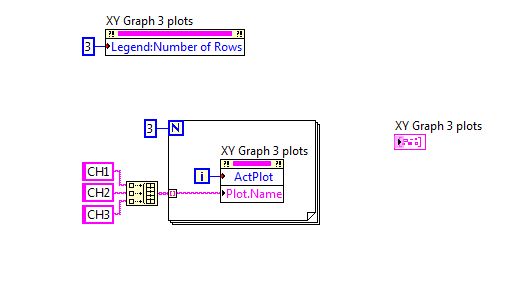
Dynamically manage the names of legend by using nodes of property
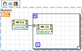
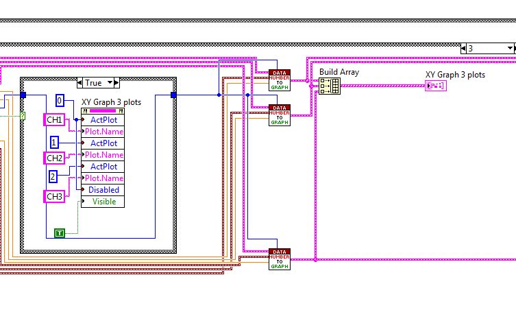
I have to draw several temperature - time data on a XY Chart. Now traced works perfectly fine, but when I try to stup the legend name using property nodes, it gives error if I use something like in the first picture. It seems that the "ActPlot" property cannot access values greater than 1. Works perfectly although for two plots.
I tried to use one for, as in fig. 2, it does not work. It blocks every time ActPlot hits 2.
Suggestions or advice?
Hey,.
Please test the attached VI (registered to 8.2) to define the names of the plot, use it as a Subvi.
BTW, in your second picture you have connected 3 to the connector of the loop for AND and autoindexed table with 3 elements.
Christian
-
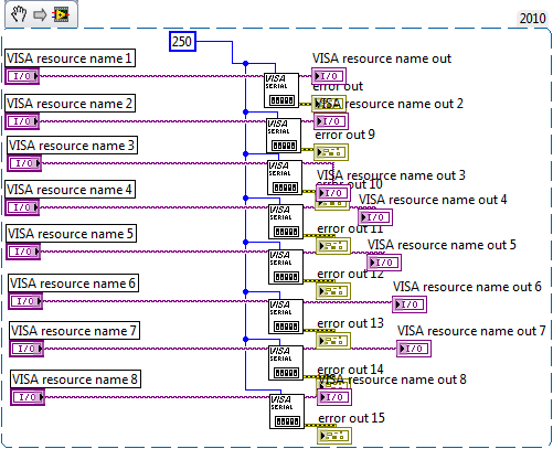
Error: The property node (arg 8) visa to configure the Serial Port
I'm trying to control 8 USB to R232 via a HUB of 10 ports Tripp-Lite (model U222-010-R) and do not have consistent results. Just after rebooting my computer, I have no problem in running the following program: (I tried to download the VI directly but without success, so here's the extract)
I made sure that the COM ports that I select are that one is available on both the Device Manager and in the NOT-MAX. But after awhile, it does not work or if the HUB is unplugged and replugged in (even if the names are correct and up-to-date in devices and NOR-MAX Manager) I get the error code "property Node (arg 8) visa set up a Serial Port (Instr) .vi" I want to be able to see these ports consistantly more without having to restart my computer all the time. Is there a better Setup for this? The previous installation of the computer has a PCI card for it and we have not had any problems with the code, but are facing problems with our upgrade. The old computer ran Windows XP and had cards PCI and the new computer that I am using a Windows 8 and the USB HUB. Thanks for any help you can give!
Mr says:
Jeff,
It is a one off lines from specifications Tripp-lite:
-On bus power, 500mA from the USB 2.0 computer port is shared between hub ports
This would be in support of what I need or not necessarily?
-Mr
No! That's the 50mA by port not 500mA. an order of magnitude full powered USB (if you want reliable - if you want real problems which appears irratically each time only and is a headache to track down which would)
-
How to customize the context menu in the legend of plotting the graph of wave?
I am currently on the creation of a simulation of various control loops as educational objectives. Here, I have a chart in waveform to different signals. Now my question, how to customize the context menu in the track of the Waveform graph legend => when I click on 'image' behind the Plotnames one menu to open options where you can customize the color etc. or plotwidth. But students should not have access to these settings. How can I change or disable this menu? The context menu for the waveform graph, I've already customized by right click on table of waveform-Advanced online-online menu, but for the legend of conspiracy, I have not found this setting...
Thanks for your answers... I tried different things, but I don't see a solution yet :-(
See you soon
DCP
Hi, STC,
There have been a number of suggestions for change or disable the table , right-click menu, but I see that this does not affect the context menu of legend , which is what you ask for help with.
To prevent completely the menu right-click to work, you must disable the chart control entirely. You can do this by double-clicking on the chart and select Advanced Options > active state > disabled. This will prevent the operator to be able to generate a menu right click on the chart control.
If however you still wanted the table, make a right click menu to work, but the legend made a right-click menu will be disabled, I see two options:
1. draw a classic decoration square on the legend and the transparent color. This will prevent the mouse clicks to achieve the legend, and transparent it will not interfere with your user interface appearance.
2 use a Structure of the event to capture the event filter Popup Menu of Activation? for the chart control. You can then use the Coords property to determine if the mouse is over the legend or not. If this is the case, send faithful away? right Terminal. It will refuse the context menu when the user clicks on the legend of the plot.

Maybe you are looking for
-
seplorer window stopped working as a Monte box will flash all the time
Windows eplorer keeps flashingsayingnotrespondingwillnotgoaway
-
For some time I get a lot do not install the updates of Windows. I got more than 20 updates to install the other day and hm 8 could not be installed. I tried again and they have not yet. I ran the update problems, but it just says: we can't identify
-
At the start, after registration on my user, it takes more than 30 minutes to show the desktop.
A dreaded Uni blue screen is shown for ever. Why? What can I do to speed up the start to the top and which is the real question? Windows XP Pro version 2002 service pack 3 Dell Vostro 1510 223 gb hard drive 169 GB of free space Latest version of the
-
Cases & accessories USB901 driver for ESI card reader.
I bought a reader of cards and USB hub, but I can't find a driver for this unit. I use XP SP3. Any suggestions out there?
-
can I use wrt54GS as wireless extension?
Hi, I just want to know if I can use old router wrt54 GS as a wireless extension? Here is my story, I have a router WRT54G2 wireless located on basement and I have laptop connected through wireless and connected via ethernet, now these two portable i