timer output cRIO
Hello world
I'm new with labVIEW but I need help to speed up my studies to a system, I did work.
I work with a cRIO and some AI and DI/O modules.
(1) I have an analog input, an AI, that when she is less than a fixed value, say for example 6, it will give a signal to one that makes the startup of a pump.
(2) my problem is that: when the pump starts, it must not run permanently but every say 20 seconds 40 seconds.
(3) when the signal of the AI is on the value of 6, the pump should stop.
(I did a .vi which works very well with cRIO and Ai, DI/O modules for 1 points) and 3). My problem is point 2) if the pump start I do not know how to make "timered looped" and to stop him when he has to stop (from AI, signal beyond the fixed value)
I hope I was clear.
Thank you very much for your help
Looks like you're very close. I wouldn't put the verification of time within a structure of housing. Instead, do the timer reset when the AI is not more than 6. Do the timer for 40 seconds with an autoreset. This will reset the timer after the 40ms. Just add a little more logical for your outings are on and I think that you will be there.
Tags: NI Hardware
Similar Questions
-
In time real CRIO - writing a file on a PC hard drive
Hi all
I am developing and application with the following hardware features:
Time real cRIO 9004 target device
HAVE cRIO 9205
AO cRIO-9263
and the following programming features:
I run an FPGA VI to establish PID control where the reference signal generated in the FPGA and the real is an acquired signal through the cRIO 9205. I also find target FPGA FIFOs host in order to pass the data from the FPGA to the application of the RT. The time real VI will run in the 9004 cRIO processor. Now, with the data from the FIFO I would write a file (regardless of the extension), in order to do more tests. I did it but I don't want to use the local memory of the RT, instead, there will be a PC (hard drive) where I can place the file in order to write it (with data). I'm not able to do so, as 1) I don't know how to call the PC hard drive and 2) I don't know what communication protocol fits better I want to develop a device to Windows Welcome.
Nobody helps me?
Thank you very much
Enrique
The cRIO-9004 unfortunately has USB, so you can not write on a USB Flash drive (which would be my first suggestion). If you want to store the data on the host PC, you will need to write a simple TCP/IP client/server to send data to the host through TCP so that the host can receive and save to disk. Façade of the VI may seem as it is running on the PC, but it's actually just show you data be listened to the target (you are not allowed to piggy-back on this same Creek).
There are several examples of TCP/IP client/server integrated into LabVIEW.
-Danny
-
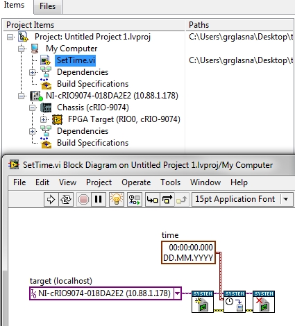
Set the time on cRIo with delay VI
Hi all
I want to correct both the cRio and tried to use the time VI. It gave me error 2147467263 which means "not implemented". the error message is "node in nisyscfg.lvlib
 and Time.vi:6150001-> put time.vi".» I don't know how to fix this error and to change the time.
I've attached a screenshot of the program to this message, I would appreciate any ideas or suggestions.
Best regards
Hello imnewhere
run the vi in my computer, then it should set the time.
This may also help
How can I configure my controllers time real CompactRIO to synchronize with the SNTP servers?
-
time real cRIO and confusion of FPGA
I'm confused on the use in real time or FPGA.
I learn from training material, you use cRIO with FPGA and real-time, you have two
synchronization means: one is the analytical engine, another is calendar FPGA. However, the frequency of synchronization
real time is limited to 500 Hz, see attachment.
I wonder, if I want to acquire samples using 5 k rate of real-time data acquisition card
system, such as cRIO and sampling interval is 1 Hz. That is, using a timed loop which is 1 Hz and inside
the loop, can I use DAQmx to acquire waveform using5k rates? or I have to using of FPGA to acquire waveforms
Whe I want to acquire signals with greater than 500 Hz rate?
cDAQ is not an FPGA, but use DAQmx.
-
For a sequence in real-time output variable
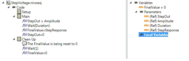
VS 2011, I have a sequence of real-time voltage step that sets an AO for a voltage given for awhile, and then resets the output to 0.
Just before setting the output to 0, I want to read the response of my this stimulus of an AI System I call StepResponse. To do this, I place this in FinalValue I set as a Variable in my script. In other words, it is a parameter or a local Variable.
Now, how can I get this out FinalValue? I don't see anything on how to "test" this variable to one of my user variable... I was able to do with the stimulus inherited in VS2010 Editor. Now, I'm stumped.
Here is the sequence:
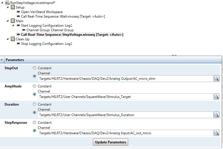
and this is the profile of stimulus and settings below. I can set the fine settings via the API of LV, or run the Publisher of the Stimulus. But I can't seem to get out this FinalValue...

THX.
L.
The return for a sequence (in your case FinalValue) variable is returned to the caller once the sequence has been completed as a result of this sequence. In your example, the appellant is stimulus profile that you configured. In a profile of stimulus, two relevant things will come based on the return value of variable a sequence called:
- The return variable value will be get recorded in the file of test result ATML for stimulus profile
- You can configure an assessment of output for the call to test sequence make a basic on the return variable test to determine a pass/fail result. For a numeric variable to return such as FinalValue, you can do a check of numerical limits to test whether the value is in or out of the specified limits. For a Boolean return value, you can translate either directly in a pass/fail result, or you can reverse the logic as well as False implies Pass.
In addition, the LabVIEW API has a function, you can call once the sequence finished to programmatically retrieve the return value.
However, in your sequence after that you store the value StepResponse in the return variable, you reset to zero before the end of the sequence. If your sequence always returns zero. I think that you do not remove this line and let FinalValue what so that you will get the StepResponse back closure instead of zero value.
-
How to set the time sync cRIO SNTP in MAX
I try to have my cRIO-9022 automatically synchronize with my network using SNTP time server. I read the KB on how to add the SERVER code in the file of ni - rt.ini can be found here: http://digital.ni.com/public.nsf/allkb/F2B057C72B537EA2862572D100646D43?OpenDocument
I LV 2010 and that you have installed NI time 1.1 on the cRIO.
According to figure 2 in this white paper titled "Timing and synchronization in NI LabVIEW", this time to synchronize with the SNTP functionality may appear in MAX.
http://zone.NI.com/DevZone/CDA/tut/p/ID/11466
I succumbed to send, any ideas?
Thank you
Hi Jim,.
I have install time on another cRIO, and similarly, I was not able to use the IP address of time.windows.com (207.46.197.39) you used in your ini file. I was however able to change the IP address to the previous (132.163.4.103) and it worked correctly.
I'll file a bug report on the time server Microsoft, to better understand why that might happen, but could post you as well as the 132.163.4.103 address can make it through your firewall?
I'll also try to track down a cRIO-9022 and test your image; I'll let you know if I run into trouble.
-
Hello guys,.
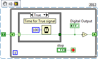
I am trying to create a simple VI to generate two outputs analog square with USB-6009. Each output supplies a LED and it is necessary that single LED shines at the time - so when Out0 is active, Out1 is zero and the other way around.
To get started, I created a VI in which the goods are made manually by Boolean and it works fine (square v1.vi of signal).
But I need the output to switch automatically after the amount of time given (I needn't of high frequencies, at about 1 Hz). To do this, I changed "square wave v1.vi" in "square wave v2.vi" and set the Structures of the case in an another While loop which would be timed by the wait function (ms). The idea was that the loop internal would turn the output rate of frequency while the outer loop would ensure a continued implementation of the programme. But the reality is very different and my low level of competence (this is my first VI) let me down. Could you please help me out of this? I appreciate all the advice.
To summarize: The VI must be continuously running program that generates two dependent signals with adjustable amplitude and opposite phases (Out0, when active, Out1 is zero and vice versa.). Signals must be switched automatically to the given frequency.
Here's a simple flip-flop - while time the loop runs, the Boolean line connected to the digital output passes from true to False to True... with the schedule determined by the time you put in waiting for him (note that you can have regardless of the different times for the true = on and False = off case). Of course, the life of signal (represented by 'Digital output') 'inside' this loop - you have to put the 1 point 1Line DAQmx VI write digital Boolean inside the loop, or find a way (for example, a queue) to get the data between the inside and outside.
-
Run time output of DBMS_OUTPUT. PUT_LINE
I would like to know why DBMS_OUTPUT. Put_line output gives only after the end of the execution of the procedure. I wonder why Oracle has not provided a package for the output of the run time.user10566312 wrote:
I would like to know why DBMS_OUTPUT. Put_line output gives only after the end of the execution of the procedure. I wonder why Oracle has not provided a package for the output of the run time.It's because of the client server architecture.
SQL and PL/SQL processes run on the database server.
The database server has no access to clients, or screen keyboard, so cannot accept entries to the client keyboard, or write the output to the screen of the client.
When the client software issues a statement to the database, it uses something like for example of SQL * more to establish a connection to the database, submit this request to the database and then waits for the request to complete, eventually return some results from that (e.g. the results of a SQL query).
DBMS_OUTPUT does not write to any screen... it puts just the data that you specify in the DBMS_OUTPUT buffer. It is then up to the client software to request the contents of this buffer, but the client software cannot do that when the request he made was finished (only a single statement between client and server can be converted at any time). That's why you issue your request so the output once the query is complete.Oracle provides a way for you to run output at the time, if you want to start doing things with the DBMS_PIPE package, etc., although for the follow-up of the execution, I have a package that writes my 'output' to a table on the database by using an autonomous transaction and then the content of this table can be viewed from a second session While the first session is still being requested process. Similarly, you may have your 'exit', writes to a file on the database server using something like UTL_FILE and then you would be able to view the contents of this file running, as long as you open and close the file and make sure file buffers have been empty etc.
DBMS_OUTPUT is not the tool to use if you want to display the output of the run time. It's not a fault of Oracle, it's just your lack of understanding of what tools do this work. ;)
-
Optimization of DMA in the Code in time real (cRIO FPGA-> RT)
Howdy,
I am acquiring data from a microphone using the NI9234 module. I wrote my RT and FPGA code. I am communication of data between the FPGA and RT layers using a DMA FIFO. I noticed that the layer of RT has difficulty to empty the FIFO, since the FPGA layer runs at a much faster pace. I would like some pointers or suggestions on stupid things I do in the layer of RT that are causing it to run more slowly than necessary.
Currently, my RT code simply opens the FPGA reference in a loop, extracts data from the FIFO and writes to a file. I know that if I want to plot the data or perform an FFT on it, I would in a loop of lower priority, for not to slow down the data streamed from the FIFO. Are there accessories simple performance that I'm missing in my code? Thank you.
I enclose a copy my code FPGA and RT (screenshots and screw), so that you can watch.
I would seriously consider redesigning completely the code and using this reference request model.
http://zone.NI.com/DevZone/CDA/tut/p/ID/9196
There are reference points that show how this model makes. With the acquisition of waveform, there are a lot of optimization. This referenace application addresses all these to give you the best performance.
-
Daylight Saving Format Date/Time String vs get time in seconds
Hi all
I have developed a real-time application using a cRIO 9074 which has two loops. The first gathers data and records the time using the module of ' string of Format Date/time ' with the following time sting: '%d/%m/%Y % H: %m ". The output is a sting with mouth/day/year hour: minute.
The second loop Gets the cRIO time using the module "get Date/Time in Seconds ' and the output of timestamp is sent by a shared variable for an application that is running on a local computer.
The problem started Sunday last with DST. With the help of MAX I am able to see that the time of cRIO is bad (1 hour less) and that him "automatically adjust clock for daylight saving time" is not checked and gray, so I am not able to change it.
The time of the first loop by using the "Date and time Format string' returns the time elapsed between the cRIO (1 hour late), however the time of the second loop is OK. I have manually corrected time using MAX, so now the first loop is correct, and the second is now over an hour.
Any ideas?
Dear RavensFan, thank you very much for your answer.
However, this was not the problem. Apparently the result with or without the element of DST is the same. I solved the problem, for now, by changing a parameter not on the function "get Date/Time in Seconds" but on the time stamp indicator.
By right clicing the indicator and go to the display Format and the advanced editing mode, I have changed the Format string to a universal time container of this: %< %="" h:="" %m="">< t="" %="" ^="">< %="" h:="" %m=""><>
Apparently the time from the 'get time in seconds' is still an hour longer, but now it is correctly displayed.
-
nismECATAdapter.dll not found error - cRIO 9082 RT
Hello
I'm a real-time 9082 cRIO system deployment. During startup, the console displays the error above, but I can't find anything referring to this dll online. It is as if it does not exist. My best guess is that it's an adapter of EtherCAT OR? Here is the full output to start the Console:
----
Datalight Reliance v2.10.1053
Copyright (c) 2003-2006 Datalight, Inc..Executive in time real LabVIEW
Construction time: 5 June 2014 14:22:59
(C) copyright 2002-2014 National Instruments CorporationMAX system identification name: Chassis1
LabVIEW time real SMP kernel: processor cores found: 2
The initialization of the network...
Dev | Op M | Link | Pilot | MAC address | /Mask IP address | Mode of the adapter
* 1 | Int | U | i1000e | 00802F17EE7A | 10.0.1.241/24 | TCP/IP (static)
Dev | Op M | Link | Pilot | MAC address | /Mask IP address | Mode of the adapter
2. Int Jolie; nigev | 00802F17EE7B | - -| People with disabilities
Time synchronization source: TPP now active
00802F17EE7A device is now connected
System Web server started
Application Web Server launched
Error! nismECATAdapter.dll not found! (dependency)
SoftMotion Module initialized.
OR Scan Engine initialized.
NOR-RIO 14.0.1 server started successfully.Start application: c:\ni-rt\startup\startup.rtexe
NI-VISA 14.0 Server started successfully.
Welcome to 14.0 LabVIEW Real-time
--
I hope that someone out there has seen this before dll?
Thank you
Looks like you need to install the driver the cRIO EtherCAT or your system. Here is a link to EtherCAT for Windows driver: OR-Industrial Communications for EtherCAT 14.0 - Windows
-
AirPort Extreme & Electrical Outlet Timer
Hello
I have the newest AirPort Extreme (http://www.apple.com/shop/product/ME918LL/A/airport-extreme?fnode=7f) and I recently moved to my room in my basement to the second guest room floor providing a 2.4 GHz and the private network wifi 5 GHz (two separate networks) to my house.
I read on the sleep disorders causing wifi signals and how it can cause generally negative effects be exposed continuously to EMF signals.
What I'm wondering is it would be harmful to my AirPort Extreme to put it on a timer plug (ELS https://www.amazon.com/Enover-Programmable-Digital-3-prong-Appliances/dp/B0191ZG/ref = sr_1_2? ie = UTF8 & qid = 1469557186 & SR...) so that I can program it to turn off the power to the router around 11:30 and turn it on again around 06:00; eliminating privileged exposure to EMF for me and potential customers during the hours of sleep?
I understand that many of us may be divided or not there is any real effect signals wifi on sleep/general health-it's NOT what I'm asking.
Everything interests me is whether or not it would be damaging for the router AirPort Extreme to cut the power at night via a programmer power socket and then to restore it again in the morning on a daily basis. It will shorten the life expectancy of my router? This will degrade the quality of my wifi over time signal? Thank you in advance for the answers!
-Scott
"What I was wondering is it would be harmful to my AirPort Extreme to put it on a timer output so that I can program it to turn off the power to the router around 11:30 and turn it on again around 06:00; eliminating exposure to EMF for me and potential customers during the hours of sleep first? »
The debate about so consistently turn a device and off is better or worse that just leaving all the time has happened since household electronic appliances were introduced.
One school of thought argues that constant power down and the cycle puts more emphasis on the electronics inside that just letting the device at any time and this extra stress can lead to a shorter life for the product.
Another school says it does not matter as the power on and off the power of everyday, or has left the whole time that the life expectancy of the product is concerned.
Make your choice... good arguments can be advanced for or against powering a device works every day. Call him a link if you want, or return a coin.
Personally, I lean toward the school "let him", if not because the internet connection and network is likely to be more reliable in this way. In other words, if you turn off the airport at night and power it back up the next day, the airport will lose its Internet connection and network and be forced to establish a new connection when it is consumed in back to the top, with more chance of something going wrong.
Although I leave the airport on almost all the time, if I'll be gone for a few days or more, then I usually turn off the airport if I remember to do it before my departure... to save a few pennies on the electricity bill.
-
Hello
I want to set the time on the cRIO, but on the function Panel, it lacks a lot of screws for RT Utility. For the time setting cRIO is RT Set Date and Time VI but it does not appear on the Panel of the function.
-
Writing in the remote file of the cRIO
On a real-time cRIO, I would like to create a reference to a file on a remote network storage device. I know it's possible to do this from a Windowsxp PXI chassis by plugging
- in the utility opened file, but it doesn't seem to work from a time-frame real cRIO. Is it possible to create a reference to a remote file from a time real cRIO? No, it is not possible. cRIO devices do not have access to shared network drives.
-
RT - set the time of real-time target in MAX
Hello
I want to manually change the time on my target in time real (cRIO-9022) with MAX
I followed the steps described here.
In step 2, when you install the remote system OR 14.5.0 Configuration Support
I get the following error message when you try to install:
"Labview real-time 12.0.1 requires the service locator 1.0".
On the host computer, I had SP1 2013 Labview with the module time real 13.0.1
On the cRIO, I'm under Labview RealTime 12.0.1
I installed SP1 2012 Labview real-time Module on the host computer and tried 12.0.0.
Then, I received this message:
"Remote Server for Labview RT 13.5.0 requires Appweb 13.5.0
Engine for Services execution Web 13.5.0 requires NEITHER System Web Server 13.5.0
LabVIEW Real-time 12.0.1 requires the service locator 1.0 ".
I searched the forum with no luck
Any help I appreciated.
BR
Arne M
Hello
I solved the problem.
Just had to select the correct versions of all additional software necessary
Support remote Configuration OR system 5.6.0 etc..

Maybe you are looking for
-
H P want 7640 printer: HP Envy 7640 cannot print borderless
I can not print prints of borless. There is no place without borders to check in the settings. On my pictures, all I want is without borders. I uninstalled the printer and reinstalled. Has nothing. I've updated the driver. Has nothing. I must be miss
-
LaserJet Pro M127fn MFP: Stuck "print fax page 1.
I had to receive two pages of fax. After that the first page has come through it is stuck "print fax page 1. The second page is never good. I can't print anything. I already disconnected my printer and plugged in. When the rear connection, it uses th
-
PhotoSmart e-all-in-one B210a: I choose the HP ePrint (tray) paper source?
I want to find a way to print photos on my iPhone using HP ePrint mobile app. The all-in - one HP B210 - has a dedicated photo tray, but when I send a print job, the printer uses the default main tray and plain paper. Is it possible to tell the print
-
Where can I find a description of the indicators in this line of .jad file: RIM-MIDlet-flags-1: 35 Thank you
-
An error [-5005: 0 x 80070002] occurred during execution of the installation of magictune
Original title: uninstall magictune I am running Windows 7 64 X. By mistake I have install MagicTune Premium. My laptop is Toshiba Satellite P799 with Nvidia GT 540 M. I tried to uninstall it using the program and functionality but receive the fol