Trigger 6259 & 6025
Tags: NI Hardware
Similar Questions
-
PCI 6259 - Trigger HAVE voltage measurment when P0.31 varies from low to high
I write a model that uses the output digital (P0.8 - P0.31) and you want to trigger a tension measured on AI16 when P0.31 varies from low to high. Any ideas on how to achieve this?
Almost what Michael said...
michael_lewis23 wrote:
Have you looked at an example in the finder for example LabVIEW? You can export a digital signal connect your p0.31 signal using a wire to a PFI line on the DAQ card. For a task of analog input, you can place a DAQmx Start Trigger VI and choose the use a clock source external sample under the line of PFI where the digital signal have been exported to.
Best regards
-
How to connect USB 6259 so that I can generate trains of pulses of a meter
Hello
We just bought NI USB-6259 BNC. We used to use BNC-2110, which integrates the connectors BNC for trigger and the meter so that we can send trains of pulses through it to our electric Stimulator.
However, I find no terminal BNC for the output of the meter on the new device. Could someone teach me how do?
Thank you
Jay
Hi, Jay.
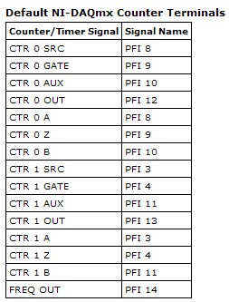
Big question. The screenshot below will give you the Signal of Counter/Timer associated with its respective PFI line:
This table is located in the NOR-DAQmx help (using terminals of NOR-DAQmx devices"OR USB - 6259 BNC).
To access these lines PFI one of the BNC (User 1 and User 2) user-defined, the line due to PFI line of the user desired. For example, if I wanted to access counter 0 Out of 1 BNC user, I would wire pin 1 USER on pin 12 of PFI. Manual specifications USB-6259 BNC does not give a good description of how to access the user 1 and user 2 BNC, so I refer to page 9 of the Manual of the BNC-2110. It's the same idea, just different pinout.
Let me know if you need more information. I hope that you are having an amazing day!
-
the analog inputs with digital edge trigger
I am currently triggering a readout with a digital trigger using a 0 - 5v as the digital source encoder. I am running LV 8.2.1 DAQmx 9.0 and a PCI-6259. I use a VI I wrote and which is very similar to 'Acq & chart voltage-Ext Clk.vi', and using the one-pulse encoder connected to PFI8 as the clock source for the sample clock vi. The only major difference is using the channel of the Z-trigger as a software reset inside the While loop with the DAQmx reading. Currently, the sample clock doesn't allow that either read the lower edge or an increase of PFI8, so I get a sample by one-pulse.
I need to double the rate of analog playback for a given tree rpm and encode them, so I need to read on the fronts and edges of the one-pulse encoder. The sample clock can be reconfigured for the detection of changes and still read the PFI8 port to increase and decrease as inputs of physical channel, or do I have to configure detection of modification of the task/digital input for a single line and use the "ChangeDetectionEvent" as the source for the sample clock HAVE? Detection of Timing/change DAQmx can still use the signal in PFI8, or should I use DI ports, and which ports are DI should I use?
Thanks in advance!
In fact P0.8 is. I was looking at the pinout for the 6251, no 6259. Sorry about that.
-
How to read from the beginning to reference trigger?
Hello!
I develop a system a little on a NI DAQmx 6025 and want to know how can I get data from an early relaxation of reference.
I use "AcqVoltageSamples_IntClkDigStartAndRef.2008" to control the unit in c#
If I set up the Starttrigger only, I can trigger... (the measure is to start by climbing aboard PFI0)
---------------------------------------------------------------------------------------------------------------------------------------------------------------------------------------------------------------------------
myTask.AIChannels.CreateVoltageChannel (physicalChannelComboBox.Text,"", (AITerminalConfiguration)(-1), rangeMin, rangeMax, AIVoltageUnits.Volts ");
myTask.Timing.ConfigureSampleClock ("", sampleRate, SampleClockActiveEdge.Rising, SampleQuantityMode.FiniteSamples, 1000);
myTask.Triggers.StartTrigger.ConfigureDigitalEdgeTrigger ("/ PFI0/Dev1", DigitalEdgeStartTriggerEdge.Rising);
Reader = new AnalogMultiChannelReader (myTask.Stream);
...
drive. SynchronizeCallbacks = true;
drive. BeginReadWaveform (-1, New AsyncCallback (myCallback), null);
... MyCallback...
data = reader. EndReadWaveform (ar);
---------------------------------------------------------------------------------------------------------------------------------------------------------------------------------------------------------------------------
Now, I want to stop my measurement by the trigger of the reference, so I set up the Referencetrigger on the same source (PFI0)
myTask.Triggers.ReferenceTrigger.ConfigureDigitalEdgeTrigger ("/ PFI0/Dev1", DigitalEdgeReferenceTriggerEdge.Falling, 10);
(This line is after the configuration StartTrigger)
If I start the task and give the triggersignal, the measurement starts. But now the measure must stop if I start PFI0 again!
I don't know what I have to do to become a measure from the beginning to trigger Stop... I mean PFI0 PFI0 rising Edge edge
Thanks for the support!
Suchen für alle die noch immer nach einer Antwort, ich habs jetz!
For all who are looking for this answer, I get it now!
--------------------------------------------------------------------------------------------------------------------------------------------------------------------------------------------------------------------------------------------------
myTask = new Task ("aiTask"); Create a new task
Initialize local Variables
Double sampleRate = Convert.ToDouble (rateNumeric.Value);
Double rangeMin = Convert.ToDouble (minimumValueNumeric.Value);
rangeMax double = Convert.ToDouble (maximumValueNumeric.Value);
Create a virtual channel
myTask.AIChannels.CreateVoltageChannel (physicalChannelComboBox.Text, "", (AITerminalConfiguration)(-1),
rangeMin, rangeMax, AIVoltageUnits.Volts);
Set up sync Specs
myTask.Timing.ConfigureSampleClock ("", sampleRate, SampleClockActiveEdge.Rising, SampleQuantityMode.FiniteSamples, 1000);
Configure start and reference triggers
myTask.Triggers.StartTrigger.ConfigureDigitalEdgeTrigger ("/ PFI0/Dev1", DigitalEdgeStartTriggerEdge.Rising);
myTask.Triggers.ReferenceTrigger.ConfigureDigitalEdgeTrigger ("/ PFI0/Dev1", DigitalEdgeReferenceTriggerEdge.Rising, 100);Check the task
myTask.Control (TaskAction.Verify);
Create the object reader
Reader = new AnalogMultiChannelReader (myTask.Stream);
Start the task, and set the playback position
myTask.Start ();
myTask.Stream.ReadRelativeTo = ReadRelativeTo.CurrentReadPosition;AnalogWaveform
[temp]; {while(!myTask.IsDone)}
Temp = reader. ReadWaveform (60000);
}myTask.Dispose ();
--------------------------------------------------------------------------------------------------------------------------------------------------------------------------------------------------------------------------------------------------
Mit dieser Lösung kann man von mension zu messen mension.
With this resolve you can measure from edge to edge.
-
With the help of a NO-9401 read the angular Position and trigger a reading I
Hi all
I am writing some software dependent vs angle chart and to the monitor when the buttons are pressed. The software allows all DAQ lines to be configured so that multiple configurations data acquisition can be used.
Currently, I peut use my NOR-9411 read the angular position of my quadurature encoder and trigger the playback of my entry (measured with a NEITHER-9219 or 9237) load on a rising edge of A or B input terminal analog. Also, I can configure the software to do the same thing with a card OR-6259.
My problem is that when I switch to a NO-9401 to read my meter task, I can no longer use the input terminals A or B to trigger my analog input. I get error-200414 saying that the entry A (PFI0) is an invalid clock source.
I know that the 9401 is configurable by nibble for input/output lines0:3 and 4:7, but how that affects the ability of a trigger, a route line PFI?
Measurement and Automation Explorer shows it as an acceptable way of PFI0 AI/StartTrigger and AI/SampleClock.
I joined the my code section that defines the tasks and that causes the error. You take a look in the Utilities folder and open the Tasks.vi create.
I am writing in LabVIEW 2011.
Thanks for any advice,
Rob Afton
Test lab engineering intern
Found my answer here if anyone has the problem:
-
How to set up digital channels to change values on the trigger and the counter in c#
Hello world!
I work with the driver NI - DAQmx 6025 and want to know, how do I configure the digital channels in c# for control lines different ports by trigger rising "PFI0" and the meter "ctr0.
digitalWriteTask = new Task();
digitalWriteTask.DOChannels.CreateChannel ("Dev1/Port3 / line0:7", "", ChannelLineGrouping.OneChannelForAllLines);
digitalWriteTask.Control (TaskAction.Verify);digitalWriteTask.Triggers / / how to configure to change Digital line on rising "PFI0"?
digitalWriteTask.Timing / / how to configure to change Digital line on County "ctr0?
-------------------------------------------------------------------------------------------------------------------------------------------------------------------------------------------------------------------------------------------------------------------
Hi an alle!
Am mit dem OR-DAQmx 6025 und möchte like wissen, die ich wie digital channels in c# konfigurieren muss um einzelne Ports der Leitungen auf dem Trigger "PFI0" und dem Zahler "ctr0' anzusteuern.
digitalWriteTask = new Task();
digitalWriteTask.DOChannels.CreateChannel ("Dev1/Port3 / line0:7", "", ChannelLineGrouping.OneChannelForAllLines);
digitalWriteTask.Control (TaskAction.Verify);digitalWriteTask.Triggers / / Wie konfigurieren, um den logical Pegel eines feature pine bei der der zu winds PFI0 goods?
digitalWriteTask.Timing / / Wie konfigurieren, um den logical Pegel eines pines beim ctr0 zu go digital?
NEITHER told me, with the NOR-DAQmx 6025 driver not supported!
ICH habe von NOR learn, dass dies mit der 6025 OR AQmx supported wird nicht!
-
USB6259 static with digital trigger
Hello
I have a VI that controls a control of linear motor with digital lines. At one point in the program setting one of these pipes triggers a task of analog input and a task of Pulse counter. This is done by putting a wire between the digital line and for example. PFI0 use this as a the input trigger. This works well.
My general question: is it a solution, where I can use an internal signal of the 6259 avoiding the connection of the wire?
Matthias
Hi mq17,
I have found no clear information, saying that it is possible (or impossible). What you should try is to create an internal route between the digital line and PFI0 using the DAQmx connect Terminal VI. I can't guarantee this will work, but it's worth trying:
DAQmx connect terminals (VI)
http://zone.NI.com/reference/en-XX/help/370469AA-01/lvdaqmx/mxconnectterminals/
Don't forget to unplug the terminals at the end of your program
Best regards
-
Repeating the trigger with Start.Retriggerable
I have a DAQ PCI-6259 (M-series card) card I am programming with DAQmx. I would like to know if there is a limit in terms of how close together you can use Extensible triggers. I intend to use a frequency of internal clock to 1us. An asynchronous external TTL signal will be used to trigger a finite sequence of digital output of the 6259. The finished digital sequence is 4 samples of long, so it will take 4us. The edges of the asynchronous trigger will happen on every 100us. I intend to use the property Start.Retriggerable = TRUE trigger so that I can repeat this generation 4 sample every time the external TTL signal is received.
Is 100us too close together? Is there a limit to how closely together, you can repeat a hardware trigger when using Start.Retriggerable = TRUE?
Is it possible to know if my card PCI-6259 even supports the property trigger Start.Retriggerable?
100 US will be very well (time to rearm is the order of a tick or two, 10 timebase s ~ ns).
However, the M series supports digital output directly redeclenchables not. Instead, configure a redeclenchables counter finished output to generate impulses 4 to 1 MHz (this example uses two counters embedded M-series). Use the output of the internal counter as the sample for a task of digital output clock continuous who will repeat your 4 sample sequence.
Best regards
-
Software player with equipment trigger events
Hi all
I'm trying to synchronize a number of tasks (software and hardware) to a hardware trigger, where my DAQ (PXI-6259) receives a brief pulse TTL of a box no - PXI elsewhere. I want to listen to this impulse, respond by performing a number of tasks (incl. Configuration of another instrument non - PXI to take a reading via a USB connection to the computer and reconfiguring a switching matrix (PXI-2532)) and loops. It seems that the VISA library can expect a VXI trigger via:
...PXI_status = viOpenDefaultRM(&PXI_driver);PXI_status = viOpen (PXI_driver, "PXI12::12::INSTR",VI_NULL, VI_NULL, &PXI_DAQ);...PXI_status = viEnableEvent(PXI_DAQ, VI_EVENT_TRIG, VI_QUEUE, VI_NULL);...

while (true) {

PXI_status = viWaitOnEvent(PXI_DAQ, VI_EVENT_TRIG, 30000, &PXI_eventData, &PXI_eventHandle);

// Do stuff here. Break if done.

}
and the hardware interrupt itself can be configured using the DAQmx libraries:
DAQmxCreateTask("Epoch Trigger Task",&DAQ_EpochTriggerTask);
DAQmxCreateDIChan(DAQ_EpochTriggerTask,DAQ_EpochTriggerChannel,"",DAQmx_Val_ChanPerLine);   DAQmxDigEdgeStartTrig(DAQ_EpochTriggerTask,DAQ_EpochTriggerChannel,0) // 0 = rising edge
So, my question is how to get the hardware trigger generated since the acquisition of data so that it is detected as a VXI trigger?
Thanks in advance - CDE
Comment of final - I had to change the lines I used on port 1 to a line that I used on port 0, and triggering now works as expected. I have all 326±10 µs delay between the trigger amount front and a pulse response on a separate line (port2.line6). Hope it will be useful for anyone who reads this thread then.
Final code:
// Configure the dummy task to listen for the trigger
DAQmxCreateTask("T_di_ETr",&DAQ_Task_EpochTrigger);
DAQmxCreateDIChan(DAQ_Task_EpochTrigger,DAQ_EpochTriggerChannel,"",DAQmx_Val_ChanPerLine);
DAQmxCfgChangeDetectionTiming(DAQ_Task_EpochTrigger,DAQ_EpochTriggerChannel,                                                  DAQ_EpochTriggerChannel,DAQmx_Val_FiniteSamps,1);
// Wait for trigger signal double timeOut = 10*60; // 10 minute timeout, units of seconds time_t start = time(NULL); while(abs(difftime(time(NULL),start) <= timeOut)) { // individual waiting events have a 10-second timeout (in s). DAQ_Task_Err = DAQmxWaitUntilTaskDone(DAQ_Task_EpochTrigger, 10.0); if ( DAQ_Task_Err >= VI_SUCCESS ) { printf(" Trigger Recieved.\n"); DAQmxStopTask(DAQ_Task_EpochTrigger); break; } else { if ( DAQ_Task_Err == -200560 ) // -200560 = TIMEOUT code { printf(" Waiting for Trigger...\n"); if ( abs(difftime(time(NULL),start) > timeOut) ) { printf(" Trigger Timed Out. Exiting.\n"); break; } } else { printf(" ERROR waiting for Trigger.\n"); break; } } }Only last issue is management of errors in the final version of the code.
-
AI trigger and measure multi channels
Hi all
I have a simple problem (using USB-6259).
can repeat the measurement trigger of AI and measure multi channels, but not both at the same time.
-DAQmxCreateAIVoltageChan(hd, "DEV1/ai0",...) define the ai0 as the trigger channel
-DAQmxCfgSampClkTiming
-DAQmxCfgAnlgEdgeRefTrig
-DAQmxStartTask
-DAQmxReadAnalogF64 (hd, "DEV / ai0:3 ', / / I want to measure more channels"ai0:3"not just"ai0")
Thank you
Hassan
Hi Hassan,.
If you use an analog trigger with several analog channels, you will need to use the APFI0 input as source of relaxation. See this KB: Why do I get error-200264 when running analog reference trigger? All you need to do is to connect your analog signal online 0 to APFI0 (Paperback 20 in your case) and set the source of relaxation at APFI0.
The reason is that you don't have that an NOC on Board (series E or M) and she's going to have to switch between the different lines (see this KB: modes of sampling). This parameter collides with the idea of a trigger analog reference on a specific line (constant sampling of data in a ring buffer up to what a condition is met). The APFI0 line, however, has its own CDA. Therefore, it can run simultaneously.
However, please note that the ADC is fast but has lower resolution to HAVE it sampling ADC. See these KBs: series E and M series Analog Input Trigger resolution, be aware of a possible error between the analog trigger threshold and the value of the first sample
Hope this clarified the issue.
Best regards
Peter
-
Good afternoon friends,
I'm looking to synchronize a finishes analog output signal with a digital output signal end of same length (number of samples). Ideally, the signals should be identical except for the amplitude... 5V for life. I guess that this will require a trigger to start shared? Any who have an example or knows where I can find an example of synchronized finished AO and? My hardware is a PXI-6259.
Thank you
Zach
Hello Super!
Thanks for your post! One of the ways that I would like to synchronize your AO is to use the timing engine AO as your sample for both clock. In this way, you know that you are using the same sample that is generated on board the 6259 clock. Just be sure to start your task before your AO so that when when the AO starts and generates the sample clock the task sees the first front. Essentially you will be triggering the DO with the task of the AO. Take a look at the screenshot of the block diagram that I made that does exactly this. I checked with another DAQ card to ensure synchronization. Let us know if this helps and and take a look at this area of developer who talks about sync multifunction.
Synchronization of series M with LabVIEW and NOR-DAQmx
Have a great day great and let us know if this helps your applications!
See you soon!
Corby_B
http://www.NI.com/support
-
Measurement of frequency triggered? NEITHER 6259
I'm trying to work out how to implement a measure of frequency (of a pulse train) which will be triggered by another external pulse to a different channel.
I have an encoder that is attached to a rotating shaft, that generates square pulses 5V on two different channels: the first string gives one pulse per revolution of the shaft (my planned trigger pulse), the second string gives a pulse all the 1/2500th of a revolution (IE all 0.144º)
Seeing a pulse of "channel one" (the pulse of a time-by-rev), I want the system to begin to measure the frequency of the pulses on the 'two way '. This isn't the average frequency during the ENTIRE revolution I'm after: what I'm shooting looks more like an angle vs revolution frequency waveform graph, for a ride (IE with 2500 data points).
It does not matter if the processing time means that the system of "lack" an impulse to start on the next revolution, because it can always wait for the next. The most important thing is that the beginning of the frequency measurement is triggered at the right time.
So far, I have used L'Express VI/DAQ Assistant to implement a measure of the frequency of the pulse 0.144º: I'm wiring these impulses to PFI9/CTR0 of Council 6259. I used a continuous acquisition of 2500 measures. The expected frequency range is about 40 to 200 kHz (2500 pulses per rev at between 1000 and 4000 RPM.)
That works very well, and I can establish a curve of angle vs. frequency of revolution, BUT... For now the beginning of the acquisition is completely arbitrary; That is, it starts when I type 'run '. I can't understand the best way to trigger the acquisition of the OTHER channel impulse.
There is no external trigger options in the DAQ assistant page, so I wonder if this is still possible using an express VI - do I have to use lower level stuff?
I am convinced that this should be easy!
Thanks in advance
Theo
Rico, Brad,
Thank you very much for your comments, I'm pleased to say that we have sorted in the end.
The first question concerned the fact that the Board I was using (PXI-6133) is not able to make a measure of frequency of trigger in this way.
It was a big problem because even if the LabView code was right it works always, leading me to doubt the code and become even more confused! However, using the same code on a Board 6259 worked like a charm.
I used the DAQmx blocks to set up a channel to measure frequency and a trigger, set the shutter button using the property with an arm.start node as in your example.
Thanks again for your help!
Theo
-
configuration of RTSI with PCI-e 6259
Hello world.
I just got two cards in the series PCIe-6259 M and a RTSI cable to connect the two. (Eventually, my application will require that they have somewhere to trigger/timing info.)
I had the chassis of the PCIe cards without a problem. I plugged the RTSI cable to connect the two 6259 s together.
I opened MAX and almost everything seems fine: the cards are recognized, they spend a self-test, managed to calibrate, etc..
However, I have a small Hang Up set up the cards. In MAX, when I try to set up one of the devices to the computer/drivers know an I connected the RTSI cable (for example NOR-DAQmxDevices > Dev1 > properties > RTSI Configuration), then I see a drop-down the menu titled "Cable RTSI. It's the only item in the menu is 'None '.
So, my questions are:
(a) actually do I configure my 6259 s for RTSI in this way in MAX?
(b) If Yes, then how / what could go wrong?
(c) or am I missing something obvious?
Thanks a lot for the tips/tricks!
-
Hello
I am trying to send a digital signal using a PCI-6259 and concurrently read an analog waveform using a PCI-6132. I tried to look at examples of synchronization but seem to have trouble trigger c using DAQmx Start Trigger (PowerPlay).
Is the 6259 likely to be triggered from a 6132 for DO?
Thanks for any help,
Colin
Maybe you are looking for
-
I have Windows Vista and my Security Center somehow got off? He asks me to password administrator and confirmation to light? How to do this.
-
Hello, I have a XPS 420 with an Intel Core 2 Quad CPU Q8200 2.33 GHZ to and I wanted to upgrade to the highest CPU I could. I know it is an older machine, but I wanted to spend more than the processor at the moment. I thought itd be easy to find what
-
I have widows 7 hp pavillion laptop g7 tries to connect to a network via a router wireless
Original title: I have widows 7 hp pavillion laptop g7 my outdoor antanna is plugged into a box, then that connects to another box, then we have a phone plugged into the computers is that I think that it is a router and a modem I enternet explorer, w
-
8 - freezes Solitaire - Windows cannot connect to XBox account
Original title: need quick help! Just got a new computer with Windows 8. He already hates. I'm trying to play solitaire games. Screen keeps freezing at the beginning of the game. Cannot connect get a xbox account because he says that I am not con
-
Download error under the applications in the creative cloud
After the age with a person to control my computer, I gave up because I didn't think she new what to do next. I have the error message under the download section apps error GET help.All the solutions or what is the problem?Richard