AI trigger and measure multi channels
Hi all
I have a simple problem (using USB-6259).
can repeat the measurement trigger of AI and measure multi channels, but not both at the same time.
-DAQmxCreateAIVoltageChan(hd, "DEV1/ai0",...) define the ai0 as the trigger channel
-DAQmxCfgSampClkTiming
-DAQmxCfgAnlgEdgeRefTrig
-DAQmxStartTask
-DAQmxReadAnalogF64 (hd, "DEV / ai0:3 ', / / I want to measure more channels"ai0:3"not just"ai0")
Thank you
Hassan
Hi Hassan,.
If you use an analog trigger with several analog channels, you will need to use the APFI0 input as source of relaxation. See this KB: Why do I get error-200264 when running analog reference trigger? All you need to do is to connect your analog signal online 0 to APFI0 (Paperback 20 in your case) and set the source of relaxation at APFI0.
The reason is that you don't have that an NOC on Board (series E or M) and she's going to have to switch between the different lines (see this KB: modes of sampling). This parameter collides with the idea of a trigger analog reference on a specific line (constant sampling of data in a ring buffer up to what a condition is met). The APFI0 line, however, has its own CDA. Therefore, it can run simultaneously.
However, please note that the ADC is fast but has lower resolution to HAVE it sampling ADC. See these KBs: series E and M series Analog Input Trigger resolution, be aware of a possible error between the analog trigger threshold and the value of the first sample
Hope this clarified the issue.
Best regards
Peter
Tags: NI Software
Similar Questions
-
How can I get multi channel audio via the HDMI port on an early 2015 MacBook Pro?
I try to get the 7.1 audio channels to flow from my MacBook Pro to a cinema set up. The display works fine now I plug the HDMI in however the sound still Mac speakers. I checked the settings and no HDMI output is available. An airtime option is available, but that returns only two channels as a maximum to the receiver. When I go to the configuration of the source on the receiver it receives video at 1080 p 60herts however it is specifically stated No Audio from the Source.
Also, I have connected my iPhone 6 s more using an Apple through the same HDMI cable adapter and it works perfectly. We also use HDMI with our PS4 occasionally and it works perfectly, even with the 3D.
Thus, the MacBook Pro is early 2015 with an i5, the receiver is a Harmon Kardon AVR 2700 (we run 7.1 channels of this) and we are connecting via the HDMI port through a 50 ft HDMI before. The receiver sends the audio to a projector with 1080 p 60 hertz if it changes anything...
Also if it helps the receiver supports dts - hd master audio decoding, Dolby True HD/Digital Plus decoding, HDMI 1.4 (HDMI is compatible 2.0), as well as multi-channel input and PCM and linear PCM.
I use a "Behringer UCA202' audio device I bought on amazon.com for only $29.
It works very well for the audio 5.1 or 7.2. Works connect optical toslink. Just plug it into a usb port on your Mac and a cable optical toslink to your AV receiver.
My Yahmaha 7.2 audio/video receiver is measuring process the digital signal in THX, DTS, Dolby digital Pro logic, a cinema, etc.

-
Cannot create the multi channels Tx two USRP-2943Rs Session with driver
I have problems of implementation of several USRP-2943R devices in tranmist both of their channels at once. Right now my configuration is a configuration of four chains composed of two devices of RIO. I am only able to transmit at the same time successfully CH0 and CH1. I'm creating a session using two devices and my aim is to perform Tx on CH0 via CH3. In addition, my goal is to use the LabVIEW driver without any synchronization, because I test fix synchronization through post-processing and you want the VI be as simple as possible without the hassle of FPGA programming. I realize has the Simple models OR - USRP Streaming Sync in LabVIEW, but additional synchronization and FPGA programming is too much for such a simple project like mine which would require no synchronization USRP.
My VI and some screenshots of the error messages resulting is attached. I am able to succesfully implement multi-channel Rx deals and attached is my multichannel Rx VI. My question is why I can open and operate a session of Rx mult-channel without problem, while a multi-channel Tx session will give me errors?
My final goal is to merge my multichannel work Rx VI with a mult-channel Tx VI work for measurements in order to test some synchronization post-processing routines that are performed in Matlab.
I think that I found a solution to my problem. I thought to post it here to help others. It is important to use some sort of device to synchronize several USRPs. However. I found that you must reset the device by setting the node of reset function blocks that open and session Rx or Tx. "" If it is not defined, then the ' niUSRP Signal.vi configure
the ID of the specified attribute is not valid for the scope specified (or channel). " error occurs, any circuits that you define. After the node Reset true and place an empty string for my channels Enabled, all was fine. Also, a full duplex system you will be only to first log of Rx with a reset of the device, followed by the opening of a session of Tx without a reset of the device.One more thing, it is that there seems to be a bug if you feed a Tx process a table whose number of lines does not match the number of channels Tx. This will result in weird errors funny will disappear only after doing a hard reset of the units. So, just something to take note of.
I hope this information will help others and this message can be marked as resolved.
-
I am able to get a multichannel simultaneous sampling on my acquisition of data (USB-6363) without problem. But what I want to do is make multi-channel acquisition in a single task where sampling requirements are different for each channel. For example, I want I want to acquire a total of 1000 samples on 3 channels in a single task with DAQmx as follows the characteristics of sample:
- AI0: Analog Wfm 1Chan NSamp (998 samples)
- AI1 + ai2: 1 d analog NChan DBL 1Samp (1 + 1 sample/channel)
I know I could do just a regular multiple sampling multi-channel acquisition through all three channels then average down from channels 1 + 2, but I don't have that several samples to spare. AI0 is a bandwidth hog in my application and consumes all the samples of data acquisition (2. MECH / s), but I can save a few samples to make analog measurements further (for example, temperature, pressure).
Ai0 takes place also permanently so additional analog measures on ai1 + ai2 need to be included in the same task.
I don't know how to go on this matter or if it is still possible. Any ideas or thoughts would be greatly appreciated.
Currently I use a second DAQ to read these additional channels at a lower rate but I need to pass a single data acquisition.
How should continuous ai0 really be? You of course can enjoy on ai0, and one of the other entries at the same time, then there would be some gap in your data. In addition, if you want to go to the full 2 MHz, you may sample ai1 ai2 twice in order to allow entry to set (the maximum specified multi-channel rate is only 1 MHz due to compaction of the constraints on the MUX I believe).
DAQmx sort of you lets set something up like that, if you "cheat" it by configuring each sample as a single channel in your task (see an example similar here). If your 998 + 1 + 1 (or 996 + 2 + 2) becomes a task of channel 1000 (takes a bit more memory, but should still be feasible).
I would consider a 2nd DAQ card a better option if ai0 really needs to be continuous. You can go with a (9174 or 9178) cDAQ chassis a 9223 (only 1 MHz if) for quick entry and your choice of module for the slower entries. On the cDAQ chassis a module can run a separate task of AI from other modules (up to 3 tasks HAVE by chassis) at different speeds.
Best regards
-
Question: BDP-S570 or BX57 internet multi-channel flow?
Hi all, I noticed recently that when I listen to the audio or video content on the network as my BDP-S570 diffuse now as a multichannel surround sound instead of the 2 stereo channels.
I don't know if this is caused by the latest firmware I installed or changed content providers (or the Sony Server site) in a recent past a few days to send their audio in 5.1 multichannel, now. Or finally if my BDP-S570 went buggy and it's stuck in the PCM multi-channel streaming mode.
It broadcasts my network all music and video internet connections in multichannel sound, even if I put the BDP-S570 "Downmix" mode setting of stereo 2 channels. I swear before I made this latest firmware update, I always had that 2-channel stereo audio from the internet network connections.
So I need to know and ask if someone else becomes sound mode of 5.1 channels of their Internet stream?Update: too bad people, I found my answer. The cause of constantly multichannel PCM streaming of all my network connections was because I had the BDP-S570 DTS parameter defined on ' Neo: 6 Music ' instead of 'Off' in the settings menu. I set this to "off" and all the music from the internet is now back to regular 2-channel flows. for info. case solved.
I'm glad that you managed to fix the problem yourself. If you have additional questions, please let us know and we will be happy to help you.
-
Measure Adjacent Channel Power Ratio
Hey, I have a question. I just took "Measure Adjacent Channel Power Ratio" exercise on ni.com, but it seems that I need "Sexercise"and "1-3 ACP" folder to find the IQ WCDMA waveform . Can I do this without it? If not, could someone send me this Wave IQ WCDMA or tell me where I can find it?
Thank you
Hi GhostCole,
Please visit this link for the complete reference for 'Introduction to the RF on PXI systems.
https://decibel.NI.com/content/docs/doc-34734
See this link for the files you need for the ACP.
https://www.dropbox.com/sh/1717ht7wfo615xs/uUVWD7o9wn
Kind regards
James
-
BUG? Out of multi channel analog Flips which channel it sends
I a program that channels acquires 4 analog inputs, 2 analog output channels to send and acquires 2 input channels of the counter (on a separate card)
My problem is that the analog output flips which channel it outputs. I built a table and my waveform desired ao0 at the top of the table build entry, then I drag the table of construction down to make entry as a second entry and I plug my second wave this entry. I noticed strange things on the scope. The program worked correctly, but repeatbly.
The analog output channels the following steps
channel 0 is sent to a level of zero, then for 1 data point a level 5. It comes to trigger a signal generator to the output of a wave of fishing 1 Hz, 1Vpp, 2cyc
1 channel is sent with a square wave to trigger a camera to take a picture for each pulse.
Step 1: Open SLOSHTABLEV4.vi
Step 2: run.
Note: the channel impulse is sent the trigger generator waveform causing the waveform to generate each pulse
the trigger channel ends as high. to 5 volts.
Step 3: Run simpleao.vi and set both channels to zeroStep 4: See Re running SLOSHTABLEV4.vi that flips out what channel it is sent!
There are three forms of production,
the right one
one where the waveform relaxation is camerapulse
one where the waveform trigger is activated from the beginning.The solution was to update the drivers. Ugh!
-
Align the two signals and measure the Phase Shift
Hello
I do an experiment in which I use the NI USB-6221 DAQ card. The jury is able to make 250 k samples/second. I want to measure two voltages in a circuit and find the phase shift between them at frequencies between 1 and 10000. First I ouputted a wave sinusoidal frequency variable through the Commission and applied to a test circuit. Then I used the Board to measure the two tensions consecutively (thus reducing the maximum sampling frequency at 125 k). I used the signals align VI and measured the two phases and then calculates the phase shift (VI attached in Phase 1). It worked well for the test circuit I built in which the phase shift went way logarithmique.20 degrees ~84.5 degrees and then stabilized. At frequencies above 5 000 Hz phase shift must have remained constant, but it varies more or less 1 degree. When the phase shift is 84.5 degrees, present a degree of variability is not particularly explicit. When I asked my program on the circuit that I really wanted to measure, the phase shift went from-. 5 degrees up to about 1.2 degrees. The change in the values of phase shift at high frequencies (> 3000) was environ.2 degrees. Given the small phase shift, this variation is unacceptable. Now I tried to use a sequence to each blood individually (increase the maximum sampling frequency to 250 k) and then align the two signals and measure the phase of each shift. When I use align it and re - sample Express VI to realign the two signals, I get the message "error 20333 analysis: cannot align two waveforms with dt even if their samples are not clocked in phase." Is it possible to align two signals I describe here? I enclose the new VI as Phase 2
Matthew,
I think I have an idea for at least part of the problem.
I took your program data and deleted stuff DAQ. I have converted the Signal on the chart control and looked then what was going on with the signal analysis.
The output of the Waveforms.vi line has two waveforms, like the entry. However, arrays of Y in the two waveforms are empty! It does not generate an error. After some head scratching, reading the help files and try things out, that's what I think is happening: the time t0 two input signals are 1,031 seconds apart. Since the wavefoms contains 1,000 seconds of data, there is no overlap and may not align them.
I changed the t0 on two waveforms are the same, and it lines up. The number of items in the tables is reduced by one. Then I increased the t0 of 0.1 seconds on the first element. The output had both greater than the entry by dt t0 t0 and the size of the arrays was 224998. Reversing the t0 two elements shifts the phase in the opposite direction.
What that tells me, is that you can not reliably align two waveforms which do not overlap.
I suggest that you go to 2-channel data acquisition and that it accept the reduced sample rate. You won't get the resolution you want, but you should be able to tell if something important happens.
You may be able to improve the equivalent resolution by taking multiple steps with a slight phase shift. This is similar to the way that old oscilloscopes of sampling (analog) worked. Take a series of measures with the signal you are currently using. The make enough average to minimize changes due to noise. Then pass the phase of the signal of excitement to an amount that is smaller than the resolution of phase of sampling rate and repeat the measurements. Recall that I calculated that for a 5 kHz signal sampled at 125kHz, you get a sample every 14.4 degrees. If shift you the phase of 1 degree (to the point/mathematical simulation), you get a different set of samples for excitement. They are always separated by 14.4 degrees. Take another series of measures. Transfer phase another degree and repeat. As long as your sampling clocks are stable enough so that frequency does not drift significantly (and it shouldn't with your equipment), you should be able to get near resolution of what you need. The trade-off is that you need to perform more measurements and may need to keep track of the phase shifts between the various measures.
Lynn
-
Imaging multi channels using the acquisition card OR
We have a 1408 IMAQ being controlled by LabVIEW 8.0.
We want to install multi-channel of imagery. All the channels work individually. However, when I was trying to show two channels simultaneously, single channel works and I got the following error message:
Error 1074397150 has occurred to IMAQ enter Setup.vi
Possible reasons:
NOR-IMAQ: A timeout error occurred while you wait for the specified event. If you expect a picture, make sure all the video data is acquired during the period. If you wait for a signal, check that the assertion of signal occurs within the period.
Sometimes I get a different error message asking me to assign different buffers to both channels. I understand that IMAQ 1408 has only analog digital (ADC) converter to digitize the incoming video. It may acquire up to four different cameras, but only of a camera at a time.
I don't mind do frame rate in half. I think to show only one channel at a time and do the two channels alternantly. But I need to know how config routes to get there.
I've attached an example that should work. I could not test it because I don't have the equipment, so it might need some settings. I would test it with one channel by setting the channel # 1. Once it works, define channels # 2. I set the display to use snapshot mode so the same image can be used for all screens.
The only reason that I can think of that would make multi-channel acquisition fail when single channel works is the lack of synchronization between signals. The start of frame signal must be the same for all channels.
Bruce
-
Cannot get DTS/multi channel audio via HDMI
Hello
I'm trying to connect my VAIO SVT15112CXS to my Bravia HDTV via HDMI to get multi-channel audio (DTS/DD) from my Bravia HT (connected to the TV via optical) with no luck at all.I have the same setup for PS3 works well, is it cable or equipment.
I have already updated all the drivers.
When the TV is not connected I don't get an Audio HDMI option in the playback devices (I checked to show disconnected devices / disabled) and when it is connected I do not get an option to change the configuration of stereo speaker.
This way I get only Stereo sound.
I tried passthough HDMI via ffdshow config (installed K-Lite codec pack) and there is no sound in this way.
Is there a solution? something escapes me?
Thanks to all in advance,
Thanks for your time and your response.
I got it actually work! updated drivers audio and video (not Sony ones sugested, but later of Intel and Realtek) and now I have everything works as it should.
The only minor problem is that Vaio Care now wants me to go back to the previous version of the driver, but I'll just ignore it.
Everyone, try this if you experience this problem.
-
the 1900 myRIO FPGA multi channel data acquisition
Hello world
I would ask you for help in my program acquisition and generation of data. The main task of this program is to measure 4-channel adjustable sampling rate (2 kHz and less) and to generate an analogue signal in up to 50 kHz sampling frequency.
I created two loops and everyone is dedicated to different operation. The first loop is to measure data, or in writing to the DMA FIFO and the second loop is dedicated to the generation of signals. I adjust the main parametrs of the two loops in a host of vi.
But what is my problem. I compile the program in the FPGA of myRIO without any problems and I can run too but the problem is that sometimes, especially when I adjust the lower sampling frequency of the loop to measure to the rank of channel changes measured and I see that the signal that is connected to osciloskop AI0 channel on channel AI3. When I stop the program, set the higger sampling frequency and run it again, it works well and the signal is on the right channel. Could someone help me with this problem? I tried to check all the forums that I know, but I did find an article or a discussion of a similar problem.
Thanks a lot... :-)
Andrew,
I just solved the problem. I thought about it again and I got the idea to change the size of the DMA buffer on the side of myRIO. I expanded the buffer of 1023 elements in 2047 and it works well and I can change the sampling without problems.
-
Hi all
any body can help me modifiyng the attached exampele to add 2 more and 1 digital channel to share the same trigger analog Channels digital start?
Thank you
-
Cisco Aironet 1131AG and measure access points to the power of the wireless signal?
/ * Style definitions * / table. MsoNormalTable {mso-style-name : « Table Normal » ; mso-tstyle-rowband-taille : 0 ; mso-tstyle-colband-taille : 0 ; mso-style-noshow:yes ; mso-style-priorité : 99 ; mso-style-qformat:yes ; mso-style-parent : » « ;" mso-rembourrage-alt : 0 à 5.4pt 0 à 5.4pt ; mso-para-marge-top : 0 ; mso-para-marge-droit : 0 ; mso-para-marge-bas : 10.0pt ; mso-para-marge-left : 0 ; ligne-hauteur : 115 % ; mso-pagination : widow-orphelin ; police-taille : 11.0pt ; famille de police : « Calibri », « sans-serif » ; mso-ascii-font-family : Calibri ; mso-ascii-theme-font : minor-latin ; mso-hansi-font-family : Calibri ; mso-hansi-theme-font : minor-latin ;}
/ * Style definitions * / table. MsoNormalTable {mso-style-name : « Table Normal » ; mso-tstyle-rowband-taille : 0 ; mso-tstyle-colband-taille : 0 ; mso-style-noshow:yes ; mso-style-priorité : 99 ; mso-style-qformat:yes ; mso-style-parent : » « ;" mso-rembourrage-alt : 0 à 5.4pt 0 à 5.4pt ; mso-para-marge-top : 0 ; mso-para-marge-droit : 0 ; mso-para-marge-bas : 10.0pt ; mso-para-marge-left : 0 ; ligne-hauteur : 115 % ; mso-pagination : widow-orphelin ; police-taille : 11.0pt ; famille de police : « Calibri », « sans-serif » ; mso-ascii-font-family : Calibri ; mso-ascii-theme-font : minor-latin ; mso-hansi-font-family : Calibri ; mso-hansi-theme-font : minor-latin ;}
We have about forty points of access Cisco Aironet 1131AG spread over four floors and they all have a static IP (BVI1) on the same SSID, customers will be on its own virtual local area network (dhcp on 3750 switch) and they use several channels (1,6,11). Cisco Wireless Control System is pending. This wireless network should support roaming for customers (there will be Wi - Fi tags of multiple AeroScout and wireless laptops). To measure the strength of the wireless signal and wireless coverage on each floor. My questions are:
- How to measure the strength of the wireless signal: we must meet at least three APs available with signal excellent (I guess for the WCS needs that will determine the position of the client in the building)? We thought to use NetStumbler and a few laptops with wifi and measure as many points as we can as simpler thing. Or should we use something like Cisco Aironet Client adapters for our mobile phone and then use Cisco Aironet Client Utility (is it worth buying for our analysis and measurement)? Any other idea?
- What signal level should we consider for a good wireless (dBm)?
- That we should propose for authentication, authorization and management accounting? What happens to the roaming wireless? I did not quiteunderstand WCS, WDS and WLC-that should be used for above tasks?
Thanks in advance.
"Use the command on the AP" sh dot11 associations "will give you the clients associated with success. If you add the MAC address of the client at the end of the command, you will get detailed information. Look under "Signal Strength" and "Signal to noise". Under the strength of the Signal, you want a value of-75 dBm or lower (lower values the better). -76 dBm and is bad. Under Signal-noise, you want a value of 25 dBm or more (values higher the better).
To measure the strength of the signal, I use Airmagnet, but you can use Netstumbler or Cisco Wireless Site Survey.
-
a trigger to take multi images
Hi all
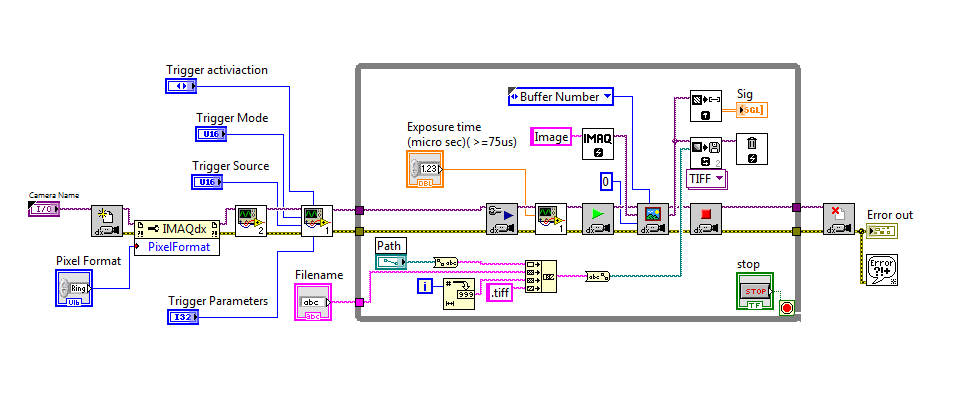
I use a F031b Pro of Guppy, which is equipped with trigger Mode in bulk. This mode I take multipule frames with an external trigger.
I want to take two image each trigger and save them. But I have no idea how to achieve this function with IMAQdx. Is that what someone had done it before and can give me a hand?
I'll use Grab or "IMAQ make image"? I will use a whileloop do twice the picture get excuated or the VI will automatically grab the two images?
Thank you very much!
Wen
Cody A., Kyle T.,.
I have already programmed a VI include the trigger mode 0 (edge triger), triggering mode 1 (trigger level) and in bulk trigger. I followed the IO camera that can show me the camera exposure time. And I found after each trigger, the camera did show twice.
Will I put the buffer number 2 if I want to use the trigger in bulk?
How to read the two images in my stamp?
Thank you very much!
Xu Wen
-
How to trigger and outputs analog and digital Outout tasks begins on a counter to start?
Hello
I'm trying to synchronize the start of a task outputs analog, a task of digital output and a task of counter. I want to start the counter to serve the master trigger and analog and digital tasks to synchronize his departure.
I guess I need something like:
analogOutputTask.Triggers.StartTrigger.ConfigureDigitalEdgeTrigger ("?", DigitalEdgeStartTriggerEdge.Rising);
digitalOutputTask.Triggers.StartTrigger.ConfigureDigitalEdgeTrigger ("?", DigitalEdgeStartTriggerEdge.Rising);
analogOutputTask.Start (); Slave 1
digitalOutputTask.Start (); slave 2
() counterTask.Start; n / / master
Where? is a string specifying a command source for the beginning of the task of the meter. However, I can't find what this string. Any suggestions?
Thank you!
-Jon
Just FYI, the solution to this problem as well as some other ones is encapsulated in a short example .NET, I created. It is on the Web site of EITHER:
http://decibel.NI.com/content/docs/doc-15500
This project shows how to synchronize all your analogue/digital outputs through tasks and forums in terms of synchronizing Calendar and start clock.
-Jon

Maybe you are looking for
-
Unknown network on HP 2000 controller - 2c29nr laptop, running windows 7
HP2000 - 2c29nr laptop, downgraded to windows 7, and now I can't connect to the internet. There are now 4 that unrecognized devices. I looked everywhere for the drivers, because if something goes wrong he says I need to do, but the computer can not
-
HI -. I recently installed a R7000 Nighthawk, but he needs a range extension to access certain parts of the House. The R7000 is rated AC1900. I think buying the EX6150 range extender, which is rated at AC1200. Is it still compatible with the R7000, b
-
I have problems with my Pro 6. I was never able to get my Raid 5 storage for make sense. Is less than the correct figure of total storage? I thought that must be read higher than 10 TB. Am I missing something?
-
Setting up Sony Alpha 6000 to transfer files on my Mac
I downloaded the software of automatically importing wireless Sony. I connected my camera to my computer via the supplied USB connector. I'm then in an infinite loop, which tells me that I can not complete the installation because my Alpha6000 is con
-
I have I can not reinsttall printer drivers or uninstall the old that I can't find. Help!
I have windows xp and a hp color laserjet 2600n. He worked for many years, but now I get an error of queue and cannot use one of the microsorf office programs. Error prevents from print or print previews. I tried to go into the printer and fax folder