trigger delay
I have a digital trigger switch that is bound to a module OR. How can I know the amount of the delay from the trigger to the module or?
Yes.
AKA 0.00000305 seconds of 0.02 seconds trigger duration.
AKA 305usec off 20000usec
AKA 0.305nsec off 20000000nsec
It is up to your application if it is negligible. If the nuclear reactor will explode in 2 microseconds, unless this digital trigger closes its first down, you watered. Otherwise, good to go.
Nothing is instant, including all input signals you have. The propagation delay is on the front and down the signal, then the length of signal will always be 20ms, it will simply be moved by the delay of 3.
Tags: NI Software
Similar Questions
-
Hi all
play with a digitizer PXI-5124 in a case of PXI1042Q with a PXI8110 controller that runs labview 2012 (latest updates) with the latest version of the driver NIScope.
I put in place an acquisition of off-delay (by assigning the triggering delay, for example 20us) which works very well (I can tell by the signal I get delay control works correctly), but the data returned in the info wfm cluster (using the 2D version of niScope I16 Fetch) does not have this delay.
Description of the relativeInitialX within this cluster indicator indicates "is the time in seconds between the trigger and the first sample in the acquired waveform" but its never to return something around 1E-9 independent of trigger delay. Surely the relative initial x should reflect the triggering delay?
I'm doing something wrong?
Thanks for your help!
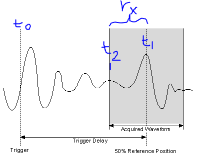
So, I made a screenshot of the image in the section "Trigger Delay" link I sent you.
Meaning of the symbol:
T0 = original moment of relaxation
T1 = time to trigger used in the acquired record (t1 = t0 + TriggerDelay)
T2 = time of first sample in the record of the acquis.
RX = relativeInitialX = t1 - t2
Response to previous reviews
«I understand what you're saying - so basically, if I want to know the delay of my trigger for the first sample in the record, I just add my delay time value to the relativeInitialX.»
- Close, the delay of the original trigger (t0), for the first sample in the record (t2), would actually be TriggerDelay-relativeInitialX
«.. . Nowhere does graphically describe where is the relative value of initialX real. »
- Right, relativeInitialX is not a timestamp, so it is not a place on the timeline, it is the difference between two timestamps (t1 and t2 above), where the relativeInitialX name.
"The trigger"record"is the straight line in the Middle, so expect relative to - 1/2 initialX record length?
- Almost correct, because the reference trigger is relativeInitialX to the position of 50%, will be the time in seconds for 1/2 the record length. (i.e. If the registration has been long relativeInitialX, 2s = 1 s). RelativeInitialX will always be the delta time between the trigger (t1) and the first sample returned in the record (t2).
- For example using the picture above: If t0 is 10 sec, Trigger Delay = 3 sec, SampleRate = 1 kHz, = 1000 record size. This means that t1 = 13 s. Our record is long of 1s (1000 points to 1 DC between each = 1 s), if t2 = 12.5 sec. If away from all these moments are absolute time, as the timestamps. So relativeInitialX = t1 - t2 is 13-12, 5 = 0.5 sec.
- As a side note, the reference position should not be 50%, you can configure to between 0-100%.
Time not yet discussed record attributes
I don't want to make you more confused, but there is another useful attribute in the waveform info that we've not yet discussed and its AbsoluteInitialX. Starting from the NOR-SCOPE help file:"absoluteInitialX is the timestamp of the first sample of recoveries in seconds..." "So, using the above image, absoluteInitialX = t2.
I hope this helps. If a part is still not clear, let me know.
-Nathan
-
How to synchronize or trigger OR-DAQmx devices in LabView
I'm using LabView 2009 with a cDAQ-9174 chassis which includes an NI 9263 analog peripheral and an NI 9222 analog input device. I learned in the examples that I can synchronize the devices at the same sample rate. But I'm looking to sync devices such as the exact moment where I start to acquire input channel 9222, the 9263 begins to generate output. Secondly, I am interested to know when to use just this material, is it a way to very precisely to trigger a device turned off each other with a certain delay. So in summary I am interested in two behaviors:
(1) to synchronize an output channel 9263 to an input channel 9222, such as the beginning of a measure of analog input 9222 triggers a 9263 analog waveform output. and,
(2) have the analog output of the 9263 beginning for example EXACTLY 100 samples (provided that the sampling rates are synchronized) after that the 9222 starts to collect data. In other words, a trigger delay.
I guess that preference for it in hardware such as no software delays occur. Is this possible using these devices? Or do I need an external synchronization mechanism?
Thank you!
Hi tzoom84,
Back to your original question,
(Make 1) and (2), I don't think you should use counters.
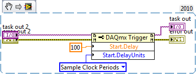
Shipping example LabVIEW 2010\examples\DAQmx\Synchronization\Multi-Function.llb\Multi-Function-Synch I - AO.vi is probably a good starting point for 1). (Possible problem: If you use several engines timing to HAVE at the same time, the hypothesis of this example that the task of the AI "AI/StartTrigger" is not valid.) If this proves to be a problem, you may need to replace the name of Terminal get with device Prefix.vi with the trigger DAQmx > Start.Term property and add a call to the reserve of the task.)
For 2), add the trigger of DAQmx > Start.Delay and trigger DAQmx > Start.DelayUnits properties of the task of the AO:
If you really need to use counters, you can do without the NI 9401 using cDAQ1/_ctr0 by cDAQ1/_ctr3, which are internal channels: How to internal access on any device DAQmx?
Brad
-
5681 calendar view to 'reach '.
I do turn into some unusual problems, understand the time to sample the 5681 scope mode.
aid is of great help. Thus, a few quick questions, assuming a capture internally triggered 300mS RF burst with a portico at 50 to 250 ms is desired using 200 samples by default is desired.
I put my capture time to 300mS I appear to trigger on the correct side.
Why apparently do more than 300 ms in my capture? What is the sampling frequency of the 5681? What effect does changing samples by capture or the duration of capture has on the sample calendar?
Protection against noise of the internal trigger is anywhere from 1 to 10 samples. One is no noise immunity. The first sample that rises above or below the threshold is triggered. If we define 2, you need two samples above or below the threshold to trigger. If a sample to survey/falls but the following does not work, we only fire and start waiting for the trigger. Because we now need two samples to trigger, we start to collect data about 14 microseconds later. If we want to get these samples back, we put the trigger delay to-.014ms. The same logic applies for higher amounts of protection against noise.
-
I am trying to acquire data using a PCIe-6361 with LabWindows/CVI 8.1.0 (with DAQmx) on a Windows XP computer.
It is analog, sync data with a digital trigger signal, and I have the data entering ai0, with the trigger going into PFI0. Right now, the trigger is configured as the trigger for the start, with the unused reference trigger.
First question is: what exactly is pretriggering? I tried to read the various messages, and the help section is less useful. It seems to be data acquired before the outbreak of departure.
I need to configure the system behaves like an oscilloscope, with a delay of release after. That said, the trigger pulse comes and then the system wait x milliseconds and then acquires the data.
Before trigger samples are unique to reference triggers. Essentially a reference trigger is a trigger of 'stop', where you have X samples to acquire before the trigger occurs and after purchase.
If you want a delay from when the trigger occurs to when you start to get data, I recommend using a trigger to start. There's a Start Trigger Delay property that will allow you to wait X time elapsed of the trigger in when you start getting data. The delay is derived by counting the graduations of the time base clock of sample I (100 MHz base time by default, which gives a resolution of 10 ns).
The relevant functions in the C API to delay the start of the acquisition are:
-DAQmxSetStartTrigDelayUnits(taskHandle, DAQmx_Val_Seconds);
-DAQmxSetStartTrigDelay(taskHandle, data float64);
Best regards
-
I use a multimeter PXI-4065 with MS Visual c# .NET 4.0 and NOR-DMM. I have a test that requires some sort of closed feedback loop and I need to take readings of voltage with an interval of every 5 ms or better (software controlled) DC for a duration of 1 second. It must be controlled so that the application can set a second parameter to the suite, IE software. I can't use a multipoint measurement function. I have read all the documentation of NOR-DMM on the opening time, settling time, etc. and adjusted my function to read the 4.5 figures, no sedimentation time and a discrete value of 0 for the trigger delay (accuracy is not very important... I need speed here). With the caveat agree that a RTOS could be better adapted to do this, if time and money were no object, I need to make it work with what I have now.
I inserted a measure of time time/arrival departure before and after the call to the function of reading (using DateTime.Now.Ticks; 1 graduation = 100ns) and I'm in a position approximately 30 m even with General treatments, I can't believe it should take as long to process this function with all the stuff on the meter power off delay. Am I missing something? My NOR-DMM function calls are as follows:
...
...
PXI4065_Session1.ConfigureMeasurementDigits (DmmMeasurementFunction.DCVolts, 300, 4.5);
PXI4065_Session1.trigger.DelayAuto = false;
TimeSpan triggerDelay = new TimeSpan (0);
PXI4065_Session1.trigger.delay = triggerDelay;
PXI4065_Session1.trigger.source = DmmTriggerSource.Immediate;
PXI4065_Session1.Advanced.SettleTime = 0;
measuredReading = PXI4065_Session1.Measurement.Read ();...
...
Help, please!
Hi mdbeaster,
Could you please check whether the following suggestion by experts of the NOR-Dmm driver is useful.
Quote
'Play will be called implicitly initiate and then pick up, but the way that the client is to set up the device, it is necessary.
Multipoint could be used in this case, since the customer is not actually reconfigure the DMM, they are just reconfigure something else based on the measurement of dmm. The customer needs to use throw and fetch the multiple instead of read. They then pick up all available steps and use just one more recent for their calculation. This should allow them to get under this requirement of 5 ms (I got it for less than 1 ms with no calculation).
A better way is to use multipoint with software triggers.
This ensures that the client does not receive a stale measure and use these stale in their adaptation of all data which.
(1) configure mode/range/settle time
(2) setup for multipoint with enough points for the period of 1 second
(3) configure the trigger to the software
(4) Insider
(5) in a loop:
(a) send software trigger
(b) fetch
(c) use as you like.Thank you best regards &,.
Ramanantsoa
-
lsdaq does not list my PXI-6289 (Scientific Linux 5.5)
Hi, I'm new to both NOR and Linux, but I just got to get our (PXI-6289) M Series DAQ to work. The computer running Scientific Linux 5.5 and DAQmx both DAQmx Base already installed. It is connected to the chassis PXI-1036-controller PXI-8336.
But lsdaq can't find anything:
$ lsdaq
--------------------------------
Detect of National Instruments DAQ devices
Find the following materials:
--------------------------------Even if everything seems connected otherwise:
# nilsdev
OR PXI-6289: "Dev1".
OR PXI-6289: "Dev3" [absent]
OR PXI-6289: 'PXI1Slot6' [absent]# nipxiconfig-l
List of identifications:
Frame 1 (PXI-1036)
Slot 1: PXI - MXI-4 kit
Slot 5: PXI-6289 (PXI5::12:INSTR)Any ideas on what I might try next? Any other information that might be useful for me to post?
Thank you!
Hello world
I would like to clarify some things in case there was any confusion.
DAQmx 8.0.1 was released for Linux [1], but my recommendation for the PXI-6289 is to use DAQmx 8.0.2 [2] and not DAQmx Base (the latest version is now 3.6 [3]). Both DAQmx 8.0.2 and DAQmx 3.6 support the 6289, but DAQmx offers better performance and exposes the full set of features of the material. DAQmx Base performs all types of measure, but does not implement the less popular features (like the trigger delay, delay clock sample, routing subsystem, etc.). The best time to use DAQmx Base on Linux is hardware DAQ USB because it is the only rider OR that supports these devices.
Finally, about the release of the list: ask the command nilsdev DAQmx what material he has under his control and lsdaq done the same for DAQmx Base. As with any OS, that a driver can associate with each device and DAQmx will anticipate DAQmx Base when enumering devices since it has full support for hardware. Thus, nilsdev seen the 6259 since DAQmx had taken possession and lsdaq reported nothing since there is no connected USB devices.
[1] NEITHER DAQmx 8.0.1 for Linux
http://Joule.NI.com/nidu/CDs/view/p/ID/1194/lang/en[2] NEITHER DAQmx 8.0.2 for Linux
http://Joule.NI.com/nidu/CDs/view/p/ID/2322/lang/en[2] NEITHER DAQmx Base 3.6 for Linux
http://Joule.NI.com/nidu/CDs/view/p/ID/3434/lang/en -
How to use NIHSDIO_ATTR_DATA_ACTIVE_INTERNAL_ROUTE_DELAY?
For simplicity, I have my generation than active events of the session data exported to PFI0 and I Start Trigger of the session with my purchase configured to monitor PFI0. However, due to the RTD, I have a lag of calendar data.
The help document specifies an attribute "NIHSDIO_ATTR_DATA_ACTIVE_INTERNAL_ROUTE_DELAY" can be used to generate a trigger delay. In addition, he says:
You can set up the data event Active delayed as a source for any trigger of acquisition by manually entering DelayedDataActiveEvent as parameter triggerSource .
I have no problem by assigning to the attribute, but I was not able to find how to USE the event active data 'delayed '. It doesn't seem to be a signal that I can export to PFI0, or it seems to be a place that I can configure start trigger acquisition to watch.
I use niHSDIO dll revision 1.5.3
Hi broke,
There are two standard methods for eliminating the round-trip time of your measurements:
- You can use the DelayedDataActiveEvent signal to start your acquisition. Using this, you can set the number of clock cycles sample to delay your purchase to account for the RTD using the internal travelling time attribute. I would like to look at the example of RoundTripDelayElimination to see what it looks like in C coding. Here you can find the default example: C:\Program Files\IVI Foundation\IVI\Drivers\niHSDIO\Examples\c\Measurements\RoundTripDelayElimination
- Alternatively, you can wire the DataActiveEvent through your ESE and the Commission of HSDIO physically. This would give the DataActiveEvent the same as the data itself round-trip delay.
Looks like you're on the right track with the DelayedDataActiveEvent, I would like to know if you have any questions about the examples or have problems by eliminating the RTD. Thanks for posting and have a great day!
-John
-
How to delay a PXI-5122 trigger before routed to string of PFI
Hello world
I use a PXI-5122 in a PXI chassis. I want to synchronize with two external devices. The first will send a trigger (with a 10 Hz repetition rate) for PXI-5122. Then PXI will generate a trigger (with a constant delay) in the second.
It seems that I need to generate a trigger, then export this trigger to PFI 0 line, but I do not know how to delay triggers with a timeframe of 4µs. I read that there is a slight delay between a trigger on the PFI and the first sample. And the length of the cable is also an important factor to consider.
Could someone give me some suggestions?
Wednesday,
Thanks for the drawings, that helps a lot! Somehow, I see this work (how to set up the scanner):
1. set up the record length to be 12us (4us trigger samples, 8us after outbreak). If the sampling frequency is 100 ms/s, that would be a record length of 1200 samples.
2 configure the position of record reference to 33%. That's how the digitizer breaks 1200 400 samples according to trigger before triggers and 800 samples.
3. configuration of triggering immediate reference. This will allow the acquisition of trigger the moment she gained 400 before triggering samples.
4. export the "reference trigger (Stop)" to send to Device_2. This output pulse is of variable width, so if you want consistency, you will need to the Device_2 trigger the rising edge of the pulse, did not not fall m. Once 400-pre-trigger samples are acquired, this impulse will be sent, and then the scanner will be immediately habitable after initiation of sampling.
5 configure the trigger of the entrance of Device_1 (10 Hz trigger), as the 'Advance trigger' and 'Start Trigger'. This will make the digitizer wait this impulse to start sampling before the next record. We set up, the relaxation of beginning to the 1st record and the trigger in advance for all subsequent records.
This facility should allow a pretty decent timing, but please test to be sure that it will be sufficient for your application.
Kind regards
Nathan
-
Hi all
I thought that I could transfer it here because it might be a more appropriate forum. I have a bit of time pressure, so I hope someone can help me. I'm having a problem with a program that I wrote to acquire and store images from a camera to linear scan.
My camera (SUI Goodrich, 1024 pixels) is connected to a card framegrabber (PCIe-1427), which is connected via a RTSI cable to a PCI-6731 card attached to a SCC-68 (series) connector M. My goal is to drive a mirror galvanometer scanning and acquire images from the camera continuously on each scan. As the galvo scan will be the frame of an image (1024 pixels x 1024 lines).
I managed to do it (I think), as my direct purchase program works exactly as I expected. However, when I try to save the images, I noticed that for a larger number of images, the starting point of the image is shifted the same amount for each image. I'm not really sure what's going on, it seems to me that there is a delay in the use of the VI "IMAQ set up buffer" when a larger number of buffers is used, (or even 100). Is it possible that my hardware trigger does not wait for all buffers to be configured before you start to run?
I would really appreciate any idea or ideas that anyone could have on this issue.
Sincere greetings,
Gill
I fixed the problem by doing that I don't use actually 1000 stamps to save 1000 frames. Program works if the number of buffers is lowered.
-
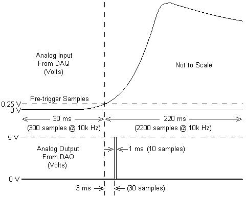
I am working with a combustion chamber and using a system of data acquisition (with the hardware OR SCB - 68) to read the pressure in the cylinder (such as analog voltage). I'm trying a pulse delayed, 1 millisecond to 5 volts of output once the pressure in the cylinder is high above 5 bar (which corresponds to an analogue voltage of 0.25 V). I would also like to record 30 ms samples before the trigger and 220 ms samples after the outbreak. The following image shows visually what I'm talking about.
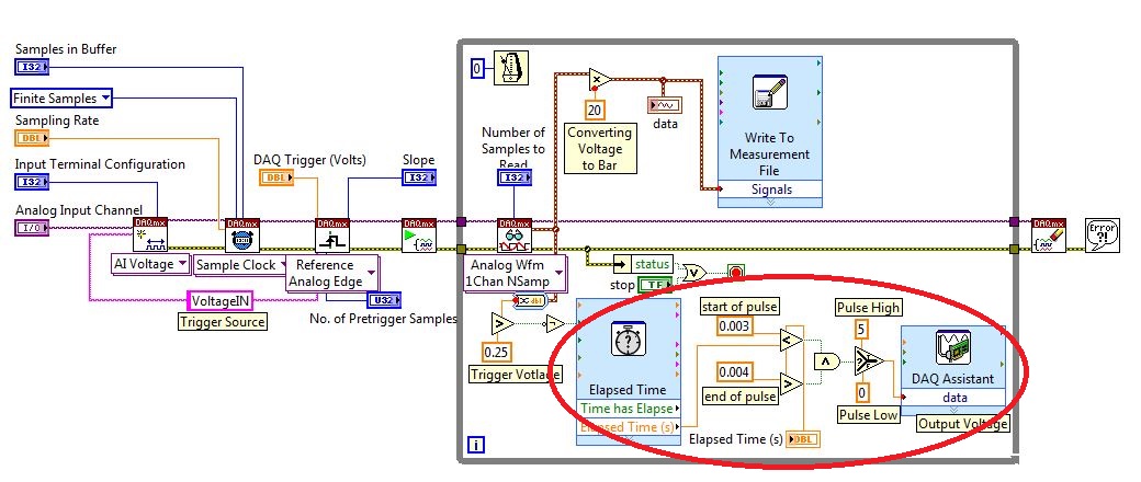
I created a LabVIEW VI (which is attached), but I keep running into 2 issues:
- When I run with samples finished after a period of time, I get error-200281which I don't quite understand.
- Using the Express VI 'Out of time' to keep time for the pulse I can not get a resolution of 1 millisecond, the pulse is not generated when I put the window between 0.003 and 0.004 seconds for high pulse (i.e. the resolution of 'Elapsed Time' seems to be too coarse).
I'm a beginner to LabVIEW sorry if my questions are trivial or my VI makes no sense, but I was stuck on this during more than a week. Any help would be greatly appreciated!
Thank you
Morgen
This isn't a good way to trigger a pulse.
Use a trigger DAQmx to send the pulse when your acquired signal exceeds 250 mV you specified.See this for DAQmx trigger:
-
redeclenchables out initial varaible on each trigger with delay
I'm trying to implement a redeclenchables generation digital pulses of the train on 6363 PCIe with LabVIEW with the additional feature of an initial delay variable.
For example:
-J' have a fixed pulse train
-After the 1st trigger, it is generated without delay
-2nd after trigger, there is a delay of 10µs
-Each subsequent trigger increases the delay of 10µs
I tried to do by writing new samples to the digital output, which include an initial delay. Since it merely controls how the buffering is managed this does not seem to work reliable with reboot and redeclenchables ouput.
Is there another way to do this using a perhaps additional internal counter for the generation of delay?
Thank you
Christoph
I would look at using an additional counter that your delay generator. There is a counter property called
Delay 'auto increment Count', which lets specify you such a regularly increasing. Here is one
DevZone article and example that should help get you started.
The idea is that the extra meter comes between your initial trigger signal and the
pulse train finish that you want to generate. The additional counter made its own triggered impulse
with time growing after the initial trigger and your finite pulse train gets triggered by
This additional counter output.
-Kevin P
-
How to delay and trigger output for redeclenchables DAQ
I make redeclenchables data acquisition based on the technique described here and that my departure point couple year I used joint comes with LabVIEW example.
What I realize now is also already done that I need to delay the recognized outbreak and output as a trigger for any other device signal.
How to make a simple diagram:
Trigger is recognized-> DAQ [which works perfect already more than a year]
-> wait 100ms-> exit the trigger [to be added]Using Windows XP edition family, NI PCI 6110
I thank you in advance to anyone interested
-
How to create a delay to a trigger function
I have a problem, I create a function delay in the timeline with a trigger.
I want my animation to play every 3 seconds until the next sym.stop and then play after 3 seconds.
EJ. I have 3 triggers in the timeline panel:
SYM. Stop (1000)
SYM. Stop (2000)
SYM. Stop (3000)
My idea is to make a delay on all triggers, like this:
SYM. Stop (1000)
Delay.Play (2000)
SYM. Play
SYM. Stop (2000)
Delay.Play (2000)
SYM. Play
SYM. Stop (3000)
Delay.Play (2000)
SYM. Play
Because I don't know how to create a jQuery function, I pray for your help.
THX
You can use these codes for the delay in your triggers
Put this code at the time 1000 in your time line
//////////////////////////////////////////////////////////////////
SYM. Stop();
clearTimeout() (eventTimer); Disable the time-out
var eventTimer = window.setTimeout (function () {sym.play(1000) ()}; 2000); / / 2-second delay can play
Zaxist
-
delay between the trigger and data acquisition
Hi, I use NI SMU-6368 as a tool for data acquisition. In my experience, I use an external digital trigger to start taking measures of a thermistor.
However, before the experience, I want to know the time that elapses between the detection of the trigger signal and data acquisition start time.
Is there a way to do this?
Here's the kind of thing I configure to get an accurate measure of time of t = 0 trigger signal to the
the actual first A/D conversion. It may be too much for a measurement of the temperature, but you should get
the right track.
-Kevin P
Maybe you are looking for
-
Store TV +: hear audio but no video playback of MKV files
Just bought a Store TV + MEDIA BOX. Downloaded MKV files that play perfectly on my PC.Part of the charge of video files up - can hear the sound but no video.Any comments would be me appreciated
-
Get my HP DeskJet 3745 printer back online.
I went into the Control Panel, go to printers etc. detailed, just clicked on the icon of the printer, but none of these options can be changed. The green market/stop-light of the printer button will continue to Flash. There is a lot of paper in the t
-
SYSTEM WILL NOT BOOT: error in file/window/sys32/config/sys registered: 0Xc000014c
I can not get a command code: SYSTEM DOES NOT BOOT: error in file/window/sys32/config/sys registered: 0Xc000014c I ran each sys, check, all right... SUGGESTIONS?
-
Just my Tungsten e2 from synchronization issues. It synchronizes everything fine with my PC (Windows XP) with the exception of the calendar in which it gets hung-up and runs until I have cancel out. No calendar entry is changed on my handheld or PC
-
ASA - ldap - user vpn static address
Hello! I am trying to configure ASA to assign a static IP even to some user (User1) every time when it connect to the network via the AnyConnect client. We have Windows AD and that you are using the LDAP AAA server for authentication of remote access