Trigger on position two counters
Hello
I have a request I want to compare the results of the two counters (used as station x 4). One(C#1) is connected to a system under test, and the second (c# 2) connected to a reference system. I use a USB-6221.
My main goal is to get a good synchronization between them. I want to generate a trigger for the c# 2 signal, when the system under test reaches a certain position. For example:
1 c 1 = 0 #-> Trigger for c# 2
2 c# 1 = STEP-> Trigger for c# 2
3 c# 1 = 2 * STEP-> Trigger for c# 2
................
N + 1. C# 1 = N * STEP-> Trigger for c# 2
The STEP size is variable and depends on the frequency of entry for c# 1. It is a very large bandwidth. The maximum frequency is high and it is not possible to acquire all the samples and make a software processing.
The system under test does not offer a constant speed and can count forward and backward; Thus, it is not possible to calculate a sampling rate based on the input frequency/system speed.
Thank you
KPanda
Hello
I found a solution for it. However, it is very complicated.
Here it is:
-Set the two counters: one for reference and a measurement system
Set up the counter of references as follows:
-> CI - measure of the Position
-> DAQmx calendar - clock sampling and the Source uses TC (Terminal Count - see the documentation)
Configure the counter measure as follows:
-> CI - measure of the Position
-Use Index > activate
-> Set the start and the Position after Index on max (U32) - STEP. Where (max (U32) = 2 ^ 32). The STEP is described in my first post
-> Define the PropertyNode - DAQmx for CI. Encoder.ZInput transport CANADA (Terminal Countt)
-> Define export PropertyNode - DAQmx - Singal to: CounterOutput - County of Terminal
Also set both counter the same time base.
Now, it should work  .
.
Unfortunately I do not think that I have no coding no more so I can't share it.
Paul
Tags: NI Hardware
Similar Questions
-
How to use the two counters to PXI-6280, to read and write at the same time?
Hi all
I try to use PXI-6280 counter to generate a command of step motor pulse train. The idea is to send a number done and known pulse for the engine, which belongs to a system XYZ. The point is, if, at some point, the user or the security system can interrupt the movement. If this happens (and will be... a lot), I will lose the real position, because I don't know how many pulses were actually sent to the engine. That is why I want to use the other cost to count impulses how were actually sent to the engine. I can start any tasks (generating or account), but only the first started task will operate. I met a couple of mistakes and I'm not able to find a solution.
Is it really possible to use the two counters? I've already done this in a pci system and worked without problems.
Thanks in advance,
Giavonna
Electrical engineer
I'm afraid that I don't understand your idea. Could explain you better?
Material of the series M support pointing to an arbitrary digital signals at rates (the clock must be provided from another source, for example a counter). If you want a digital pulse train finished output and have access to a counter (the two counters if find you another source for your clock, for example the subsystem "output frequency"), you must use this subsystem 'digital output' rather than the output of the counter. There should be examples in the finder of the example shows how to configure a finished task of digital output.
Now I'm generating sample clock having a single Timed material Point (the only mode accepts this mode), and configure the counter with finite samples.
I don't think not just single point NI the hardware, that's what you want. More commonly, output meter tasks use timing 'Implied', where the release date is implicitly determined by the characteristics of the pulse user-defined.
Is there a way to stop the production of only one meter when a finite number of pulses has been played in another counter?
Yes, but it's a little tricky. You can set a trigger 'Pause' on the output task, with the soruce the break being the internal release of the counter used for the task of entry. Set the initial value of the counter of entry to 2 ^ 32-N (or maybe 2 ^ 32-1-N, I don't have a system right now to check) where N is the desired number of pulse output. Together the counter event behavior for the counter edges of County switch output (this is a property of DAQmx export Signal). When the counter of entry reaches terminal, its in-house production switches, causing thus the task of output to pause. You can then stop the task in the software (you should be able to use the output of the task of entry counter event to signal to the software when the output is paused).
Now that I've written that the whole paragraph, I remember something * similar * to work around a limitation of the driver here . It is not quite the same implementation I described above, but really, you can use a meter output or a counter entry to get the same effect (it could be a good place to start anyway if you want to try this).
Is there a way to read pulses them how have been generated, without the other counter, counting impulses?
N °
Best regards
-
How can I use two counters simultaneously to pulse width measurment
Hello, everyone!
I'm new to Labview. I currently have some cDAQ9171 and width measurment with 9401 impulses. My understanding is that the 9401 was 4 meters, which means that I can use these meter separately. However I have the following problem.
1. I use ctr 0 and ctr 1 (PFI 1 and PFI5) to measure two different impulses. However, it seems that there is an interference between two counters. How can I make two counters working simultaneously and separately?
2. I first try a pulse width measurment counter in Labview signalExpress. My pulse width is about 0.4ms. However, I can't get the right result, if I choose the starting edge is on the rise (the results always around 20ns. Only if I revise my pulse and pick the starting edge is down, I can get reliable results.
I'm confused about these issues for about 3 weeks... Is there someone can help what can I do with that?
I have attached a simple vi...
Thank you very much!
-
trigger to concatenate two fields in a table
Hello
I'm trying to concatenate two columns in a table and add to the third column in the same table, all the columns are
numbers, I want to write a trigger that is after insertion to do this... does anyone know how its done...
Thank you very much
JessicaHi, Jessica,.
Welcome to the forum!
Do you really need to store this concatenation? How you get these results in a normalized database is to store the numbers separately and comnbine them, when necessary, in the queries and reports. You can use a view to avoid repeating the same coiding over and over again.
If you really want to store the value, use a trigger INSERT or UPDATE BEFORE , like this:
CREATE OR REPLACE TRIGGER     table_x_biu
BEFORE     INSERT OR UPDATE
ON     table_x
FOR EACH ROW
BEGIN
     :NEW.column_3 := TO_CHAR (:NEW.column_1)
                || '-'
                || TO_CHAR (:NEW.column_2);
END;
I'm confused about your specific needs. Concatentaion is possible for strings.
If colonne_1 and column_2 are numbers, the trigger above will make string versions of these numbers, concatenate them (with a hyphen between them), and put the results in the column VARCHAR2 column_3.
So after this statement:INSERT INTO table_x (column_1, column_2, column_3) VALUES (1, 2, '9-8');the new line will have column_3 = 1-2» (In this case, there is no point in explicitly implemented column_3, because the shutter always sets the value based entirely on colonne_1 and column_2.)
If you need more information, post CREATE TABLE, INSERT and UPDATE statements and that you want the table to contain after each INSERT or UPDATE.
-
How can I use two counters to capture a pulse ttl for a specified time
Configuration: Card counting 6062 PCI w / BNC 2121 Board running under LV 9.0 PerkinElmer Avanlance Photodiode (SPCM-AQRH-13)
I searched through the forums and fell on the theme of framing an image while collecting signals from a source for a specified time.
The example in terms of falkpl in 2005:
"
Dismal Hello,
I'll try to point you in the right
direction to start coding the application, but do not forget my
suggestions have to be modified to your specific request.For
the task output redeclenchables finished meter you need to
your counter seconds in this application, I suggest to take a look
in the Finder example in LabVIEW ('Help' are examples) and less
DAQmx hardware entry & exit"" generating digital impulses. Here,
you will find some Gen dig Pulse - Retriggerable.vi. You can use this for
Create your door 4 pulses ms it's over (not a pulse train) and
redeclenchables (for each time you go to the next step.In
regards to the configuration of the first counter, there are several things to
consider, and I can offer initial help to get set up. You
in-house allows to route internal CTR1 (4ms of pulse) output for your CTR0
Door to measure only during the time. Here are additional
Info to do this in LabVIEW. The source of your task of edges ABOVE County
will be the TTL signal you are measuring and counting. It comes
on the PFI line that corresponds with CTR0 Source.When
you make a measurement finished with CTR0, you will take only heads while
the door is high and your source has a rising edge. You can set the
measure over to start on a trigger, which is not clear in this
for example, that you have identified. Since you know that you have a finished 4ms pulse
time to measure, you can set the duration of your measure
as a result.I found this
Forum which may help some, but the coding is
textual. I hope this can give you a good starting point for
programming. -
Reversal of direction insofar the count frequency (range, two counters)
Hello
is it possible to use the meter entry B (USB-6210) for reverse metering periodically (for a subtraction of the dark count) during the execution of a measure of frequency uses the two meter, wide range method? Or is the walk back is possible in application count edge because what matters is the active edges of counter entry receives?
Thank you very much!
Michael
Hello
now I understood. No, he isn t possible with the frequency measurement. You must use anoterh meter.
Best regards
Andrea
-
How to build square 3 ph pulses and use them to trigger the two analog inputs.
Task:
1) generate continuous 1 Hz ms 45 pulses on three lines of output offset 120 degrees.
Other neighborhoods, three phases (three outputs) 120 degrees out, but instead of sine wave should be a volt 5ms 45 along with a second ground pulse. I need these impulses to control an external circuit. The tolerance of 1 Hz is loose, but 45 ms must be at 100 us.
(2) measure (trigger) two independent DC voltage over 45 ms 50 ms after each front (leader) amount of each pulse. 45 to 50 ms must be 100 us.
Other neighborhoods, begins each measure 45 ms for the DC source #1 and 50 ms for the source DC #2 after opening (rising edge) of each pulse for total of six measurements per second 1 (by 1 Hz cycle).
(3) an analog output must provide ongoing (to be booked) negative DC voltage to be used as a source of supply for external circuits.
I timely when I can generate the 45 Hz by using CO (0) 1 ms pulses continuously and the trigger I (0) on falling edge. I (0) is hard wired to triggering I (0).
How I do HAVE another (1) and two other lines (two phases) and link them to HAVE (0) and HAVE (1)?
Equipment: LabView 8.6.2, PCI-6221 (37-pin)
Hi behappy.
Thanks for posting and welcome to the forums EITHER! I think we can get what you need with the variety of the 6221 37 pins:
(1) our machines of the M series have 2 counters, so you cannot generate all the impulses of 3 of these alone. A solution would be to use outputs digital correlated.
Unfortunately, the 37 pins 6221 has only two IO digital correlated, so you should use a strange mixture of digital meters and IO to implement three impulses. It would still be feasible - for example, you might use a counter for a time base for the digital i/o lines and the other counter to the third output pulse. You would have to match the beginning of the two counters to ensure the phase of your signals.
2) there are essentially two parts to this question, so I'll try to split:
(i) combine the three impulses together to generate a single sample signal out of. I think this would be doable on a different set of M with a higher number of digital I/o lines correlated using change detection (see the user manual of M series). However, at this stage, we are just out of digital lines correlated to use, and I don't think that's possible on the 37 pins 6221.
If you use the 6221 37-pin, which you will probably need to do is to provide your own external circuits OR three pulses together.
(II) get the 5 ms delay to enjoy your second channel. Since you have already discovered that you can sample the falling edge of the digital signal for the delay of 45 ms, you would just add another delay of 5 ms before taste you your second I. You should be able to do this by setting the clock to convert DAQmx frequency (5ms corresponds to 200 Hz). The clock to convert, it's what actually sampling data (keep in mind that the boards of the M series are multiplexed).
To do this, simply use the property calendar DAQmx node, then select: more > converted > rate.
(3) this one is easy - we have not yet used all channels of AO.
So the 37 pins 6221 is a little less ideal because you have not enough correlated digital i/o to make the generation of pulses or change detection - but he has yet to do the job if you can combine the three impulses yourself outdoors and don't mind not using the additional counter to generate the third impulse.
I hope this helps, if you need any help to find relevant examples, please do not hesitate to post in return. Thank you!
-John
-
How to run two 'County of buffered edge' using two different counters at the same time?
Hello
I try to use two counters at the same time count the TTL pulses for a fixed period (lets say 10 ms). I have the card PCI-6251 and PCI-6601. I am currently using PCI 6601 as counters and running a self updated the ' stamped edge County - reset.VI. Here, I have attached my VI.
Now, during the execution of this VI, I get an error saying "error-200251 occurred at Task.vi:4 DAQmx Start" and the possible reasons are, "measures: no USB or DMA channels in loose ends are available.»
Either stop other tasks which might be using these resources or are considering changing your mechanism for transfer of data to the interruptions if supported.
Device: Dev2
Task name: _unnamedTask<80>. »
What I realized is I'm trying to use two buffers for two meters with ten samples each and this is probably not allowed. I don't know how to solve this out and bad looking for your suggestions.
Thanks in advance.
Hi all
I found a solution too. This is the VI updated the "County of edge stamped" which can simultaneously run two entries-meter using a single source of door and it also uses the DMA and interrupts to save two pads.
Have a nice weekend.
-
Double counters in Signal Express with a USB-6229
I have a USB-6229, which I'm running via SignalExpress, and I am trying to simultaneously record two inputs of meter. However, it seems that he has trouble to add the second channel. When I add the first string via signals acquire > DAQmx Acquire > counter entry > Position > angular and select ctr0 channel, he (correctly) lists PFI8 and PFI10 as inputs of channels A and B. However, when I add the ctr1 channel to the same task (via the blue and the button "Add a channel"), he still lists the same PFI8 and PFI10 as input.
On the other hand, if I first add ctr1 then add ctr0 Secondly, it lists PFI3 and PFI11 as A and channel B for the two entries of meter.
How can I get the two counters operating independently?
Thank you
Josh
He realized that I can't run two meters of a single task in Signal Express (unlike, say, two analog inputs). Once I added it as two separate tasks, everything works fine.
Now I have problems of synchronization. Looking through these tips and documentation, it seems that I will not be able to fix this via SignalExpress, so I continue in LabView. I'm having some problems with it, but I'll post in a new thread here.
-
Generate impulses to drive an instrument AND trigger some HAVE (the S Series DAQ)?
Hello
I use a PCI-6122 (with LV 7.1 and Windows XP). I'm generating a TTL pulse with one of the counters on the Board (from 0). I need to use this momentum to drive a shutter and also as a trigger for data acquisition (HAVE). Is there a way to "split" the output so I can receive TTL pulses to two simultaneous different terminals, for example to "CTR OUT 0 ' and"PFI 3"? If not, could you please explain to me, or direct me to the equipment, on the if (and how) I can synchronize the two counters in order to achieve the same thing?
Thank you.
Never mind... I figured out how to generate both synchronous impulses go both counters using a common trigger: I use a pulse generated from a digital lines (DO) that I'm physically routing to the CTR terminals 0 DOOR, i.e. PFI 9 and CTR 1 DOOR, i.e. PFI 4,. I am attaching a capture in case it is a help to someone on the other screen.
-
the use of two meters: one for the generation of regenerable impulses, one as a counter
I'm new on use the counters. I use an NI PCI-6110 multifunction data acquisition card. I want to count a digital input (on the connector of the PFI 2) pulse and also using the entrance to trigger another counter to generate impulses. So I configured the first counter (task 1) to generate digital pulses with PFI2 as a source of relaxation and redeclenchables award; and set up the other counter (task 2) to count the number of edges of the digital signal with.... But after the two tasks began, the first task was an error 50103 (or the possible reasons: NI Platform Services: the specified resource is reserved.) The operation could not be performed as indicated.) The block diagram is attached. Thank you.
Your Board uses very-old-in-electronic-standards-DAQ - STC a smart meter that requires a little secretly * two * counters work together to make a finite pulse train. He is not actually secret if you read the right parts to the right documentation, but it's not hard to miss if you are unsure you should look. It has been a while since I've done a lot with these counters, but I have this nagging thought that they may not support redeclenchables finishes pulse train generation at all. I would caution you to at least check this.
In any case, it is the reason for the error. The finite impulse generation task uses only the counter that you specify, but there was also this one to help. A couple of new generations of smart meter (NOR-TIO, DAQ-STC2) continues to have this limitation, but the * more * recent it is no longer made.
X series boards use the chip "NOR-STC3" that give you 4 programmable counters by the user instead of 2 * AND * everyone can generate pulse trains finish without using a help desk. You may want a pair of them upward with your 6110, assuming that you need simultaneous sampling analog 6110's capabilities.
-Kevin P
-
Repeating the trigger with Start.Retriggerable
I have a DAQ PCI-6259 (M-series card) card I am programming with DAQmx. I would like to know if there is a limit in terms of how close together you can use Extensible triggers. I intend to use a frequency of internal clock to 1us. An asynchronous external TTL signal will be used to trigger a finite sequence of digital output of the 6259. The finished digital sequence is 4 samples of long, so it will take 4us. The edges of the asynchronous trigger will happen on every 100us. I intend to use the property Start.Retriggerable = TRUE trigger so that I can repeat this generation 4 sample every time the external TTL signal is received.
Is 100us too close together? Is there a limit to how closely together, you can repeat a hardware trigger when using Start.Retriggerable = TRUE?
Is it possible to know if my card PCI-6259 even supports the property trigger Start.Retriggerable?
100 US will be very well (time to rearm is the order of a tick or two, 10 timebase s ~ ns).
However, the M series supports digital output directly redeclenchables not. Instead, configure a redeclenchables counter finished output to generate impulses 4 to 1 MHz (this example uses two counters embedded M-series). Use the output of the internal counter as the sample for a task of digital output clock continuous who will repeat your 4 sample sequence.
Best regards
-
How can USB-6210 I synchronize two channels of ctr
Hello
I use LV 8.5.1 and NI USB-6210. A small application I want to generate two different impulses with synchronization but simple starting point. When I configure a task with two channels the second channel configured always starts a ms later. But, if I configure both channels in terms of frequency, they start synchronously.
My idea is bad in general? The DAQmx part is fixed.
Thanks in advance
Hi there, too.
the release of the finite pulse trains, to two meters for each task. Therefore, your application will be the first impulse using two output counters and then to exit the second impulse using the two counters.
Like the USB-6210 don't not have outputs DIO correlated, you'll generate two infinite pulse trains (which can be started at the same time throug a trigger of arms) that you explicitly stop before the start of the second pulse (using the DAQmx abort task from a parallel loop), or upgrade your hardware at least a USB-622 x card series and a digital output model... Alternatively, you can use the PCI-6602 counter card and use a counter to Gate two others doing an infinite impulse train uses a relaxing break...
Synchronization of two meter in NOR-DAQmx tasks
http://digital.NI.com/public.nsf/allkb/BB7AE2D12BB04CBE862574FA005D3826?OpenDocumentUsing a counter to generate a redeclenchables Train digital pulses with a PCI-6602 and DAQmx
http://digital.NI.com/public.nsf/allkb/4A9AF19480E50C6D862571B70058142A?OpenDocumentSeveral counters on the same card with a single trigger pulse
http://digital.NI.com/public.nsf/WebSearch/CE99A0B2A9048A2A86256C630062F550?OpenDocumentBest regards
Sebastian -
How cascading 2 counters for 64-bit timer?
I work with the PCI-6225 card which has several counters. I configured CTR0 to 20 MHz. I get the CTR0 time by calling the OR-DAQmx C function 'DAQmxReadCounterScalarU32' to get the number of frequencies and then by dividing the number of frequency of 20 MHz for a time value. The maximum time value that may be getting is that of 214.7483648 seconds (2 ^ 32 / 20e6). I want to stunt/link two counters (CTR0 and CTR1) to get the frequency of 64-bit values. To be clear, CTR0 configured as CTR1 configured as 32 byte MSB and LSB 32 bits so that whenever CTR0 reached maximum values and "roll" then CTR1 would be incremented by 1. How can I do this using the C-NOR-DAQmx features?
Thank you
Ian
Hw do will be more reliable, but here are two possible ways to approach it in sw.
1. There is a DAQmx property with a name similar to "Terminal number reached" that I have used in LabVIEW but do not know the underlying C syntax. When you query this software, it will return a true once, is reset to false. I'm sure that he will return a true even once on the * following * the event rollover, but you would be better double-check me on that. Not knowing your entire application, I guess you will probably need to be prepared to manage several inversions.
2. in certain applications, rather than establishing a measure which follows the cumulative time, you can configure the hw to measure periods and then take a NAP in sw to get your 'timestamp '. Unless an individual interval could exceed 200 + seconds, you can just do your accumulation of software with a 64-bit data type.
Technically, you can even do both. Do a measure 32-bit intervals hw, do a query of software for the event of tc, accumulate intervals & counties of reversal in a 64-bit int.
-Kevin P
-
Trigger multiple channels of PFI
Hello world!
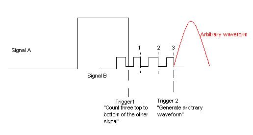
I want to create a trigger depends on two signals incoming (from external function generators) of PFI. Both are square waves, but the frequency is different. My wish is to trigger the slower from the top down as three top to bottom the faster and then generate an analog output. The picture is hopefully more descriptive than my words.
I use a NI DAQmx 6713 card. It doesn't matter if the solution is a LabVIEW VI or a C++ writes the text file. All the recommendations of good tutorials or similar is welcome. I managed to trig the arbitrary waveform after signal A or B, but I can't have the status of "County/wait three impulses."
Best regards
K. Berg
Hi K Berg,
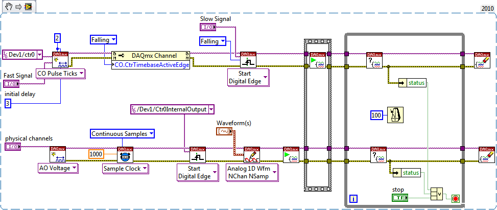
It is possible with the 6713 - you will need to use a meter of output to generate the trigger for your AO signal. Use your signal slow to raise the output of the counter. Use the fast signal for the time base of the counter with an initial value 3 delay ticks. The meter goes off on the edge of your slow signal and once that was triggered will generate a pulse after 3 ticks of the fast signal.
Best regards
Maybe you are looking for
-
What is the advantage of Apple Watch Nike + Apple Watch Sport? Vice versa?
I am looking to buy a 2 Apple Watch series and contemplating on whether to get Apple Watch regular Sport or a Apple Watch Nike +. What are the benefits of a Nike + Apple Watch Sport vs? What are the benefits of Apple Watch Sport vs a Nike +? The soft
-
Satellite Pro A40: error message - cooling problems
I have a Satellite Pro A40.I cleaned the cooling circuit (hose and cooling fan), after hearing a strange noise from the cooling fan.After cleaning the system, the error message "you have cooling shut down your computer and bring it to a service cente
-
Hi all At the moment I am trying to send a string from c# to Labview however Labview Gets an empty string, it does not notice that something is send as the listener responds simply and I checked in c# itself and here I get the right format of string
-
HP Officejet 6500 E709n wireless. Will not print Word documents or text edit.
I'm connected wireless with an iMac Snow Leopard and MacAir 10.8.2, Mountain Lion 10.6.8. I have used this system for a year, had no problems printing to date. I am able to print a .jpg attachment but nothing else, we try to print (from computers)
-
I have a Dell Inspiron mini computer laptop. As soon as you see the Windows XP screen, it suddenly becomes 2 errors. 1st error: Stop: 0x0000007E (0xc0000005, 0xf7664211, 0xf7a72724, 0xf7a72420). 2nd error: WDFLDR. SYS - address f7664211 base at f765B