- Windows: C:\Program Files\Common Files\Adobe\Bridge CC Extensions
- Mac OS: / Library/Application Support/Adobe/Bridge CC Extensions
Try to adapt the XY graph output
Hello, I'm trying to adapt to the output of a XY Chart which is (table 1 d of Cluster of 2 elements (2 x 1 - D doubles [64-bit real])). It seems that instead of having a table with two columns X, Y indexed number of persample, I want to have a table 1 in column d, indexed by X. Any ideas?
Thank you.
Tags: NI Software
Similar Questions
-
Have the value displayed on the bar graph output
I use the OBIEE 11.1.1.3. I have a question about the display of the values in the chart. Currently, if I create a bar horizontonal chart the values for each of the bars are only visible if I hover above the bar. Is there a way to display the actual value on the bar or another method to display this value without having to go.
What I want is something like this:
[http://blog.fusioncharts.com/wp-content/uploads/2011/03/column-chart-with-data-values.jpg]GoTo General properties of table-> nameplate-> show data labels and select 'Always' from the menu drop down.
What shud solve your problem -
Problems when you try to move the 3 stepper motors
Hello
I have problems when I Isaiah to compile a 3 stepper motors control program.
I have 3 steepest motors and controller (3 SMCP33 + SMCP33-EVA) nanotec.com, they also provide an example of Vi to control a motor that works successfully, but problems happen when I try to adapt the program to try to start the 3 Motors. The final application for this is going to be a Cartesian robot XYZ so finally I need to program coordinates to move the 3 Motors.
I am new to LabVIEW, so what I do is try to adapt the nanotec example to order 3 engine as follows.
-J' I assign each engine a different address, doing so that I can run each engine separately. But when I try to run 3 programs at the same time, they work but all moving them the engine (the first that has been run).
-If I try to make a sort of sub - VI is the same thing, only one motor is driven.
-Moreover, I get a warning when I try this, I have attached a screenshot of this.
I have attached the Vi and texture it to improve my description.
I woul be grateful if someona can help aport.
Kind regards.
Thanks for posting the original. By comparing the two screws immediately gives an indication of what might happen.
In the picture you posted you circled two places where you changed the address of the reader. In the Example.vi - Nanotec address of the player is connected to about 14 seats. So when you try to run the other engines in your modified program, the 12 places, you have not changed the address of the player are always preset to motor 1.
What you need to do is to divide the example VI in at least three parts. The first part initialization. The next part moves the engine. The last part ensures that the engine is stopped and made any required another stop. Each party becomse a separate Subvi. Each Subvi has the address of the reader as input. The initialization and shutdown parts are placed before and after a while loop. The movement parts are inside the loop. You can use three of each sub - VI for the three engines or a Subvi combined with subVIs move three to manage all three engines.
I can't say what approach might be better without knowing more about how you plan to order the engines - one at a time or all three at the same time, what kind of feedback is used, how management mistakes and other topics.
Lynn
-
How can I display only a part of the scale in the waveform graph
This is the first time I try to use the waveform graph, since now, I used the table of waveform.
The reason why I moved to the chart, it's that I need cursors.I have 2 problem
the first: in the diagram, the graph moves when I add a new data and the scale of the x-axis stay the same size, in the right size I always saw the new data. How can I do that with waveform graph?
Second: How do I say Labview to the day I click on the graph, I need that because when move graphic I lose the day, and to make I need to zoom out, I drag the imprecateurs.
All this must be done programmatically. The LabVIEW graphic accepts tabular data, not only as the table and the graph doesn't have the ability to retain the previous points, like the story of a graph. You will need to retain previous values and then continually update the graph with the old and new values to get a shift register "chart as behavior. Cursors should be written programmatically re of each iteration, since you rewrite the entire graph.
-
Cannot change the (visually) graph in Illustrator
I have Illustrator CS3 on Mac and I'm trying to create some graphic visuals for the work. After you have created the basic chart, I select and try to access the object > graph > design, or a Variant, but the object INTEGER from the file menu is not selectable. Even using the direct Selection tool, I can't go to object > graph > Design or column or marker. Any help?
You must first close the data table. Then, you can change the graphic attributes.
-
Micro adapter USB keeps disconnecting when I try to copy the files.
Micro adapter USB keeps disconnecting when I try to copy the files.Hello
I have a Micro SD card reader, when I insert my memory card into the reader, he comes and stays there until I try to transfer files to the memory card, or if I run a h2testw test it disconnects.
Its getting boring, I bought another card reader, but the same problem persists. I tried the drive in my computer and it seems to have worked here, but just on my laptop, I'm having problems.
Any help will be appreciated, thanks in advance!
Hello
1 did you change on your computer?
2 did you receive an error message?
I suggest you to check with the other USB port.
Method 1:
Tips for solving common driver problems
http://Windows.Microsoft.com/en-us/Windows7/tips-for-fixing-common-driver-problems
Method 2:
I suggest you to remove and reinstall all USB controllers
To remove and reinstall all USB controllers, follow these steps:
(a) click Start, click Run, type sysdm.cpl in the Open box, and then click OK.
(b) click on the Hardware tab.
(c) click the Device Manager button.
(d) expand Bus USB controllers.
(e) right click on each device under the Bus USB controllers node and then click on uninstall to remove them one at a time.
(f) restart the computer and reinstall the USB controllers.
(g) connect the removable USB storage device and perform a test to ensure that the problem is solved.
-
Try to find the extended ICA if I use a graph on a t shirt, anyone know?
Try to find the extended ICA if I use a graph on a t shirt, anyone know?
Hello
In the FAQ - Adobe Stock helps | Frequently asked questions
Adobe Stock offers licenses allowing licensees to sell products or services based on an image?
At the moment, Adobe Stock only provides standard licenses, allowing the licensee to use the images only for illustration purposes.
-
Try to install the output for bridge CC module but there is no file extensions for Windows
I am trying to install the output module for the CC bridge on a Windows system, but there is not an extensions folder in my folder of bridges CC. I've seen several discussions on this issue for Mac, but nothing on a PC. Suggestions I could use to remedy this situation? -Thanks!
To install it, please download the package such as listed in the below mentioned link and follow the installation instructions.
http://helpx.Adobe.com/bridge/KB/install-output-module-bridge-cc.html
Make sure that you have the most recent version of the bridge CC (6.0.1) installed.
Please follow it mentioned below as follows:
- Copy the folder Adobe Output Module (not the folder AOM_Package_ [OS]) in the folder Extensions of bridge CC in the correct location as shown:
- 64-bit Windows:
Go to C:\Program Files (x 86) \Common Files\Adobe\Bridge CC Extensions
- 32-bit Windows:
Go to C:\Program Files\Common Files\Adobe\Bridge CC Extensions
2. copy the file AdobeOutputModule.workspace in the folder of workspaces under the bridge CC Extensions (such location noted in step 1) folder.
Let me know if it helps.
Kind regards
Ashutosh
-
Try to install the output module - file Extensions bridge CC
Followed intsructions for installing the bridge output module, but there is no bridge CC Extensions folder in the library as suggested:
- Copy the folder Adobe Output Module (not the folder AOM_Package_ [OS]) in the bridge CC Extensions folder in the appropriate location:
Someone had the same problem and not the fix? Thank you
Make sure that you have the most recent version of the bridge CC (6.0.1) installed.
After I installed CC Br compared to the creative clouds (https://creative.adobe.com/products), follow the steps as shown in the link for help to operate the AOM.
Kind regards
Ashutosh
-
How to manage the Data Association output when no line not returned?
BPM 11 g, I use a Service to select a line in an external database in passing a parameter using a database adapter. Works fine when a row is returned. But if no row is returned (which can happen, because no match is not found on the selection based on the value of the parameter), I get an error on the composite as output data Association has return values, including integers, mapped to a data object, I defined in the process. Well, if no row is found, the integer value is empty and mistakes to try to save him.
How to handle this situation?
The specific message is:
The expression bpmn:getDataOutput('wm91AInterfaceMainCollection') / ns:Wm91AInterfaceMain [1] / ns:board is empty. An attempt to read or copy the referenced data or calculated by the XPath generated invalid data, according to the XML schema, or did not contain some optional data. Ensure that the variable result or expression named in the error message is not empty. Enable related data elements XML schema validation for the enforcement data are valid.
I must be missing something obvious here, but can't find a way to handle this. Thanks in advance!
Hey Joe,
Of course, others will be have another idea, but opt for the XSLT option for mapping your data. Using XSLT, you can check for null in an 'if '.
Dan
-
Qosmio F20-155: colors wrong when I try to use the S-video connection
When I try to use the S-video, the photo shows with wrong colors or color of Pentecost. Do I need some kind of driver?
Sometimes the photo looks like it (press the link to see)
http://www.jawally.com/VB/uploaded/6_ss.gifPlease give little assistance...
Thank you for your time
Majed
Hello
Just a question: you´re talk about the video-in and video output on your laptop, not an expansion or a USB-video output or something else card?
A machine you have respectively which model do do you have?Greetings
-
Satellite P100-286 (PSPAG) cannot connect to the TV via the s-video output
Hello
I'm trying to connect my P100 from my TV using the S-video TV output and the TV is never detected. Even if I try to "force the detection" in the nVidia control panel.
Any ideas?
Hello
Try please to find the high-quality S-video cable. I heard many years ago that some cables are wrong pinout. If you have time visit some TV expert and look for info on the S-video cables.
-
My helmet is for some time, as the eye of the terminator, glowing and speakers have not worked since. I need to plug headphones or external speakers. Whenever I try to adjust the volume when it shows just a cross symbol under the sign of the volume, where small squares usually are (see below)

Is there a way to fix this? Some other similar forums tell me to try to manually move a switch in the audio jack, but I can't seem to find such a change and the thing that seems most like a light switch, does not move.
Can someone please help?
Thank you
Your audio output is stuck in optical mode, this is the red light.
The solution is to try to insert and remove the plug a dozen times or more in the hopes of convincing making fall out of optical mode and in electric mode.
-
QUESTION: SE 2012 data display returns to the time graph each time
Hello
I have SigExp 2012.
If I try to add a data view and make a pledge of graphic style, thermometer, etc., as soon as I have the right up until it clicks, add my TC chain, the data view returns immediately to a graph time.
In addition, even if I use the graph of time, once I added the signal, it only let me see the string in a table, a chart of time or a waveform graph. Those are the only choices.
If I use a graph of time or a band of waveform graph, it does not read the signal correctly, but I can not configure the data view, the way I want it.
Is this a bug or I do something wrong?
Thank you!
This occurs when you try to change the display of a signal in its raw format "waveform".
You must convert your signals in scalar format. To do this simply add an amplitude and levels step (under: analysis > measures Time-Domain). Drag this DC signal newly converted to a new chart and right click on the graph to change the display.Honestly, I'm not sure why raw waveform signals are inherently limiting viewing functionality, but in such cases, it is.
You can also; According to the devices on which you use and the order in which you add to your DAQmx Acquire, some default signals step to scalar signals without having to convert.
See the attached screenshot and you'll see how the icons are different between the waveforms and scalar signals.
Hope that helps
-
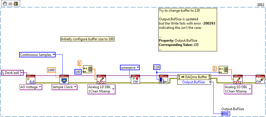
How to clear the output buffer, possibly resize and burn again, before you begin the task of output
I use PyDAQmx with a USB-6363, but I think the question is generic to DAQmx.
I have an output buffer that I want to be able to (re) write to without starting the task output.
More specifically, I have a graphical interface and a few sliders, the user can move. Whenever the slider changes, a new set of values is loaded into the buffer output through DAQmxWriteAnalogF64. After you set the value, the user can click on a button and start the task output.
In some cases the change in cursor does not require a change in buffer size, only a change in the data. In this case, I get the compalint following DAQmx as they tried writing:
The generation is not yet started, and not enough space is available in the buffer.
Set a larger buffer, or start the generation before writing data more than content in the buffer.
Property: DAQmx_Write_RelativeTo
Value: DAQmx_Val_CurrWritePos
Property: DAQmx_Write_Offset
Corresponding value: 0
Property: DAQmx_Buf_Output_BufSize
Corresponding value: 92In other cases the change in cursor requires both change in the size of the buffer and data modification. In this case, I get the following, but only after that do a few times each time increase the size of the writing.
DAQmx writing failed because a previous writing DAQmx configured automatically the size of output buffer. The size of the buffer is equal the number of samples written by channel, so no additional data can be written before the original task.
Start the generation of before the second writing DAQmx or set true in all instances of writing DAQmx Auto Start. To gradually write to the buffer before starting the task, call DAQmx Configure an output buffer before the first writing DAQmx.
Task name: _unnamedTask<0>State code:-200547
function DAQmxWriteAnalogF64I tried to configure the output via DAQmxCfgOutputBuffer buffer (in some cases, by setting it to zero or a samples, then save again, in an attempt to clear it) but that doesn't seem to do the trick.
Of course, I can work around the problem by loading data only when the user clicks the end button, but not what I'm asking here.
Is it possible to "remake" the writing of output before you begin the task?
Thank you
Michael
Today I have no material practical to validate, but try unreserving task before writing the new buffer:
DAQmxTaskControl (taskHandle, DAQmx_Val_Task_Unreserve);
With a simulated device, he made the error go away in case the buffer is the same size. You will need to validate if the data are in fact correct, but I think it should be (unreserving I would say reset the write pointer so the old buffer are replaced with the new data).
I always get errors when you try to change the size of buffer if (on my 6351 simulated). I posted some similar mistakes about the reconfiguration of the tasks here, I guess it is possible that this issue has also been set at 9.8 (I always use 9.7.5 on this computer). If the behavior is still present in the new driver, and also appears on real hardware (not just simulated), then it seems that this is a bug of DAQmx someone at OR should be considered.
I wrote a simple LabVIEW VI that captures the error in order to help people to NOT reproduce it:
The best solution at the moment would be likely to re-create the task if you need to change the size of the buffer (or avoid writing data until you are sure what will be the size of buffer).
Best regards

Maybe you are looking for
-
"Untrusted connection" when I try to open Gmail.
I've never had no problem with Gmail up to our days. I'm not quite sure what the support of Best Buy technician did fix my anti-virus, but now FireFox refuses to load Gmail Web page. He tells me now that the connection is not reliable and that it ref
-
Portege 4000 - upgrade RAM & graphic card driver installation
I'm having some trouble with my Portege 4000 for the moment. I installed XP on a disk, but will no longer have that I have 256 MB of RAM... -Have you tried 2 manufacturers but the PC133 512 is not compatible. However, my system has an IBM of PC100 25
-
my itunes will not open and there is a pop up that rpet ' cannot read itunes library .itl file ' '.
For some reason any my itunes will not open and there is a pop up that keeps saying "cannot read the itunes library .itl file ' and I don't know why it keeps coming back." Anyone know?
-
Some update were not installed in windows 8
I'm trying to update Windows 8 to 8.1 but when I try to install, showing the error. It is the Intel graphics driver. Any help please
-
How script: if (1-5 = "S/o" field) event.value = "N/a".
I amstill learn and I have a script as follows:varTotally = 0;varTotal = 0;forTotally var = 0;var total = 0;for (var i = 1; i < = 5; i ++) {}var f = this.getField ("JDCRDropdown" + i);If {(f.valueAsString=="Y)"}Totally ++;total ++;} Else if (f.valueA