Two analog inputs of synshronized
Hello
I am using PCI-4461 and connection of two amplifiers in its analog inputs (AI0 and AI1).
I need the output voltage of the two devices based on time together; This means that the AI0 and AI1 must be synshronized.
And then draw the voltage v/s time in 2 different plots. This means that I need to split signals and analyze each channel separately.
Number of samples: samples of 200,000
Do you have an idea how do?
I've used extensions on the acquisition of data PCI-4461 to select multiple channels and in control, I selected several channels.
How do I continue to get the plots?
Thank you in advance,
Kind regards
Connect the waveform 1 d array to the array of Index entry. Drag down to get two outputs. Each output wire to a graph. The index entries start automatically to 0 if you do not need to connect something there.

Dividing is done with the function of Division. You just son of the waveform in an entry and a wire to another constant.
Tags: NI Software
Similar Questions
-
PXI-6070E, how can I configure which are two analog input pins?
Hello
I'm reading 3 analog signals using PXI or 6070E simultaneously. I'm looking for on what axes correspond to what analog inputs? It's the same thing all the time, or should I set up?
For example, currently, the pines 68 and 34 are the + and - of the AI0 channel. But I can't find the rest.
Thank you.
How you are looking for the list of the pins? Look in the manual or in MAX, right-click on the device and select 'device pinouts. Ai0 is 68, ai1 is 33, ai2 is 65. The pins do not change. What changes is ending the pins to use if differential or single acquisition. For example, if you purchase a differential signal with ai0, you use pins 68 (ai0) and 34 (ai8).
-
To access the two analog inputs of two executable screws separated?
Hello world
I have two separate executable screws that need simultaneous access to different channels of the same card PCI-6229. However, it seems that this is not possible with the DAQ Assistant due to a conflict of resources? Does anyone know if it will work with the lower level DAQmx blocks? And if so, how?
If this is not possible, so if I set up a single executable to make all data capture, how would I transfer data quickly between two executables?
Thank you for your time!
-Yohan
The advantage of using the SMP library is that it works on different or local computers. In normal operation, you have two PCs each running an executable-> messaging via TCP/IP. If a single PC dies, you can just start the two executables on the same PC and it works in the same way. The only thing you have to change is of course the IP address used for communication of SMP and the map DAQ which must be in the PC running.
I don't know what HW you use, but most of the DAQ cards with 'only' a timimng engine, which means that all channels are sampled at the same pace. This could be a problem for the part of your control.
An easy option to solve all these problems (without knowing what you mean with "not many entries analog": buy a second DAQ card!) :-
Yes, it costs you more money for the DJ, but it saves development time, which, in my area, much more expensive usually then a DAQ board 1 k $.
-
How to build square 3 ph pulses and use them to trigger the two analog inputs.
Task:
1) generate continuous 1 Hz ms 45 pulses on three lines of output offset 120 degrees.
Other neighborhoods, three phases (three outputs) 120 degrees out, but instead of sine wave should be a volt 5ms 45 along with a second ground pulse. I need these impulses to control an external circuit. The tolerance of 1 Hz is loose, but 45 ms must be at 100 us.
(2) measure (trigger) two independent DC voltage over 45 ms 50 ms after each front (leader) amount of each pulse. 45 to 50 ms must be 100 us.
Other neighborhoods, begins each measure 45 ms for the DC source #1 and 50 ms for the source DC #2 after opening (rising edge) of each pulse for total of six measurements per second 1 (by 1 Hz cycle).
(3) an analog output must provide ongoing (to be booked) negative DC voltage to be used as a source of supply for external circuits.
I timely when I can generate the 45 Hz by using CO (0) 1 ms pulses continuously and the trigger I (0) on falling edge. I (0) is hard wired to triggering I (0).
How I do HAVE another (1) and two other lines (two phases) and link them to HAVE (0) and HAVE (1)?
Equipment: LabView 8.6.2, PCI-6221 (37-pin)
Hi behappy.
Thanks for posting and welcome to the forums EITHER! I think we can get what you need with the variety of the 6221 37 pins:
(1) our machines of the M series have 2 counters, so you cannot generate all the impulses of 3 of these alone. A solution would be to use outputs digital correlated.
Unfortunately, the 37 pins 6221 has only two IO digital correlated, so you should use a strange mixture of digital meters and IO to implement three impulses. It would still be feasible - for example, you might use a counter for a time base for the digital i/o lines and the other counter to the third output pulse. You would have to match the beginning of the two counters to ensure the phase of your signals.
2) there are essentially two parts to this question, so I'll try to split:
(i) combine the three impulses together to generate a single sample signal out of. I think this would be doable on a different set of M with a higher number of digital I/o lines correlated using change detection (see the user manual of M series). However, at this stage, we are just out of digital lines correlated to use, and I don't think that's possible on the 37 pins 6221.
If you use the 6221 37-pin, which you will probably need to do is to provide your own external circuits OR three pulses together.
(II) get the 5 ms delay to enjoy your second channel. Since you have already discovered that you can sample the falling edge of the digital signal for the delay of 45 ms, you would just add another delay of 5 ms before taste you your second I. You should be able to do this by setting the clock to convert DAQmx frequency (5ms corresponds to 200 Hz). The clock to convert, it's what actually sampling data (keep in mind that the boards of the M series are multiplexed).
To do this, simply use the property calendar DAQmx node, then select: more > converted > rate.
(3) this one is easy - we have not yet used all channels of AO.
So the 37 pins 6221 is a little less ideal because you have not enough correlated digital i/o to make the generation of pulses or change detection - but he has yet to do the job if you can combine the three impulses yourself outdoors and don't mind not using the additional counter to generate the third impulse.
I hope this helps, if you need any help to find relevant examples, please do not hesitate to post in return. Thank you!
-John
-
Several analog inputs seem to change any of the other (details DAQ: 2120 BNC and 6062E)
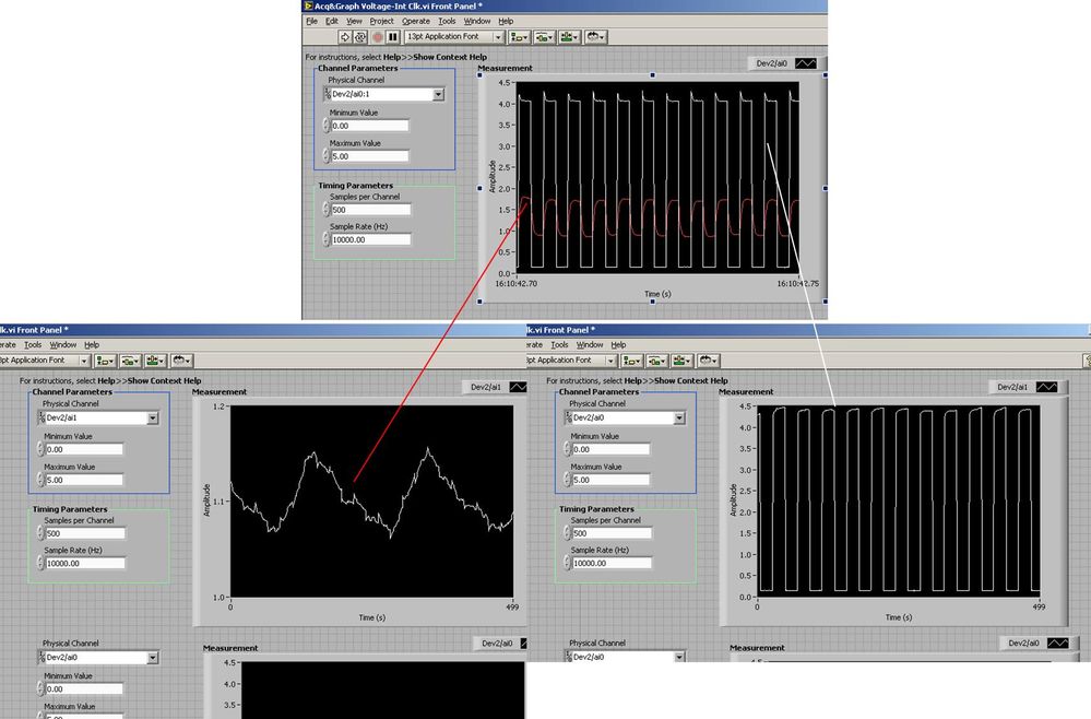
I use the BNC 2120 DAQ board connected to the data acquisition card 6062E to record two analog inputs. An entry is connected to ai0 and the other at ai1. Example vi: "Acq & graph int clk tension" has been used to measure the two entries with the value read NChan NSamp vi (channels being dev2 / ai0:1). The output is the top graph in the image. However, this seemed a bit strange to me that one of them should be modulating with a different frequency. When I record both entered individually (two in low pictures) they are indeed different since the entries shown in the top graph.

Why this would be the case, and how can I overcome this to measure the real signals?
Thank you!
The E series card takes the samples as soon as possible. Thus, for example,.
If you have 16 analog input channels but you only read of
channel 0 and 1, the map will show the channels 0 and 1 right
After and then wait 14 'ticks '. What's that little run-in
the origin of the afterglow.
I think you can get the card to wait a certain
number of ticks with a property node. I have attached a screenshot. You
can find the property node in the palette of functions >
Measurement of e/s > NOR-DAQmx > node Timing. Expand it
Property node so there's two entrances. The properties are in
Left click on the node and going more > converted >
Its properties delay units and sampling clock delay and delay that
you want.If the phase is important so the above is not the best
the option because it causes a delay in phase. So, if you need true simultaneous
sampling, then you will need different hardware. The S series is everything
simultaneous sampling.Or, rather than the Delay property and delay units, try the Rate property
find more > converted > rate.If this is not
work either, you can move the second signal source to, say, AI8 and
Connect everyone to the ground. Readings for these, but just do not take into account
the data. In this way the ADC will sag to the ground at the time where that can happen
the second string in the way so that you should not see this frequency
ghosting on the other channel. -
simple DMA FIFO reading two analog channels
Hello
I have a question on a method of data transfer between two analog inputs for a simple DMA FIFO in FPGA. The code is described here: http://decibel.ni.com/content/docs/DOC-6303. If I use this method, and I got out in a graph of my host VI, the calendar in the graph reflects the same schedule as the signals that have been entered? Or will they be phase shift between two signals?
Thank you
Grant
Grant:
Because it is not all information of timing with the signals in the FIFO, there will be no lag phase on the chart.
Hope that helps. I would like to know if I forgot something, or who does not explain very well.
Thank you!
-
Several analog inputs with different configuration differential/CSR
Hello
Can anyone tell how to measure two analog inputs with different configurations using a USB-6009?
I am aware of the syntax for create virtual channels for the channels DAQmx create virtual so I created two strings using Dev3 / ai0:1 but I would like the first string of the CSR and the second to be differential.
So far I have found no way to specify the configuration of the separate channels.Any ideas much appreciated!
Jack
JackT wrote:
I prefer to use the 'low' level vi is therefore always curious to know if there is a way to set the configuration using the their.
It should be like this:
-
Need to read a 30, 1.5 a analog input using a NOR-9205
Problem: I need to read two analog inputs with good resolution using a C-Series card. The two beaches of signal are 0-30 V @ 1.5 and 0-5 V (not sure of the current). I need to be able to read the signal 5V with a precision of mV (or 16-bit resolution).
I looked at the module-9221, which works very well with the 30V, signal, but does not have enough resolution for the 5V signal. The 9221 is 12 bits on the beach of 60V.
I looked at the NOR-9205, which works very well with the 5V signal, but it cannot process the higher V 60 signal.
If a voltage divider circuit comes to mind, but has anyone found a good solution to this (other than to get both modules)?
Well, the current should not question. The entrance of the analog device (ideally) should draw no current and everything running on the source will cross the UUT.
A 4:1 voltage divider should evolve the signal to 9205 AI as long as you do not violate the absolute maximum voltage between a pin of the device and the Earth.
-
NIDAQmx to simulate synchronized analog input from two devices of simulations?
I would test synchronized analog input from two MFDs simulated from the NI6225. I created two devices of simulated able NI6225 & Automation (M & A) and tagged the first NI6225a and the second NI6225b. M & I created a RTSI cable configuration and added both simulated devices. However, when you call NIDAQmx C functions in my test code, I get an error condition indicating that the simulations devices are not synchronized. Before continuing, I would like firstly to confirm if NIDAQmx is designed to
simulate synchronized the analog input data of two devices of simulations. If this isn't the case, then it will explain the error condition that I have encountered in my test code.
Thank you
Ian
Hello John and Jared,
If I remember well used to support the simulated synchronized devices. I ran various tests this week, but all fail. I'm going to order/install a RTSI cable and test with physical devices.
Thanks for your help. I close this post.
Ian
-
Synchronization of two inputs frequency meter with several analog inputs
Hi all
I'm relatively new to LabVIEW and I'm trying to collect data from multiple sources with calendar sync on the acquisition, but I can't understand. My problem is that I have two inputs frequency meter, an optical tachometer reading one pulse per revolution and a max flow meter machines with a 12000 k coefficient. I can't find a way to synchronize the calendar with my multiple analog inputs. I tried to first get the speedometer to synchronize with the analog inputs following the example linked here. (https://decibel.ni.com/content/docs/DOC-10785) So far every time I run it I get an error on the DAQmx read timeout or an error "several sample clock pulses have been detected" (see image). It seems if I slow the way to down to say 10 hz and make sampling rate ensure that the tachometer signal is more than 800-1000 rpm (13-17 Hz) before starting the VI then the program will run without error until the ROTATION speed is below this threshold, then the "sample Multiple clock pulses" error occurs. The code is attached below.
Does anyone know of a better way to synchronize the entries of frequency of the counter with analog inputs? I would like to have a VI that can display 0 RPM (and possibly 0 flow as well, but I think I need to understand the timing of a meter before I have add another, because it seems that I can't have two counters to the same task). Any help on this would be greatly appreciated.
LabVIEW version 13.0
Chassis cDAQ-9178 with NI 9401 for both counter inputs and NI 9205 for the analog inputs.
Thank you!
Richard
I know the error requires to restart the task at least (this particular error puts the material in a State that cannot be recovered from during execution of the task - I've been down this road before) but I'm surprised that you would have to delete and re-create the task altogether. And then I had to do this to workaround other questions in the past. It is awkward and should be considered a bug, if this is indeed the behavior.
Honestly, regardless of this bug, the way the material dealing with the situation of several sample clock edges makes measures of sampling frequency clocked essentially unusable for purposes of synchronization (in my opinion anyway) If you encounter a more slow than your sample clock rate. You are supposed to be "synchronization" of the measure, but it really no longer applies if you have to restart the task over and over again (if you must delete it or not).
Workarounds can get kind of creation (which isn't really a good thing). For example, you can configure a measure of implicit frequency to keep a buffer of frequencies and use a leader board task (source is the frequency signal, sample clock is the sample clock HAVE) to establish a correlation between the index of your buffer of frequency for singing HAVE sample clock.
Best regards
-
How to synchronize the analog input and the output of two different USB data acquisition boards
Hi all
I have two tips very different USB NI USB 6008 case, which I use to acquire the data (analog input) and a USB of NI 9263 is a output analog only site I use to route a signal (in this case a square pulse). The reason why I use the outputs analog 6008 is because I need to deliver negative tension and need the full +/-10 v range.
Looking at similar positions, I'm pretty sure that I can't use an external trigger or a common clock, I also tried to use the timed synchronization of the structures but no cigar.
I'm including a quick vi I whipped showing how the jitters because of the lack of synchronization signal. The OD of the 9263 connects to AI in the 6008 in this example.
I talked to a specialist in the phone and tols me that's not possible.

-
Hello
I have a power meter which provide the USB driver and a Labview program to get the data and NI USB-6221. The project I am currently working on the needs of:
1 acquire two signals (inputs of simple tension), pressure frequency KHz
2. acquire a flow signal, the output signal is 0 to 5V pulse, each pulse means 0.4 ml volume. So I use a voltage inflows to count impulses in certain period of time (in this case, 1 S) for water flow. ; KHz sampling frequency and the 1 Hz update rate
3. acquire a signal of engine speed. The output signal is pulse square wave whose frequency is related to the speed. I use a REIT port to measure the frequency. Sampling rate: Auto
4 give output voltage sine or square wave, I use AO do that.output rate: Auto
5 acquiring by VISA electricity meter data. Data update rate: every 50ms
Currently, all the 5 tasks work well separately. But when I put them together, some signals are beginning to hang, for example, pressure signals sometimes give nothing.
Another problem is the data record. I programmed the VI in such a way that whenever I press the button 'save start', he begins to record data and save them in a .cvs file. For some reason, I always get only the data in the first table. Coult someone help me? I download my code as follows
Hello
What I meant by open, write, close. For any type of file you are using.
Open the file, which produces a reference, then put the mention in a registry to offset.
Write data, using the function write (for this type of file) and the reference.
When you are finished, close the file reference.
Writing in the spreadsheet opens, written, close all at once. It is very good for this type of application.
***
The issue of the loop is more general. I would like to say first of all, I want to say that since each loop works on its own, it is own VI, and that this program has put all this into a single VI, which has a method to solve the problem is to disable all the loops and allow them one at a time to see if there is a culprit responsible for.
Using multiple loops executes the code at the same time, and some loops would be cycle faster than others, especially if some of them are loops just as they are.
Communication between the loops is a test to the address if necessary.
Running all these signals through different loops DAQ must also be examined. Don't know what questions are for read and write somewhat randomly in the channels.
-
read the multiple analog inputs at the same time
Hi all
I use USB-6001 and want to develop an application to multiple tasks in C++. I try to read several analog inputs at the same time, but got some errors. To put it simply, I copy one of the sample code to read in analog data in a channel, and then turn it into function. Then I call this function to thread with the names of different poles (for example Dev1/ai0, Dev1/ai1) and I come across this error:
"The specified source is reserved. The operation can not be specified such complete"code of State-50103
I have search the forums, this may be because I use the hardware timing in this function, and this material timing cannot be used simultaneously by multiple tasks. I may have to put all the lines, I want to read in a single task (such as Dev1 / ai0:1). This way I can read two lines at the same time. However, when I try this, I encounter another error:
Status code "buffer is too small to contain the data read" - 200299
So here is my question, what should I do if I don't want to read the multiple analog inputs at the same time? Is the thing that hard time cannot be used by several true task? If I have to read several lines to a single task, how to set the settings?
-
How to compare analog input signals?
Hi all
I use PCIe6363 DAQ to collect the analog input signals. Mode of input signal is continuous and single channel several example. The sampling frequency is 2 ms/s, number of sample 100KS or less. This means DAQ 100KS of collect and draw a line/curve. I want to compare the two curves. The problem is DAQ continuously collects data and plot also continuously. Would you please is it possible to compare the curves of this operation continuous operation. The main goal is to justify whether or not the signal of incomeing maintain consistency.
Thank you very much
Azim
You can store a waveform in a shift register. Then you have in memory compared to the new waveform.
-
How to merge and write analog inputs, and export data to a tdms file?
I have a vi who writes analog inputs in tdms files. I also want to write the analog output signals, which are 2d table entries in the same PDM file with additional columns representing the analog output signals. How can I get this feature?
Ashaironix wrote:
Hey Crossrulz,
So you're saying that writing two files tdms with entries as HAVE and AO, will write everything in a file single tdms AOs and Ais?
N ° you write in the same file, just different GROUPS. TDMS is a hierarchical data format. You have the file, group, channel. Waveform data will actually in the channel data. But you can have metadata on any level. So, I do a group I and a group of the AO.
Maybe you are looking for
-
Satellite M30-852, Pixel failure and warranty
Hi, I just bought a M30-852. But at home, I realized that the TFT display has a pixel of Type III failure which shows itself as a constant red dot to the right of the screen. The question is how can I measure the failure he excels at ISO? It is very
-
error fatal system shut down CNU9421V2P
impossible that it can begin and will ask for a password and I don't know what it is my code of mini 110 compaq CNU9421V2P please help me
-
question for acer a1 - 810 kikat 4.4 update
I received a Herald says I can update android 4.4 but when I choose the update, it says I have not must the storage, there are about 180 MB but I still free of close to 3 GB in my storage.and when I go to setting and touch "system check" this market
-
Acer Aspire 5534-how to connect to the TV. No HDMI connection
Laptop doesn't seem to have a way to connect to the TV. No HDMI. USB, ethernet and what looks like mini-port to monitor. Any suggestions? We had to stop plate and wanted to connect laptop to TV.
-
Transportation jams, always on the left side, always 3/4 this page
Printer HP all-in-one HP Envy 110 Jams of transport, always on the left side, always about 3/4 per page