UART communication
I have a PXI test system that I use to test some custom hardware. Some of the tests require UART data to be sent and received. I have a UART to USB device I can use, but I rather not depend on material outside the PXI chassis if I can. I have some channels to spare on a 6535 I tried to use to get the job of the UART. Unfortunately, I can't surely receive long sequences of bytes (I can send them without problem). I still have the budget to buy additional cards if I have to, but I'm not sure that none of them will allow reliable UART communication. The big problem I had with the 6535 s is that I can't always rearm the fast enough task for each byte, and avoiding is too unreliable. I'm pretty sure I'll have the same problem with other cards, I also take.
Is it possible to get surely communication UART to work using only the PXI hardware, or do I have to use additional hardware (like a converter USB UART)?
Tags: NI Hardware
Similar Questions
-
Arduino MyRIO via UART communication
Hello
I am trying to achieve the data between MyRIO1900 and Arduino via UART communication.
Interface UART on Arduino Uno is minus 16 MHz clock.
The UART to myRIO can set baud rate. However if the frequency is different from the Arduino, the connection will not be built.
How to set the frequency of MyRIO UART? What is the default frequency of MyRIO UART? Where can I find this setting?
I don't understand. If the transfer speeds are the same, you should be fine. The clock frequency is used to calculate the bit rate and is the rate that data is transmitted/received.
-
Hello
I do the Arduino MyRIO UART communications
The issuer is the arduino which continue to send 0 x 68 and the MyRIO is the receiver
The data frame and the baude rate are the same on both sides.
The receiver can read the length of the message list 1 (the number sent only, so the length is 1)
The problem is the character is not displayed (this is always 0)
I have attached the arduino code and myRIO vi.
Is there someone who gives a solution for this?
SergioMa wrote:
Hello
I do the Arduino MyRIO UART communications
The issuer is the arduino which continue to send 0 x 68 and the MyRIO is the receiver
The data frame and the baude rate are the same on both sides.
The receiver can read the length of the message list 1 (the number sent only, so the length is 1)
The problem is the character is not displayed (this is always 0)
I have attached the arduino code and myRIO vi.
Is there someone who gives a solution for this?
3 information on the same subject?
We can see them. They are all still there for people to see.
There is no need to continue to ask the same thing again and again and again.
And you even wrote that you got it working.
-
GUI is unresponsive upon receipt of data
I am relatively new to Labview and still getting used to the model data flow programming. I'm using LV as a control panel for some software and hardware running on an FPGA for a prototype I've created. Communication with the FPGA is made using the UART and seems to work correctly. I have however the problem as my command buttons unresponsive in certain special occasions. I think that the best way to go here, it is that I explain what must do my program (and what I think he should do), post my VI, explain when it blocks and I hope someone can help me to identify the problem.
As I said LV is supposed to be the Control Panel, via this Panel the user can change some settings and start/stop the measurement. Orders should be sent to the FPGA (ZYBO Board for those interested) which applies the commands and sends return measures.
I founded my VI on the simple state machine model and build the rest from there. I tried not to use too variable, as I read that this breaks the flow of data model, but sometimes I could not find another way.
It is thus the VI should work: after initialization, it should be waiting for the event status, pending a change in the value of the start/stop button or the button exit. Every second, a timeout event occurs and LV checks with the FPGA (and sends the commands to the FPGA). If the Start button is pressed the FPGA starts to measure in each packet, it returns the FPGA will tell how tall are there are still and send the data 60bytes to LV most of the time the UART communication is the bottleneck and the number of measures will begin to grow. During this time, however, I am still able to change the values of the controls I have send to the FPGA (I like). If I press the start/stop button once again I send the command stop to the FPGA, which means that it will stop measuring, but always send data to LV I think VI makes a loop on the same States when it measures (communication-> button control-> manage data-> communication). Meanwhile however the GUI does not appear to meet my keys, it won't let me change the commands I send or even use the exit button. This lack of response remains while I get data. Once the number of remaining measures hits 0 (the variable 'name' in VI) goes back to the State "in anticipation of the event" and at that time there my previous keys are executed. (So let's say that I pressed the convenient stop button are still some measures should be sent, if only the moment where I press the exit button it will not respond but once the communication has been completed, it will record key press exit and exit the VI.)
I tried to avoid working with timers since communication is the bottleneck for the moment, this is the reason why I will not return to the State "wait event" once the measures began.
I hope my explanation is clear, that otherwise, I'm happy to clarify even more (or reword if necessary). A summary of my problem:
During the time that I am able, and receive data I have to loop through the same States that when I stopped position and am simply receive data ("communication-> button-> handle control') data-> communication. When I am able the GUI is always sensitive and when I stopped measuring it is not. I hope that someone can help me to find the problem and we hope to offer you a solution.
Thanks in advance!
PS as I said that I am relatively new to programming LV so if you see some other "nono" you can also tell me to improve myself.
It is the nature of the beast when it comes to State Machines. This is why if you perform operations of a lot of time, you will need a parallel loop in order to accept user input. Look in the architecture of messages in queue manager that comes with LabVIEW. It is essentially a structure of the event in a loop that sends messages to another loop through a queue. The loop (slave) receiver is on these messages and takes as long as he wants without interrupting the user input.
In other news, it seems that you used the simple state machine good enough popularize and how to configure reports and other things. Here are a few tips none-the-less:
- You don't need the structure of the sequence. Your code already follows the stream, so you don't need to create separate data sections. It compartmentalizes the code and ultimately get rid of the ability of LabVIEW to perform some of these operations in parallel to increase the speed of execution. Structured sequence should be used when you do not have a way to control the operation order (by adding a wait between two operations, etc.).
- You can move the control command structure of the event and manage changes in value through a shift register. There is overhead associated with reading the control every single loop.
- Once you look into the QMH architecture, you will be able to get rid of all the Boolean reading of output you have in each case. The structure of the event should contain all your controls to optimize the functionality of input from the user.
- You have the cluster of error through each case because the model put there for you, but you do not use. You should the dishes your clusters of error through so that you know if you made a mistake somewhere. Your initialization and Comm States should have it wired for sure to see if you have a series being undermined.
-
Correct implementation of UART BF?
He seems to have been a lot of questions on this subject without all the right answers.
The UART BF vi can be used in a method of voting as the series vi compatibility can or the UART BF vi should be used in a mode of reminder?
The first attachment is the series vi compatibility used in a loop of the poll - all works!
Attachment 2 is the UART used in a loop of the poll - vi does not work!
Stranman,
I asked him to R & D than if there was additional details or reasons for when you do not want to use an API (screws or screw Blackfin UART compatibility series) on the other.
In short, the series compatibility screw use the ballot and can perform reads/writes about insider software. Only, you would use the Blackfin UART screws if you want communication based reminder. Based on the architecture in your screenshot, you must use the serial compatibility screws
Just for your information, the recall screws would work as follows:
1 the series settings, configure the reminder VI
2 pretty much wait for the reminder and when there are bytes to the port, do the readingKevin S.
Technical sales engineer
National Instruments
-
serial communication - program is slow
Hello community,
I have a problem: I'm using LabVIEW to communicate with a CPU with RS232, but the program is extremely slow. In this configuration (it's a minimal example), it takes about 8 seconds to send a new string. What could be wrong? (I'm a beginner)
The program of mission is to prepare a string containing incrementing values and send over the UART.
Thanks for your help!
Greetings!
The yellow bulb is to highlight execution. It is strictly a debugging tool. Your turn that to slow down execution and be able to see how the data passes through the wires.
Disable execution of climax, and it will run at full speed.
But how do you use this VI? You have not a while loop and you have not told me if an another VI call this VI. So this VI runs only once and then stops.
(Please don't tell me you use run continuously the button which is also strictly a debugging tool.)
I recommend you watch the LabVIEW tutorials online
LabVIEW Introduction course - 3 hours
LabVIEW Introduction course - 6 hours -
Programming of the digital I/o pins on the NOR myRIO-9100 for serial communication
I use NEITHER myRIO for my robot and I want to use four reading of the distance sensors that communicate via the serial port. But the myRIO has only two UART ports on board so I was wondering if there is a way to program the digital pins use for serial communication. Any help appreciated.
It is possible. Here is an example that I could find.
-
LabVIEW: No communication with the RAD-2 USB adapter table.
Hello
I try to use a DL2 - N adapter USB to I2C/SPI/GPIO Dinah (https://diolan.com/dln2). This constructor provides drivers for the Council as an example Labview vis I want to just use them to access all interfaces through Labview. After that, I design a test configuration for our latest range of products using this adapter card.
What I did:
(1) new installation of Labview 2014 (version evaluaton). System: DELL Precision M6800 (i7), Windows 7 Professional SP1.
(2) install the drivers OR VISA and NOR-488. 2 (14.0).
(3) install the drivers from manufacturer as explained on the Web site of NOR.
(4) run Labview. I can see instrument pilot screws under the range of function and run the example screws so far, ok (I guess)
(5) run NI MAX. No listed USB port. Only COM1 and LPT1 (printer port).
(6) I ran a few windows test applications provided by the manufacturer to access all the NXP microcontroller interfaces in the DLN2. Everything works. I can read the analog/digital, power digital input values and use the SPI and I2C (I see the SPI/I2C frame Sin a scope).
I spent a day through the various links in the Web site of NOR (have watcheing almost every video demo on the site) and are still not able to guess why Labview can not see my USB device.
Any clue?
Kind regards
Jose
Hello
Problem solved. After contacting with Dinah (the manufacturer of the adapter card) they updated the driver library. Now the USB communication and all peripheral work of the microcontroller. I have a UART, SPI/I2C (master and slave), GPIO 48 and 8 inputs analog (10 bits to 1 MHz). All accessible via USB and for less than $ 200 USD (that's way less the HW OR equivalent).
With Labview, it can be used without any problem. Not a Council weird at all, if you know something about the material.
Bravo for Dinah!
Jose
-
LabVIEW block in serial communication!
Hello.
I use pl2303HXA (usb to UART converter) in my design data and sending of microphone for pc in LabVIEW 2013 x 86.
When I tried in a terminal CODEVISION, everything is OK and each microphone send to a PC, Hypertermial or Terminal CODEVISION is received correctly.
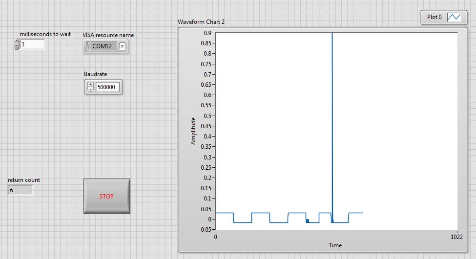
but when I run LabVIEW, it works for a few seconds and Communication all of a sudden abrupt and LabVIEW crash. You can see in picture I capture from my Telechareger below. Why LabVIEW hang?
the image is the front of my VI.
every time it blocks, I have to restart LabVIEW and test again. in the meanwhile I have to said hang occur randomly.
Thank you.
-
Communication Serial Port with PIC
Dear all.
I am interfacing the labVIEW to an eeprom controller PIC, where I need to input data user to store in a location memory EEPROM, according to my condition that I've done programming the pic and it works very well with hyperterminal, at the same time I need to do with a labVIEW using communication serial port VISA , but when I did I receive a warning in 1073676294 that cannot be ignored, but I am not able to write user data to EEPROM by labview but I can do it to hyperterminal, please someone help me on this.
Charron a G
I was interfacing to pictures for a while, and the example that you have to build from was the same that I used. First, move the initialization OF THE outside of the loop. No need to re-initialization of the COMM PORT every 750ms. Inside the code example, there is an expectation of 500ms between WRITING and READING (it is hardcoded for now, you brought it out on the ICON). So time total is 750ms loop over the 500ms wait (more traffic comms), FYI.
You do not use a return of ramasseherbe (13) or a NEWLINE (10) as a dismissal. You use a SO (14). Unless you're on a triggering a 14 ASCII in the PIC, the PIC will never see the "end of the chain of command" to analyze out. I have attached a good routine of init (IMO) I re - use on all my PIC projects, take a look.
I use compilers Mikroelectronica MikroCPRO and displayed a complete interface of the UART (triggers on a CR (13)) on their site LIBSTOCK if you want to take a look at the side of the PHOTO of my work.
http://www.libstock.com/projects/view/250/RS232-interrupt-driven-command-based-interface
Steve
-
Problem with the treatment of the communication data series
I'm working on the communication between LabVIEW and my PIC Microcontroller UART. It works quite well with character Txn & Rxn.But I am facing problems in transmiting and receiving the hexadecimal numbers. through this interface. First of all, is possible to transmit & receive these numbers without ASCII to character conversion & vice versa? and is there an effective technique to deal with our hexagonal. written in the controls of the channel for transmission?
Hi all
Thanks for the reply... I tried the things you all suggested and eventually got in the way to communicate with our hexagonal...
 .. More information can be obtained at:
http://digital.NI.com/public.nsf/allkb/6C24F2F07BC23BB78625722800710865
-
Where can I download and install a driver USB CP2104 UART Bridge Controller and a PL2303 USB driver?
These two drivers are to be connected and program a Bearcat BC75XLT scanner at hand which is held in Windows 7 64 bit HP PC using a USB cable. Help welcomed.
jimTN
Hi Jim,
Thanks for posting your question in the Microsoft Community.
The description of the problem, it seems to want to know where download and install a driver USB CP2104 UART Bridge Controller and a PL2303 USB driver for you to connect and to program a hand held scanner Bearcat BC75XLT to HP computer via a USB cable.
I imagine the inconvenience that you are experiencing. I will try to help you in the matter of fixing.
I suggest you to contact the manufacturer to install the two drivers to connect and to program a hand held Bearcat BC75XLT scanner.
For more information:
Contact Uniden support from the links below:
http://www.Uniden.com/page/contactus
http://www.Uniden.com/page/FAQs
http://www.Uniden.com/downloads/page/downloads/
http://www.Uniden.com/scanners/300-channel-handheld-scanner/Invt/bc75xltg/
I hope that the information above helps you.
In the future if you fall on any question relating to Windows, please do not hesitate to post your request here on Microsoft Community, we will be more than happy to help you.
-
My ipad 3 has stopped communicating with my airport extreme.
My ipad 3 has stopped communicating with my airport extreme. I rebooted, both so that made a network reset on the ipad. He sees the airport but does not connect. It will work on the personal hotspot on my phone.
Hello
If your ipad works with a hot spot that's the Aiirport is the problem
Go to the Apple Web site
support. Apple.com
You may need a software update for airport how old is this do you have another
Router, you can try?
See you soon
Brian
-
Garmin communicator plugin and Safari 10.0
So just upgraded to V10.0 of Safari. Went to connect my Garmin gps and download a new cache of geocaching.com but says need new version of the Garmin Communicator plug-in. downloaded and installed. He acknowledged my GPS but I couldn't send the new cache directly to my gps I could just yesterday. When I check my mac directory I don't see the plugin Garmin communicator as a picture disc. Geocachers out there having the same problem? Arlene
If you control - click on the disk image, you get an open option?
-
I spent hours on web sites looking for advice clean my iMac - they were all dead ends. I send a question to this 'Community' first, but must have done it badly because there was no trace of it. I now have the beach on this computer ball effect. Are there places I can delete cookies etc to help out? Thank you for your help.
horse8905
Don't know what's happening, you do not give a lot of information, but if you have the constant beachballing (spinning wait cursor), which could mean that the hard drive is dying.
Open Console.app in Applications > utilities. Filter, called "String Matching," right, high enter "I/o" without the quotes. What happens when you do this?
Maybe you are looking for
-
Tecra 9000 - Bluetooth drivers
Hello I had a hard drive crash, so I format the hard drive and reinstall windows xp pro.But now in the control panel there is no bluetooth icon.and if I don't get new features, no bluetooth are found.so I download the 'drivers bluetooh battery"of Tos
-
That means to "to quick start" in the BIOS for Satellite
Hello A couple of days, that I noticed everything fiddling with my Bios that you could "fast boot" your computer.What this means, and are there any "side effects" as some programs are not started?
-
When I try to send an email with a photo, I get an error no. 0800ccc0D. Cannot find host "pop 3".
Rest of the message is: Please check that you have entered the server name correctly (where can I get the name of the server of?)Account: pop3Server: pop 3Protocol: SMTPPort: 25Secure (ssl): No.Socket error: 1100Errror No. 00800ccc0D
-
fails to install the bottom of charges
I have 6 updates to download it says I need what Dungeon omitting wiith codes error 0 x 645 and 0x8007064c I tried reseting the computor at an early date, there is no difference.yet down loads are all right also each of 6 say 0 KB, 0 miniutes to down
-
Error CODE 0XC004E003 during the attempt of WINDOWS ACTIVATION
A PROBLEM OCCURRED WHEN WINDOWS TRIED to ACTIVATE. ERROR 0XC004E003 what I would do. need your help. Thank you