Variable color point cloud
Hi all,
Has anyone ever put in place a class derived from point cloud which could have different colors? What about the different width of stripe?
See you soon,.
Cyrille
Hi CD,.
The problem you see is the result of the configuration of the pen. EndCap property is essentially the brush tip style you are using. In my view, that the default is flat, which causes your line look like his zig zag. Instead, use a round tip and you will get a much smoother looking line.
Dim myPen As New Pen (col, 20)

myPen.EndCap = Drawing2D.LineCap.Round

e.Graphics.DrawLine (myPen, pt1, pt2)
Tags: NI Software
Similar Questions
-
Hello
I can't find an example where I can create a custom class plot. I have to be able to line the plot of color based on the value of Y and make it look like a smooth gradient. Ideally, I would like to change the size of the line as well. This would allow me to "draw" the 3 variables using a 2D graph. I started (VB.Net):
Imports NationalInstruments.UI
Public Class clCustomPlot
Inherits from point cloud
Public Sub New()
MyBase.New)
End Sub
Protected / Sub OnBeforeDraw(ByVal sender As Object, ByVal e As NationalInstruments.UI.BeforeDrawXYPlotEventArgs)
End SubEnd Class
But VS tells me that:
Void of MeasStudioGraphLineColour error 'OnBeforeDraw' cannot be declared 'overrides' because it does not replace a sub in a base class.
Thanks for your help,Nicolas
I got it to work! For all those who are interested, here's a VB.Net custom dispersion diagram that will show you how/color along the line of control.
Imports NationalInstruments.UI
Imports System.Drawing
Imports System.Drawing.Drawing2D
Public Class clCustomScatterPlot
Inherits from point cloud
Private dblMin As Double
Private dblMax As Double
Private colMinColour As System.Drawing.Color
Private colMaxColour As System.Drawing.Color
Public Sub New (ByVal MinValue As Double, ByVal MaxValue As Double _)
ByVal MinValueColour As System.Drawing.Color, ByVal MaxValueColour As System.Drawing.Color)
MyBase.New)
"no check is performed for the fact that MinValue<>
dblMin = MinValue
dblMax = MaxValue
colMinColour = MinValueColour
colMaxColour = MaxValueColour
End Sub
Protected override void OnBeforeDraw (ByVal e As BeforeDrawXYPlotEventArgs)
"Clip data, browse the data cut, map and draw."
Dim intrigues as XYPlot = e.Plot
Var clippedXData() As Double = Nothing
Var clippedYData() As Double = Nothing
parcel of land. ClipDataPoints (clippedXData, clippedYData)
For i As Integer = 0 To clippedXData.Length - 2
Protected x 1 Double = clippedXData (i)
Protected x 2 = Double clippedXData (i + 1)
Var y1 As Double = clippedYData (i)
Var y2 As Double = clippedYData (i + 1)
Dim point1 As PointF = plot. MapDataPoint (e.Bounds, x 1, y1)
Dim point2 As PointF = plot. MapDataPoint (e.Bounds, x 2, y2)
Var pen As Pen = New Pen (ValueToColour (y2))
Dim g As Graphics = e.Graphics
g.DrawLines (pen, new PointF() {point1, point2})
Next
e.Cancel = True
End Sub
Private Function ValueToColour(ByVal value As Double) As Color
If value<= dblmin="" then="" return="">
If value > = dblMax then return colMaxColour
Pctg As Double = (value - dblMin) / (dblMax - dblMin)
Dim a, r, g, b As Integer
a = CInt (CInt (colMinColour.A) + pctg * (CInt (colMaxColour.A) - CInt (colMinColour.A)))
r = CInt (CInt (colMinColour.R) + pctg * (CInt (colMaxColour.R) - CInt (colMinColour.R)))
g = CInt (CInt (colMinColour.G) + pctg * (CInt (colMaxColour.G) - CInt (colMinColour.G)))
b = CInt (CInt (colMinColour.B) + pctg * (CInt (colMaxColour.B) - CInt (colMinColour.B)))
r = Math.Max (0, r): r = Math.Min (255, r)
g = Math.Max (0, g): g = Math.Min (255, g)
b = Math.Max (0, b): b = Math.Min (255, b)
Return System.Drawing.Color.FromArgb (a, r, g, b).
Var col As Color = System.Drawing.Color.FromArgb (a, r, g, b).
Return col
End Function
End Class
-
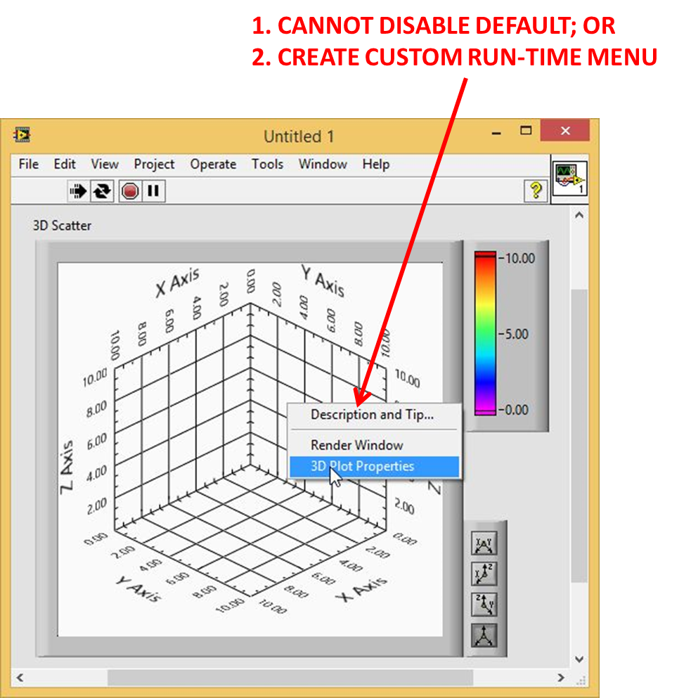
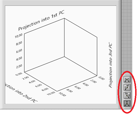
Menu of performance graph 3D point cloud
Menu custom graphic execution 3D point cloud does not (Advanced-> Run-time).
The default menu can also not be disabled. Turn it off does not work (Advanced-> Run - time-> Disable and properties VI-> the appearance of the window-> Custom-> allow default shortcut menus (stop)).
How do you turn off the run menu by default graph 3D point cloud? In addition, how to replace it run with menu custom?
You want to be able to graph 3D right click and select from the menu custom execution. I saw the work around here (http://forums.ni.com/t5/LabVIEW/Solution-3DGraph-right-click-menu/m-p/903569/highlight/true#M407348), but it does not work.
Any ideas?
Hi Battler
You can override the menu right click using the context Menu Activation? and the events of contextual Menu (user) selection.
Don't know what version you use. I've attached an example in LV 8.6.
-
Hello
Anyone know if it is possible to edit a 3d point cloud? I want to be able to move the palette of projection somewhere else and could not find how. Thanks in advance
Gabriel
Hi Gabi11,
in this case, I fear that it is not possible to change anyway. I'm sorry.
Good day!
Jesus
-
Combination line point cloud, or disperse with trend marker
Hi all
I need a line and dispersion of APEX 4.2 combination...
Looks like AnyChart can do it now...
See:
Scatterplot: combination of line and marker Charts & lt; / title & gt; & lt; link href = & quot;... /styles/Sample-Toolbar.CSS & quot;...
And it seems that from the APEX 4.2 yet we cannot do this, if I saw the reference in this forum for a request for improvement for the next version (thank you Hilary)
In the meantime, so I have something...
The need is for a set of guidelines - a box has peaked, for example - to illustrate clearly the points in and out of the limits of quality. In our case, the solid lines are constant for all parcels. Dispersion points, and the series will change according to the data.
In addition, the guide or trend lines are not horizontal or straight - they form a peak, as the roof of a House.
I use trend lines, or I could use thresholds (backstory). So far I do not see how to build a sharp trend line, or a threshold area has peaked. Is it possible > I'm still looking.
Suggestions?
Thank you
Karen
I figured out and just make a simple line - scatterplot.
The trick is, start with the line chart, several series, and then change one or more of the series until the marker using the series Type selection list.
When you start with a Scatter Plot, but this may be more close to what you want in the end, the series Type selection list isn't here.
Reason: Request for a point cloud format is different - you can't dynamically change the type series unless the same query format applies.
-
Impossible to move some color points
I use Safari. I have not had this problem until a couple days ago. All of a sudden I can't move some dots of color on the wheel of color at the top of the screen. But others I can move. For example, when "Similar" is selected as the theme, I can't move the point of the base color or the 3rd color point. but all others can be moved freely. "Monochrome" mode, I can move the point of the base color, but not the other one which is visible by default (color 3, I think). In the modes "Triad", "Complementary", "Paste" and "Custom", the base color and color 3 are locked, but all others are moving freely. In mode "Shades" I can't move anything (the only available point is locked).
(However, in any way I can move each point indirectly by adjusting the sliders below.)Hello
We were able to replicate that if we moved to another shade first base color. Is this the case for you? Let's look at a fix.
Saami -
Point cloud with missing data and 3 sets of data
Hello
I'm doing a scatter diagram that has 3 sets of data in it (i.e. 3 plots on the same graph), except that 2 of my sets of data have a missing value while my third set has all the values. I end up getting 2 lines that are disconnected. I can't just remove the line containing the missing data for the 2 sets of data because since my category axis is time, my data points get shifted and no longer appear at the right time. This is the chart that I have.

Thank you.
Hi Gabrielle,.
If there is a diagram of dispersion, the x axis is a value axis. If you have auto selected for the min and max values on this axis, the scale may change when you remove the data point, 15, 85, but the rest remains in the same position relative to the values on each axis of ordinates. What change will be , however, is the curve on which 15 85 approached a local y maximum.
Scatterplots will always leave a gap in the line/curve of connection where there are a pair of missing data. There are two ways to close the gap.
If the chart is an essentially linear relationship, you can use a calculated value is pair up with the lack of value x. The downside of this is that the representation of this point will be indistinguishable on the map of the other data points, measured.
A better way would be to make two tables, one with the full data set, the other with the partial sets, but with the pair missing completely removed.
Adjust the cards the same size and have the same scales on each axis, then just remove one of the cards except the data points, the curves connecting the data points, the x axis of ordinates and the legend showing the color and the forms used to plot each series.
Give a graphic a transparent filling and place it in front of the other.
Kind regards
Barry
-
Create the field of 3D point cloud
Hello
There is one called VI: create some height to craete Field.vi control of 3D image surface.
"Converts a table of values 2D to a 3D height field and apply field to a 3D object that appears in a 3D scene.
It should be fine for me (this function is interpolated the surface), but I [x, y, z] 3D cloud, where the coordinates are not equidistant points. As I understad the VI can display cloud contact equidistant points. How can I use this tool to display my data?
I tried the Mesh.vi create to display my cloud of points, but I really need the interpolated also surface. Could you give me a few points to guide how and where to do now?
Thanks in advance,
Hi D60!
Sorry for the late reply.
Is your problem still not solved?
If Yes, I looked for examples that use the VI create height field.
I found a code example on the community: https://decibel.ni.com/content/docs/DOC-4765
If your data points are sampled on the same rhythm, you can use the interpolation to achieve the same length.
I guess the simplest is to use the Mathscript node to do this, as in this example: http://zone.ni.com/reference/en-XX/help/371361F-01/lvtextmath/msfunc_interpolate/
Or this VI could be used for the same purpose: http://zone.ni.com/reference/en-XX/help/371361J-01/gmath/interpolate_2d/
Let me know if my suggestions helped. If you have any questions, feel free to post them.
Best regards
-
Change field onBlur, onFocus with variable color - control coding
I have a very simple task that gives me a headache. I think I was looking at it too long.
Here is my code for a field in an AcroForm:
onFocus-
If (event.target.strokeColor == color.red) {}
event.target.strokeColor = color.red;
event.target.fillColor = color.white;
}
else {}
event.target.strokeColor = ["CMYK", 0,0,0,.15];
event.target.fillColor = color.white;
}
onBlur-
If ((event.target.strokeColor == color.red) & & (event.target.value == "")) {}
event.target.strokeColor = color.red;
event.target.fillColor = ["CMYK", 0,0,0,.05];
}
else {}
event.target.strokeColor = color.white;
event.target.fillColor = ["CMYK", 0,0,0,.05];
}
The code works as it should, except for the IF statement it seems to ignore.
There is another code of 'validation' on a submit button that changes all of the fields empty & necessary to a red line.
So what I am once for the fields to set up a "point pleasant" when in normal use, but when someone clicks on submit and an empty field is set to a red line, when the user returns in this area, it remains red and comes back only if they have actually entered something in the field , otherwise it will stay red.
Currently, the field has the "beautiful highlight" onFocus and onBlur, but when the race is going to red, it does not remain red and only uses the properties of "nice highlight" (white and grey).
Who can find the problem? Happy to view the code for the if necessary send button.
By comparing the color objects must be done using the color.equal method, does not the operator ==.
-
Transfer variable color change color to value
Hello.
I have two variables:
var defaultMainHexidec:Number = 0xFFFFFF;
var mainHexidec:Number;
If a value is not assigned to mainHexidec, I attribute the default as follows:
mainHexidec = defaultMainHexidec;
trace ("mainHexidec =" + mainHexidec);
The trace returns the same value as the value returned when the default value.
But if I use mainHexidec as the fill of a rectangle, the color is black, while the default value is white (or any other color). If I set the color using the default variable the filling appears correctly. If I put the number using the number traced in defaultMainHexidec or mainHexidec (she traces the same number) the color is correct.
Someone has an idea, what happens?
Best regards
Chris McLaughlin
nothing does not appear with the code - unless you create the rectangle before loadContent works?
-
Show ToolTips and line graph point cloud where data extracted by SQL
I'm looking to create a scatter chart to display the results of a SQL query. The graphic appears as
I want to have the points to is joined by a line and - bubbles that appear when a single point are selected. My existing custom XML is displayed at the bottom of this post. I tried different formats between the < / tooltip_settings > tags, but nothing appears. Similarly, I tried different line format settings. Interestingly, if the string #DATA # is replaced with a block as...
< data >
< name of series = 'Dirty' type = 'Line' >
< y = '1.172' point x = "1063512000" / >
< y = '1.916' point x = "1095048000" / >
< point y = "5.57" x = "1126584000" / >
< point y = "15.0" x = "1158120000" / >
< point y = "144" x = "1189656000" / >
< / series >
< / data >
... then a line and bubbles appear. It seems that all that is in the #DATA block # is not enough to create a line, and ToolTips. The data is retrieved by a query that returns the 4 columns LINK, TAG, X_VALUE, Y_VALUE
Is there a way in which something can be configured for line and tool tips to appear?
Existing custom XML
<? XML version = "1.0" encoding = "UTF-8"? >
< anychart >
< Parameters >
< local >
< date_time_format >
< format > %u < / size >
< / date_time_format >
< / locale >
< / Parameter >
< graphics >
< graphic plot_type 'Scatter' = >
< data_plot_settings >
< line_series >
< tooltip_settings enabled = "True" >
< / tooltip_settings >
< / line_series >
< / data_plot_settings >
< chart_settings >
< title >
Scatter line < text > < / text >
< /title >
< axes >
< y_axis >
< title >
< text > County < / text >
< /title >
< scale type = "Linear" / >
<>labels
< format > {value %} {numDecimals:0} < / size >
< / Label >
< / y_axis >
< x_axis >
< scale type = 'DateTime' major_interval = '1' minor_interval = '3' major_interval_unit = 'Year' minor_interval_unit = 'Months' minimum_offset = '0' maximum_offset = '0' / >
<>labels
< format > {value %} {dateTimeFormat: % YYYY} < / size >
< / Label >
< title enabled = "true" >
< text > Date < / text >
< /title >
< / x_axis >
< / axis >
< / chart_settings >
#DATA #
< / chart >
< / charts >
< / anychart >
This is because the apex generates the series not as a type of line, but as a type of marker:
... You will need to provide the data yourself, in the format you want, that is to say a series of line type. You can't set it up.
-
How to make a conical point clouds brush?
Hello, I would like to make a path (spiral) and place a brush (a symbol that looks like an ORB) on the spiral and have become smaller as she goes down the path. I made a brush of the ORB and then applied as a brush. I played with the profile of the race, the scatter brush settings and searched the internet/forum. I probably approach it the wrong way because it seems that it is impossible.
All tips/best practices to do this? In this image, I want the ORB to become smaller as it goes along the spiral.
TIA

Chris,
If you want to have the same distance between the orbs (gaps by increasing as decreasing size), you can:
(1) create a mix between a larger and a smaller ORB with the desired number.
(2) select the path and the object > Path > Add Anchor points a sufficient number of times to ensure a constant distance;
(3) select the two and object > blend > change the meaning.
(You can undo 3) and 2) If you did too little anchor points.
-
find the distance between two major axis chart point cloud
Hello
I have a scatter chart. Its the y-axis AutoScale property is set to false. The major and minor axes are by default. Interval is set by default.
When draw the graph divisions displayed on the axis are defined according to the range provided. Sometimes, the interval between the major divisions, that is exactly what is defined in the Interval property and sometimes this isn't the same thing. As mentioned in the help the AutoScale property is set to true, sometimes by himself in order to avoid the congested labels.
What I find is the distance beween two major axes of the value axis, as the interval is not the same as set in the property.
Kindly let me know how to calculate the interval.
Kind regards
Nihad.
yAxis1.AutoSpacingMajorInterval
Replace yAxis1 by what is called your axis y on the scatter graph. If you don't know what it is, right click on the axis are the scatter graph, and then select Edit YAxes. Then a box will appear and you can see how it's called in the members section.
-
Problem with point clouds brush
My brush of dispersion is the last line of Cyan, I would like to get a single line like in the second picture, but what I realize when I put on the race is the separate ground you can see, even if I use the Brush tool
I work on win 7, CC 2015


Then, you must assign a smaller distance in the options. It might be a good idea to randomize the angle as well.
-
points with color on a scatterGraph diffenrent
Hi all
I want to score points with diffenrent color on a scatterGraph. The color of the point must be made based on the values of a combination of the primary color (red, green, blue). Perhabs I should use the 'Color.FromArgb (red, green, blue)' method to change the color. but I used the "scatterPlot.PointColor = Color.FromArgb (red, green, blue)" to change the color of the entire points on the ground. The number of points I have is more than 80,000. You have ideas better?
Respect of
Michael
Hello
You can customize the way points are drawn in the graphic Studio measure controls. See the example in chart that comes with Measurement Studio (... \Graph\CustomStyles\...).
You can customize this way...
1. write your own CustomStyle deriving from the PointStyle class.
2. override the Draw() method.
3 override the IsValueDependent property and return true.Here is the code snippet sample showing the same thing,
Use an instance of these classes of style for scatterGraph.PlotStyle.
Point color is based on the data.
public class MyCustomStyle1: PointStyle
{
Dispersion of the cloud of points;
public MyCustomStyle1 (ScatterPlot myPlot)
{
Point cloud = myPlot;
}Public Overrides Sub Draw (context of the object, PointStyleDrawArgs args)
{
Graphics g is args. Graphics card;
Double x = 0;
Double y = 0;Rectangle rect = new Rectangle ((int) args.) Graphics.ClipBounds.X, (int) args. Graphics.ClipBounds.Y, (int) args. Graphics.ClipBounds.Width, (int) args. Graphics.ClipBounds.Height);
You can get the data points x and y by the reverse mapping.
scatterPlot.InverseMapDataPoint (rect, new PointF ((float) args.)) X, (float) args. Y), x, y);Color c = Color.White; Replace the code here to map the value of your data with a color value.
g.FillRectangle (new SolidBrush (c), new Rectangle (0, 0, 100, 100));
}public override bool IsValueDependent
{
get {return true ;}
}
}Point color is not dependent on the data
public class MyCustomStyle2: PointStyle
{
private Random r = new Random();Public Overrides Sub Draw (context of the object, PointStyleDrawArgs args)
{
Graphics g is args. Graphics card;
Color c = Color.FromArgb (r.Next (% 255), r.Next (% 255), r.Next (% 255));
g.FillRectangle (new SolidBrush (c), new Rectangle (0, 0, 100, 100));
}public override bool IsValueDependent
{
get {return true ;}
}
}I hope this helps.


Maybe you are looking for
-
video integrated in HP Pavilion 23-f450z TouchSmart All-- One desktop PC in
I plan to buy HP Pavilion 23 - f450z TouchSmart all-in-One desktop PC but before buying it, I was wondering if anyone can tell me what model of video card is on this computer. What it says on the Web site is "Integrated graphics - AMD" any informati
-
How do I do that?
-
charges for all lines and lines without return locations
All,I have a table EMPLOYEE (EMPNO, NAME, PLACE).In this table of records do not have places of location/empty now I want to return all the number of lines and the number of lines where location is empty/nullAs if there is total lines = 21 and 3 are
-
Compaq mini 110 password required
OK, so maybe it's in the wrong section. But I desperately need the password of the bios for my Compaq Mini 110. On the third attempt the error code is CNU9355WPQ Please any help will be highly appreciated. I can't try all codes starting by (e9lo *) I
-
Audit vCentre / ESX 4 environment
HelloI inherited a VM environment years I was wondering if there is a KB / white paper on the best elements to the document an audit?Thank you.