Vectorize an image using Labview
Hello world!
So, I work with a 3D cutting machine (Roland MDX - 15) and I'm supposed to design a program that can load images and burn them on a piece of wood using Roland MDX - 15.
What I've done, is to create a program where you can draw a picture using the tools of sketch of Labview and the machine will sculpt.
The machine is capable of carving the image using vectors (she follows lines point by point).
Now, I have to do the same thing, but an image that I have load in Labview. Therefore, I need to vectorize the image so that the machine gets a set of lines to draw. A program that is already it is Dr.Engrave (see youtube if you need to understand what I need).
So, anybody know a 'simple' way to transform an image into a set of vectors?
Thanks in advance!
Valentine
Hello VGans,
I assumed that when you talk of tracing any edge detection method would be allowed to help you get started.
If it is a false assumption, then let me know.
Keeping this in mind:
Already taken a peek at the "IMAQ CannyEdgeDetection' VI?
This could be a good starting point for tracing purposes.
Can you let me know if that's what you're looking for?
Tags: NI Software
Similar Questions
-
waveform, with an average of results using labview to O-scope
Hello fellow engineers! I'm a first-yeargraduatestudent in CHEE at the University of Houston. Basically, I know nothing about labview. I am trying to program an application that looks like this - I collect a waveform of the signal of O-scope. This waveform does not change its characteristic shape. I need to find the wave form average of waveforms of N (100 for example). Thus, the slight changes (or noise) in the feature of form during the period mustbeaveraged out and I need to have a resultant waveform that represents the average waveform over a period. So, basically, I'm collecting the wave several times (for example 100) on a single period. The O-scope that I use now is Tektronix TDS 2024 B. It communicates with the computer via USB. The version of labview is 8.5. For now, I am able to communicate with the computer using our o-scope through labview. I already downloaded the driver of instruments of your Web site. It turns out that the program can give me only the average result I can get directly from o-scope manually. I need to have more say on average (100) using labview. I wrote a program that relies on the instrument driver that is downloaded on your website (for loop part is average, the waveform). The program that I modified and an instrument driver are attached. The program cannot be fully open, if the driver is not put in the right place in the labview (under lib inst.) When I run the program, the average waveform does not appear on the front panal and signal waveform file is not saved correctly. Is there someone can find where I did wrong and it develop for me? Because I barely know Labview, it will be even better if you can add an image or program that you have changed. I'm waiting for your creative ideas.
With the best regards,.
--
Weiye
-
Is it possible to compare two PDFs using labview?
I was wondering if it was possible to use LabVIEW to compare two PDF files (that contain images as well as text) to another. I know that Bluebeam PDF viewer can do, so I was hoping there was a way to do it with LabVIEW.
Read each file as a simple string, and then compare the two strings for equality.
(You can also do a few tests before, for example just to see if the sizes are equal)
-
Manage a webcam using LabView, how?
I have a small webcam (usb) I would use to acquire images with LabView. MAQ does not recognize it and it does not appear on the list of the Non Plug and play devices... any suggestions?
Thank you.
Here is a link to the currently supported IMAQ USB software by NOR.
http://sine.NI.com/DevZone/CDA/EPD/p/ID/5030
Hummer1
-
How can I display the time of the data stored in a file using labview?
How can I display the time of the data stored in a file using labview?
Hi Matt,
I think that we will need a little more information as to how you capture the data, what data you capture, etc.
If you capture a waveform, is to extract the time data waveform which includes the t0 and dt values, so you can understand the time stamp of a specific data point as in the image below.
-
NEITHER CVS using Labview Linux?
Hi, I have a CVS here, as well as 1455 development under labview linux machine. I've used MAX to set up this CVS, but it seems that my labview is not MAX, and I can see on the site it seems to be available for Linux. Could someone point me in the right direction to set up/use my CVS using labview linux (I've got installed 8.5).
You need to write code CVS to turn an image into a table of number using IMAQ ImageToArray.
Then, use the shared variable or TCP/IP to return data to the host VI.
However, there are two things to remember:
1. an image won't be like in real-time, as show on VI target itself.
2. because the Vision Development Module does not support on Linux, all the processing of the image on Linux must develop in yourself.
-
some computers cannot acquire images using the PCI-1410
I have a big problem in the acquisition of the images using the PCI-1410.
It was a standard camera (SONY XC-ES). The test of the device is OK with my computer.
I can not get a correct image via MAX. Also, I try to use the file of the camera for that camera.
But it did not work properly.
I consulted it toward the Korea of NEITHER and they discover THAT PCI-1410 worked properly with different computers.
So, I try to change PC. Most of my computers cannot acquire the image even if the unit is OK of MAX.
However, only a few computer works properly. (Work computers are from SAMSUNG. The other
computers that did not work propely, were assembled in the lab.) (I have tested almost 6 computers for this purpose.)
The problem is that there are at least 3-4 PCI ports for our applications. The work computer (SAMSUN) only has 2 ports PCI.
What should I do to select the right computers? I can't buy dozens of computers to test the PCI-1410.
Why is this kind of problem occurs?
Thanks in advance for your advice. (Email: [email protected])
Hello
We also had a lot of problems in the past with different PCs and the problem came from the motherboard. Since that time, we only use motherboards with intel because we know that labview works very well with them.
It was 2 or 3 years ago, and I thought that the problem has been resolved since then... you know the type of motherboards you use?
-
Hello
I can restore images from raw data using labview? If possible, what kind of data can be used?
For more details, im trying to get a thing called 'line-data' to an acquired image of an ultrasound machine and I want to rebuild this image of these data using labview. I am able to do? However, I also need the above answered the question.If any additional information is needed, just tell me and I'll provide you with everything I can.
Thank you for helping me.
I have IMAQ, IMAQdx, Vision Module installed.
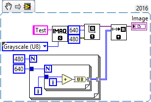
An Image is an array of Pixels, where a Pixel can be one U16 or U8 to grey scale of images or a 32-bit value if he holds the RGB data. It's the first thing you need to consider, what are your Pixels, i.e. to the data type that you use to generate the image.
Now, many groups of the Image have sizes as 640 x 480, or X and Y 'resolution' (number of pixels of adjustment in the X direction and Y). Note that 640 x 480 is a common size for cheap USB video cameras. A minor confusion is that the corresponding table of LabVIEW (for example, of the U8 Pixels) will have the dimensions 480 x 640 - this makes sense if you think that "480 lines, 640 columns in the X direction and the axis Y.
So now you have your table Image, so fill out the Pixels that you need. This will depend, of course, what you are doing. If you perform an operation of "analysis of the line" (which I assume means you get, say, a row of pixels at a time), simply create you your table Scans of line 1 d 2D.
Here's a demo: it is in 2016 LabVIEW, so you will not be able to copy in your block diagram (unless you also 2016), but it is simple enough that you should be able to find the functions of the IMAQ Vision utility pallets (pallets). See if you can "predict the image"...
Bob Schor
-
It is possible to capture and record a sequence of images with a LVDS OR 1422 EZMaker using Measurement & Automation Explorer? Everything is installed correctly and running and I am able to use the "Snap" command to save an image, as well as the 'Grab' command, but it seems that you must stop the dump command before you can save anything, and it only allows you to save the final image. Is there a way to record a sequence that is being caught, or should I use LabVIEW or other additional software to do this?
Kind regards
James S.
Hello James,.
You will need to LabVIEW or another environment development in order to record a sequence of images. If you have LabVIEW and the Acquisition of Vision software, you will be able to capture and save images in an AVI file. There are examples that come with the Acquisition of Vision software that can do this.
I hope this helps.
-
I'm trying to vectorize an image but struggling to get the right settings for the CS6.
Hi all, I'm trying vectorize an image, but im struggling right now. I would like to get the same effect as this: http://fav.me/d4p907m. If someone knows how its done or if I'm close to having the right settings? http://i.imgur.com/5Oka65P.jpg (my attempt is the one of the far-right, the cs6. The one on the left, in Paint.NET, is the desired result. Thank you for reading.
You will need to change this image in Photoshop before tracing. Then vectorize with 6 to 8 colors.
But you'll still need to edit I subsequently. There is no way to get the eyes in this Green using autotrace. It goes the same for lips.
You must also consider the piece manually.
-
How to make a zoom in on part of the image using editing?
Recently returned to the opening. Do not remember how to enlarge the part of the image using editing. If the answer is Loupe tool, please remind me how it works.
What version of Aperture do you use?
To zoom the viewer enter the combination of keys command - + (⌘ +) or press the zoom-viewer:

If you prefer the magnifying glass, launching it from the view menu with "view Magnifier, where also find magnifying glass options to switch to a centered Loupe or show the grid under the microscope.

-
Screenshot of Tektronix MSO4104B using LabVIEW
I am trying to acquire a screenshot of an oscilloscope Tektronix MSO4104B using LabVIEW. I am currently able to collect data from the device and have a waveform displayed on my front of VI. However, for various reasons, our preference is to capture the actual screen shot of the scope.
I have reviewed the reference for programmers for this camera and have done countless searches on Google for an answer, but have not been able to find a solution. It seems that a few people were able to reach on OTHER Tek scopes by sending a hard copy through the port of communication (GPIB, USB, Ethernet, etc.), but according to the reference of programmers for this particular device, it seems that he will send a paper copy of an installed printer, rather than simply as a stream of data to the port which can be read using VISA controls.
The other solution I've seen is to record the screen turned to a flash drive, and then copy the file via the port to the PC. However, none of these solutions seems to be available on this device... it's one of the more advanced scopes makes Tek... I can't believe it's so hard! Help, please!
-
I want to send data using labVIEW to arduino using write visa and the process and to take action using arduino. After that, I want to arduino to send out necessary via a serial port to labVIEW which should be read using visa read and store in a chain. While I am able to write or read both individually, I can't do it consecutively. I used advanced read and write vi for checking my code, but nothing is helping. The wrong bed 'time delay before execution. " Please let me know where I can go wrong. Also is it possible to write code for hx711 using labVIEW
1. you need not "\n" on your orders println(). This command adds an end of line character already in the message.
2. you get the error because you have a loop around your reading. After the first reading (well technically, the second because of you add an extra line end character), there is nothing left in the port. As a result, you will get the timeout.
3. you should really consider using a Structure of the event. This way you just don't write and read when you press the Write button and you can also use the structure of the event to make the loop to stop. I also go up to close the port inside the stop-> value Change event.

-
How to check the CPU usage and paging using LabVIEW
Hi guys,.
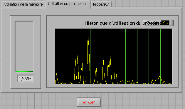
I build an application that is used to check the CPU usage and paging using LabVIEW. How can I do?
any help, suggestions or advice will be greatly appreciated...
Kind regards
Prashant
Hello
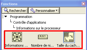
If you plan to build your app for Windows, you can use .NET classes. (System.PerformanceCounter), there is a simple example with LabVIEW:
C:\Program NIUninstaller Instruments\LabVIEW 2010\examples\comm\dotnet\SimpleTaskMonitor.llb
Also, you have several screws that you can use to verify information about the processor.
Kind regards
-
Programmatically insert step of ActiveX/COM using LabVIEW
Hello
I would like to be able to create sequences like the one set using LabVIEW.
This sequence has only 2 steps, a LabVIEW VI call and an adapter of ActiveX/COM call.
I was able to do using an adaptation of the code here: https://decibel.ni.com/content/docs/DOC-36337
However, I am struggling to add the step of the ActiveX/COM.
Any help would be welcome.
Thank you
Of course, there is a way, if you look for it

Since you have an existing 'Step' class object, you can also get a 'Module' object for her. Subsequently, you will need to specify that it is an ActiveX module. If you do not know which - probably you need to get the object 'map' somehow... Our case is simpler, so just cast to the ActiveX module and... to set certain properties like ServerId, ActiveXReferenceExpr and so on.
I've attached an example for you. Interesting thing is the ServerId - I just read this chain of the TS for similar action and reused it here so do not ask me how to get automatically
You will need to complete your 'properties' as 'file' - but I'll gracefully leave this work for you =.
Best regards


Maybe you are looking for
-
Firefox should display files .swf and .flv without Adobe. You can do it can't you?
If the "Media Player Classic" program can read files .swf and .flv, programmers probably Firefox can do for those that did for .pdf files. PLEASE, I BEG YOU!
-
How to remove an obsolete alternative e-mail address, Hotmail
When I click on 'remove' next to the alternative Email address in Hotmail account, a message is sent to the alternate Email address on how to proceed. I can't access this old, obsolete address to go forward.
-
Impossible to uninstall Adobe Reader Error 1402 could not open key. Fatal error during installation
try to unstall adobe because or a 1402.and code reinstall date adobe reader. try to read my email.
-
Pro XP Recycle Bin is corrupted?
Fix it scan reveals this problem without solution. I really didn't not at all understand this problem.
-
What is maximum photo managed by printer Photosmart 8100 card format?
I looked in the manual and nothing is there. I'm trying to avoid having to spread the pictures on 2 or more cards.